Several timers loop data acquisition
Hi all
I am developing a VI for FPGA Deployment. My equipment consists of a chassis/controller for cRIO-9072 with module 1-9211 thermocouple, card SD-1 module, 3-9215 HAVE modules and universal modules 2-9219. I will collect data of two thermocouples on the 9211, 14 channels on 9215 channels and 6 on 9219 modules. This system communicates to the host via ethernet.
I have prepared a vi (see attachment), which used two DMA FIFO for writing data to data acquisition at a different speed. I will be sampling the s and 9211 9219 much more slow (500ms by samples), than other channels (40 ch/kech. / s). Currently, my FPGA vi trying only to taste two different modules. When I run the present on the host vi and try to read the data, I get only extracts of the data at different intervals. If either of her would reveal latency with the connection or the host vi failed to refresh quite quickly? I am relatively new to labview, so any help is appreciated. Thank you.
Gaussy
Hi Guassy,
There are a few things that you need to change:
(1) you must separate your acquisition in the FPGA in two separate loops if they have to operate at different speeds. As it is, probably will run at the slower speed of the two parameters.
(2) you must do the same in your VI in real time, or set up the DMA readings so that they will be read at the same pace. For example, suppose that a single module acquires 1000 hz and the other at 200 hz. If you want to read 100 samples from the first module (so your reading will occur at 1000 hz / 100 samples = 10 hz), you will need to read 20 samples from the slower module, so it is synchronized with the first module.
(3) your timeouts are too short on your DMA readings. Your slow acquisition is 500 us. It will take 50 ms to read 100 samples requested, but the delay is set for 10 ms, so 4 times over 5 playback will return nothing.
(4) you use graphics and no graphics. A chart will only show the current data buffer that was written for her. Refresh rate of the façade is nondeterministic, so that you can't see every update. If you use a chart, the chart will record all data written on it to the indicated depth (default is 1024 elements).
Also remember that you can have three FIFOs DMA between the host and the target FPGA, so use them wisely. It is often easier to perform your purchases on the FPGA at the same pace and send them through the DMA FIFO even in VI in real-time. If you need a few channels to connect at a lower rate, you can always throw the excess samples (there are some decimate wave screws that are perfect for this).
I hope that helps!
Tags: NI Software
Similar Questions
-
choice of the model of design for data acquisition system
Hi all
I have a problem on the selection of the model design / architecture for a data acquisition system.
Here are the details of the desired system:
There are data acquisition hardware and I need to use by looking at the settings on the user interface.
the period of data acquisition, channel list to analyze must be selected on the user interface. In addition, there are many interactions with the user interface. for example if the user selects a channel to add scanlist, I need to activate and make it visible to others on the user interface.
When the user completes the channel selection, then he will press the button to start the data acquisition. Then, I also need to show the values scanned on a graph in real time and save them in a txt file.
I know that I can not use producer consumer model here. because the data acquisition loop should wait for the settings to scan channels. and it works on a given period by the user. If the loop of user interface makes higher then loop (loop data acquisition) of consumption. This means that queue will be bigger, larger. If I use notifier this will be some data loss comes from the user interface.
y at - it an idea about it? is there any model of design suitable for this case?
Thanks in advance
Best regards
Veli BAYAR
Software for embedded systems and hardware engineer
Veli,
I recommend the model producer/consumer with some modifications.
You might need three loops. I can't tell for sure from your brief description.
The loop of the User Interface responds to the user for configuration entries and start/stop of acquisition. The parameters and commands are passed to the Data Acquisition loop via a queue. In this loop is a machine States that slowed, Configuration, Acquisition and stop States (and perhaps others). The data is sent to the processing loop through another line. The processing loop performs any data processing, displays the data from the user, and records to file. A registrant can be used to send the Stop command or stop the loop of the UI for other loops. If the amount of treatment is minimal and the time of writing files are not too long, the functions of processing loop might be able to happen in the case of the UI loop timeout structure of the event. This makes things a little easier, but is not as flexible when changes need to be made.
I'm not sure that there is a type of design for this exact configuration, but it is essentially a combination of the models Design of producer/consumer (data) and producer/consumer (events).
Lynn
-
synchronize two loops for written tdms data acquisitions
Hello
I have two loops of different data acquisition. A slow acquisition of CAN (10 s/s) and an analog acquisition faster (30 samples taken at a frequency of 300 Hz), I need to synchronize these data for tdms writes for later analysis in DIAdem.
My example and the result in the DIAdem channel list is attached.
Thanks in advance!
Magnus
Magnus,
for a professional solution, you do not want to synchronize the devices on a hardware level. Since the material CAN work differently to 'traditional' DAQ devices, there are important things to take care of.
Please look in the viewfinder to LV example for the word "CAN". For example, you can choose the example 'several cards CAN and DAQmx map Wfm Input'.
Norbert
-
Data acquisition reading incorrect when you use a loop
Hello
I wrote a simple VI (00, 01, 10, and 11) output to a circuit connected with 4 resistors. Based on what value the ciruit receives, it passes current through a particular resistance. It is again entered in Labview and traced.
The problem is when I send a particular value (i.e the 00, 01 and 10 and 11) and get that back, it's okay. But when I send and receive the consectively connected via the loop counter, they are incorrect (not synchronized with the number of the loop).
I made sure that circuit works very well. It has something to do with the loop synnchronization, reset, value compensation, etc. can be.
Please Guide...
Change your DAQ assistant that reads to be 1 sample on request.
Right now it is set for continuous samples. And 10 samples at 10 Hz. Then it runs and starts. The next iteration, you send a new digital out, but the wait for 4 seconds. When you read again, you get the next 10 samples that are put into the buffer of data acquisition, but now 40 samples have actually entered the DAQ buffer. In time your DAQ buffer will be finally complete and raise an error. In the meantime, you will continually read data continues to become more tainted by the iteration.
-
Using the SMU-6368 module, I would like to monitor the analog signal on multiple channels and trigger on several channels - relaxation and acquisition channels is all on the same device. Probably going to be sampling at 200 kHz and more. FM LV 2009 2012, with SV toolkit in Windows 7.
If SW trigger is the only way to follow, there example code shows how to manage the block size, etc.. ?
jkessler,
Yes, the example was in 2012. I didn't get what you asked for in your first post because I didn't know you wanted to ANY channel to trigger acquisition of all channels. It is not possible at the hardware level, because you cannot specify four channels as the command source. This will be implemented in the software. I recommend the reading of all four channels and neglecting data until you determine that one of the channels reached your threshold value.
Kind regards
-
You can trigger through communication Modbus TCP/IP PLC data acquisition without using a loop for?
Hello
I am trying to contact a facility through a Modbus TCP/IP communication PLC. I'm new to this method, but the idea is that the installation will send the logical (Boolean) values 1 bit by ethernet to my workstation which read and then will begin data acquisition. Basically, I need a triger to come to my pc. I placed my vi inside a structure case T/F which will run according to the signal, it receives data acquisition. However, for it constantly waiting, I put this in a loop for. The works of vi, but playback signals sometimes lagging behind due to the loop for. If I take the loop out and just run labview permanently, it works perfectly, but I know that the option is only for debugging and should not be used. So my question is, is there a better way to wait for an incoming signal?
Hello!
Please note that the order of execution of the write operations on the shared variable 000002 is not determined.
For example, nothing prevents this order of execution:
(1) value false 000002
(2) set to true 000002
(3) execution of the loop
In what concerns the delay, you might consider placing a waiting vi in the case of 'false', or the loop uses 100% of CPU if I'm not mistaken...
Kind regards
Marco
-
LabVIEW data acquisition Setup Multifunction DAQ
I have doubts as to the acquisition of data in the LabView environment. I used the block diagram (Figure 1) below to review the update of the readings for the execution of a loop.
Block 1 has been used to enable a task (first steps) with 3 channels (al) analog input AI3 and even set up the channel. In this case, the data bus (data-block 4) are construindos by 4 columns of data (provided by task 3 AI3 more).
Block 2 is used to set the sampling rate in this case is 1 Hz (1 sample per channel x 1 rate).
In this case, it worked as I expected (Figure 2). This allows to conclude that the interval between each sample was 1 second. The saw took a second in the iteration.
The second step was to change the amount of data sampled in accordance with Figure 3 channels in block 3.
Now, each channel showed 10 samples, while there are 4 channels configured, we have 40 samples. In this case the iteration totalled 10seconds (point to 1 Hz and 10 samples per channel-figure 4).
The first question is what is the time between each sample obtained by channel?
In this type of configuration (multiple channels), block 3 provides 10 samples in each channel, as well as the sampling is done, IE, the block gets 3 10 samples from a channel and passes to the next channel or gets 1 comp each channel and repeat this process up to 10 samples per channel?
What is the best way to make sure that the interval between each sample is constant?
If anyone knows any text that explains what the function blocks of data acquisition information please.
Thank you
Gabriel
Well, there are several ways to read the signals of multiple signals, and each of them has different behavior. I couldn't see how you get mutiple channels, because in the two codes, you set a channel in your codes. Take a look at this figure:

Here you can see how to set multiple channels using DAQmx, using commas to separate the channels. About the ways different ways that you can read the signals, you can look at the links I sent in my first post to learn more about them.
In a few words, the time between samples from the same channel is T = 1/Fs, corresponding to the sampling frequency Fs. It is not a rule to determine the interval between samples from different channels, because it will depend on how you did your code, and as I sad, there are different ways to do. You can acquire the samples at the same time, or you can configure your code to read a fixed number of points of a channel and then read another fixed number of samples to another channel (https://decibel.ni.com/content/docs/DOC-28279). You can acquire a finite number of points, or you can acquire all the time. Yet once, take a look at the material that I have already sent. It will help you find the best solution to achieve your code according to your application.
Kind regards
Pedro
-
Control and simulation and data acquisition
Hello
I am applying to motor control in Labview. I'm sampling speed from DC engine in real time through an acquisition of data. (my sampling time is 1000 samples per second)
Then wrap speed as input to a Simulation (simulation and design of the order) and inside the loop simulation, I have a PID controller. The PID has the actual speed of the engine for the acquisition of data and the engine reference speed as input.
Reference engine speed comes from the generator of signals (control design and simulation-Simulation) and is a waveform.
My step in the engine size is 1000.
I am running this application real-time and drawing the reference signal and the motor real signals. I run into several problems with regard to the calendar.
1. when I change the size of the step of the simulation loop, the frequency of squares of reference also seems to change. For example. What step size = 1000, duration of pulse = 1 s. What step size = 100, pulse width = 0.1. (My pulse frequency is 1 Hz, Simulation clock - 10 kHz). How step size can affect the pulse width.
2. can you explain the relationship between the DAQ, the Simulation step size loop sampling time, Loop Simulation period.
3. If I want to collect different sets of data using sampling different hours, it's OK to change the sampling DAQ time without changing the size of the step of the simulation.
Would also like to emphasize that the DAQmx calendar under sample clock mode is placed in front of the simulation loop and the output is connected to the loop simulation.
Appreciate any help.
Hello
Maybe some screenshots of your code would help. Furthermore, what you have read your samples together with your DAQ screws?
(1) If you have a waveform, the output is specified as:
For example, if you change the size of the step of the simulation loop, you change the simulation time which are introduced into the signal generator and affecting the waveform that you see if you do not have a size quite small step to characterize the waveform that you generate.
(2) sampling DAQ rate is the speed at which samples are taken on the acquisition of card data itself. The size of the simulation step, help. "Specifies the interval between the time when the ODE Solver evaluates the model and updates the results of the model, in a few seconds." Simulation loop, still using, "Indicates the amount of time that elapses between two subsequent iterations of the loop of control & Simulation.". " "Step size determine the value of t that is introduced to the functions you use in the loop simulation while the loop simulation period controls simply to how fast you change the following t value. The sampling rate of DAQ hardware is a clock of completely separate hardware controlling the analogue-digital on the DAQ card converter so that you can get a deterministic dt between the samples being acquired.
(3) you can change the schedule for the acquisition of data, but you will need to restart each time the changes take effect. If you change the calendar of data acquisition and want your values to correlate with your simulation, you will need to change your size of step as well.
-Zach
-Zach
-
motion control for vertical actuator and data acquisition
Hello
I am a researcher (a branch of civil engineering) geotechnical engineering and I have very little knowledge about the acquisition of control and data motion, so would need a lot of help from the experts OR. I have only knowledge base on these 2 aspects based on my reading of some materials on the Web site of NOR and youtube videos, so I hope that you bare with me
 . Here are my questions:
I am trying to build an actuator which will be used to push a probe (a penetrometer with a load cell to measure the resistance of a soil sample), resembling the concept, photography in the attached file. I need to have these criteria for my system:
(1) actuator, which can push the probe at speeds between 0.01 mm/s - 300 mm/s with precision and move the probe cyclically (upwards and downwards) in the vertical direction
(2) load expected on the probe into the ground range: 0.02kN - 6 kN.
(3) necessary to get the load cell load data and the speed of the probe.4) able to control the actuator to a PC (speed and posotion) and monitor data from transducers and data log time even the transducers.
Guess my beginners is that I will need:
For orders:
(1) software - LabVIEW and NOR-motion assistant(2) controller - NI PCI-7342
(3) driver/amplifier - analogue servo AKD Drive
(4) motor - motor brushless servo AKM
For the acquisition:
(1) software - based LabVIEW development systems(2) amplifiers or other device - no idea what type on the conditioning of signals
(3) data acquisition device - no idea what type
Since I'm a beginner, is - that someone might recommend components (hardware and software) for the control and data acquisition. I'm on a tight budget, so I thankful if someone could help me to recommend components good enough to build my system.
Thanks for your help.
At these rates, you will need to run the sensor for the cDAQ. You can configure the analog output on the Tritex nationally on the position. There is an adjustable filter that you can set in order to get a clean enough to 300 Hz signal. When you learn about the Tritex, make sure that let you them know what comms and e/s that you want to use. If I remember, not all options have worked together. The analog output may need to be my, but you can put a resistance through the acquisition of input data to get the voltage instead. I don't remember all the details. You should really not too much on the Tritex/LabVIEW side. You will send your movement parameters (beginning of end of race, speed, position, accel, cut), and if you cycle (I believe you) or simply running in a loop. You could also just be able to use the functions of jog. When you get close to knowing exaclty what you need, PM me and I'm sure we can work something out with the drivers. You need only the basics. In fact, you could probably do this all your movements via digital and analog i/o.
-
data acquisition won't taste at the specified rate
Material: C - DAQ 9178, AI 9239, inside a servo and an encoder potentiometer module
Setup: I use the 9239 to measure the angular position of my servo and encoder of trees by streaming came pressure pot of the servo and my encoder. I put the sampling frequency on the DAQmx - Schedule VI to 100 Hz.
Problem: I don't think that my DAQ is sampling data at 100 Hz because my VI registers more than 10 000 data points for a 10 second test. In addition, every time I have save my data in a text file, the vector of time my test data resets after a number of iterations.
To debug, I tried the following configuration:
I've defined the sampling frequency of 100 Hz (or is that s/s?), the samples per channel (size of buffer for continuous mode) at 2000 samples, number of samples per channel up to 10 and loop milliseconds timer on my VI at 10 m accordingly, data acquisition would send 100 samples per second (or 1 sample every 10 ms) on my PC buffer (which could store 20 X that amount). Then LabVIEW would read up to 10 samples per loop iteration (which is itself ~ 100 Hz) and work with these 10 samples inside the loop. However, since the loop is operating close to the sampling frequency of data acquisition, then LV should only work with 1 sample each iteration of the loop (100 Hz / 100 Hz)-not the 10-sample-max that I specified.
However, I stumbled on "error-200279: the application is not able to cope with the acquisition of material" when I ran the program. Why?
My code and materials should be easily able to cope with data acquisition - at least the way I put it in place
This whole situation wondered my fundamental understanding of data acquisition timing, so I would really appreciate an explanation of exactly how to deliver DAQmx uses data synchronization, why my DAQ sample at 100 Hz, and how can I fix the calendar specified by the user.
Thank you!
aeroAggie wrote:
The C - DAQ 9178 there some minimum sampling rate I will not meet?
It's actually the 9239 that limit your sampling rate. Read the data sheeton page 5 there's available data rates. In short, your data rate allowed is 50kS/s / n, where is goes from 1 to 31. 50 k/31 gives you 1.6kS / s. So, it's the minimum sampling frequency that can be used.
-
Digital relay of data acquisition
Hello
I quickly ask you questions. Can I connect several relay digital for single block scb - 68 (data acquisition is: 6321 PCI)?
With Labview, I want to enable or disable each of these relays. Is this technically possible? because never, I have connected several sensors to scb - 68.
Each relay acts as a binary switch to a motor brush continuous (3-12 v and RPM motor voltage: 11.5 krm with weight)< 80="" grams).="" the="" dc="" motors="" will="" receive="" power="" from="" external="" dc="" power="" supply="" unit.="" so="" the="" power="" for="" the="" relays="" (i="" am="" thinking)="" must="" be="" from="" daq.="" but="" i="" know="" daq="" can="" supply="" only="" very="" very="" less="" current.="" i="" am="" trying="" to="" source="" out="" if="" i="" can="" find="" relays="" that="" run="" with="" very="" current="" (which="" could="" be="" supplied="" by="" the="" daq="" itself)="" can="" you="" suggest="" me="" if="" this="" is="" possible?="" and="" also="" any="" information="" or="" source="" for="" the="" required="" digital="" relays="" would="" be="" lot="">
Thank you
MSC
-
DSA maxing out CPU data acquisition
I'm developing an application on a PXI-8196 (Windows XP) controller that uses a card PXI - 4472 DSA to read a single microphone and a FFT signal analysis. I need solve the two frequencies of 36kHz (and), so I've planned for sampling 96 kech. / s. I wrote a simple loop of data acquisition, configuring NI44xx DAQ/read screws using read the string unique at this rate, but when I run it, it immediately pegs my CPU 100% usage. So far, I did have problems with missing samples or the system crashes, but I am a little concerned that only data acquisition uses all my CPU time. Y at - it tricks that I can implement to reduce the CPU load?
I tried to vary the parameter samples per channel - with sizes ranging from 1000 to 48000 samples - buffer but I do not seem likely to reduce the CPU usage. Changing the sampling frequency affects the CPU usage (up to about 40% to 48 ksps / s; ~ 75% 72 ksps / s), though. According to this KB: http://digital.ni.com/public.nsf/allkb/D9DDF9FA02D1C18A86256EBC0016C93D
"A controller Embedded PXI-8176 can compute all the time of the spectra of FFT power on 8 channels for PXI-4472 clocked at 102.4 ksps / s »
so I think with my 8196 I should have no problem at all to read only one channel 96 kech. / s.
Anyone have any suggestions to reduce my CPU Overload? Thank you!
Here is a link to some good information on how to OR-DAQmx 7.4 and later behaves with respect to the use of the processor: Default CPU use with NOR-DAQmx Version 7.4
-
LabVIEW statechart module of data acquisition error external trigger
I have a 2 loop vi is the acquisition of data of a data acquisition instrument loop and the second is a loop to run my statechart of. I would like to respond to an error in device of acquisition data if it occurs in transition out of my current state in my diagram States-transitions and enable management of custom unique business mistakes. My States-transitions diagram is synchronous and send it external trigger.vi funciton will not work with it. How to achieve this? In addition, there is some confusion about this literature in http://zone.ni.com/reference/en-XX/help/372103F-01/lvscconcepts/sc_c_callervi/ at the bottom of the page it saidNote sending triggers for synchronous charts is optional. If you do send triggers, LabVIEW sends the NULL trigger for transitions. If you send a synchronous statechart triggers, you can send these triggers to the caller VI. »
Is it possible to do this and if so how with the synchronous statechart?
Thank you, it should work for me
-
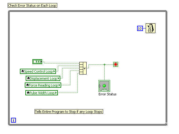
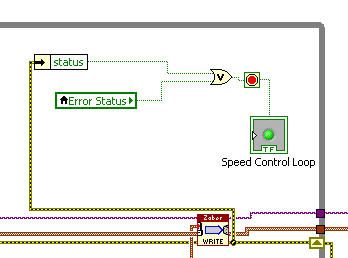
Stop several parallel loops - error & stop button status
I have several ongoing loops run in parallel and want to arrest all a loop based on the question whether one of the two conditions are met:
- One of the loops has an error
- You press a stop button
Right now I do this using a master loop that checks to see if any of the loops have a mistake or if you press the stop button.
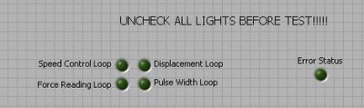
The problem I have is that I do the references between the loops using indicators of State T/F. These lights if it is the judgment of loops. This means that, at the end of a test, all the lights are on, and before the program is run again each light must be unchecked. It is not easy to use and my program grows I don't want to have to uncheck 20 bulbs before each test.
Is there a way to make the lights reset at the beginning of each test, or is there a better way to refer to the status of each loop?
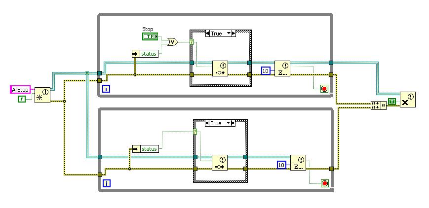
An alternative is to use a notification utility.
Implement a notifier with a Boolean data type.
The stop of two loops of wire to the output of a waiting for Notification (remember to set a time-out).
If an error occurs, or you press stop then send a notification.
By clicking on Stop stop the two loops. Or a mistake in a loop will stop both.
It's not more complicated I think a FG.
-
How to increase the speed of data acquisition?
Hey, currently I using 6210 OR of data acquisition and control switch. I used labview to periodically check the 7 switches and read data from 7 channels in the meantime (1 sample on request). I ran 70 loops for 10 groups of data, the cost of the time looked like 2.2 seconds.
I would like to end a 700 loops in 2 seconds, is it possible to improve?
Thank you
PEM
Look at the Terminal stop of the DAQ Assistant Express VI. You are starting and stopping of the task for the acquisition of data on each iteration of the loop.
Starting from the help file:
Stop
Specifies to stop the task and release device resources when this Express VI ends execution. For ongoing tasks, this entry is FALSE by default, which means that the task is running until the application terminates. To stop the task, you can use the device again in the same application, wire control wire you the Conditional stop this entry to the same terminal of the while loop. For single-point and finished tasks, this entry is TRUE by default, which means work stoppages after all samples are acquired. To optimize the performance of single point when using this Express VI into a loop, wire control wire you the Conditional stop this entry to the same terminal of the while loop.
Also from the help file:
Continuous single point of entry or exit, the of VI Express DAQ Assistant cannot allow optimal operation. See Acq & chart voltage-Single Point optimization VI in examples\DAQmx\Analog In\Measure Voltage.llb for an example of techniques to create more powerful applications, single point of I/O.

Maybe you are looking for
-
How can I better Thunderbird backup on a separate hard drive?
Is there a procedure for backup provided with Thunderbird? I want to backup on a self-supporting USB hard driveWindows 7 Home Premium.
-
X 360-13-4109no spectrum: headphone static spectrum X 360
Hello I just got my new laptop X 360-13-4109no of spectrum. When I use my headset, there is an annoying Static/hiss sound coming out of them all the time, if I'm listening to something. Portable speakers are fine. Also, if I cut her completely, the s
-
H8-1114: h8-1114 bad upgrade to Nvidia 740
Hello I was wondering what I'm doing wrong, or if the card is even compatible with the computer...
-
Executive differential Robotics
Hello I am an autonomous robot using LabView programming and I'm having a little trouble with the vi «Get the speed of frame of steering wheels» I narrowed down it to this simple test, which makes a differential direction image, pass a few tests of w
-
F8 key will not open safe mode
1. the F8 key does not (safe mode) when the computer is restarted. 2. the Microsoft sound does not play at the start and stop of all other sounds functions work perfectly. SYSTEM o Windows XP (home edition) o IE 8 o MS-DOS [version 5.1.2600] o Phoeni