SignalExpress frequency control?
I have a PXI-6713, and I try to use SignalExpress to generate and get out an analog waveform with frequency controlled by the user. I think it's a simple task; I want just one button on my front panel that will allow me to select the frequency of the output wave.
I have a block 'create the form to analog wave' and a block "DAQmx generate the waveform", so I am able to output a fixed waveform. It's that I get, if. It doesn't seem to be an option to add the frequency command directly to the waveform to create step. I also tried to use a block "making the scale and conversion" to treat the waveform after creation, but it doesn't seem to be a direct way to change the frequency.
Am I missing something obvious? Asking too much SignalExpress? I do this in a regular VI instead?
Hello VTChris,
Thanks for posting on the forums! You're not too ask for SignalExpress, it's just that your application requires a feature of SignalExpress which is not commonly used. First of all, you have at least SignalExpress 3.0 is installed? With the release of SignalExpress 3.0, we added the functionality of the operator Interface.
LabView SignalExpress Help: Operator Interface
Operator interface select view"in the menu bar. The Toolbox with available controls should appear in the upper left corner. Place a button control to the bottom and click on the arrow icon to configure the properties of the control. You want to change the related settings for link control for the frequency step setting create an analog Signal.
Be sure to enable the operator Mode when you have finished configuring the button control. Let me know if you encounter any problems with this.
Tags: NI Products
Similar Questions
-
Frequency control of NOR-9476 on the cDAQ-9188
I am using a cDAQ-9188 with a NI 9476 module, and I would like to control the frequency of the digital signals that the module was released. I tried to use the example of Pulse Train digital continuous with control of the frequency, but impossible to select the 9476 since there is no internal counter, and when I change the 'Digital output' task, the frequency control disappears. Is it possible to use the internal counter of frame to control the output frequency of the 9476? I need to get out a range of 0 to 1 kHz.
Most of my program would output a digital signal of a certain frequency every second in real time from a given table. For example, if I have an array of [10, 20, 15, 100,...], it generates a model of up/down of 10 cycles per second for a second, followed by 20 cycles (with a shorter period) for a second, then 15 cycles per second for a second, and 100 cycles per second for a second.
I tried to use avoiding to do, but it was very slow, with a delay of 63 ms between each cycle, when I wanted a 1 ms delay.
CDAQ-9188 has 4 counters built in, but you cannot access it by using the NI 9476-, but the NI 9401 module can access the built-in meters.
The good news is that you can always generate your pulse train, using counters, it generate on the PFI lines on the chassis itself and not through your module. If you need to generate more than a pulse train, or use all four counters, you will need the module NOR-9401/9402.
In order to get the speed, you will need to use the capabilities of hardware counters timing.
I hope this helps!
For more information:
-
Cisco RV320: Frequency on a subnet control degrades the bandwidth on a different subnet
My company has two subnets by using VIRTUAL networking, a default (192.68.0.x) and a guest a (192.68.2.x). I added the frequency control on the subnet of comments, as shown in the attached screenshot (currently disabled rules). When these rules are enabled, by default subnet bandwidth is severely degraded. As soon as I disable the rules of speed control, bandwidth returns to normal. I repeated this test again and again with the same results.
Is there a known performance issue or some other bug with frequency control?
I have the same problem, did you find a solution for your message?
Kind regards.
-
The amplitude of the frequency. Bode CD. State space
Hi all
Gently, I have a simple model that gives me a Bode phase and magnitude, using the block 'CD Bode'. AFAIK, this block takes the representation of the State space and assesses the frequency and scale of the system.
Can I change the value of the Phase or amplitude Bode? by means change the input signal that bode uses to evaluate the response of the State space?
Note: The entry, I want to say here is the value of the sinusoidal signal that Bode uses to give the phase and the amplitude of the State space.
Thank you
The works of Bode CD functions as a "sweep" of all frequencies and who you are. The algorithm is not a frequency controlled, he comes back the entire spectrum. You can't just get a specific frequency. However, if you use the fuction 'Assess frequency of CD', you can provide the model and frequency, and this will give you the specific Mag/Phase for this frequency. This example shows how to do this in LabVIEW:
C:\Program Files (x 86) \National Instruments\LabVIEW 2014\examples\Control and Simulation\Control Design\Time Analysis\CDEx Lin Simulation and stable State.vi
Now, if you want to 'form' your frequency, so you can create another model, connect with each other and try to change the output frequency. This example shows how to do this:
C:\Program Files (x 86) \National Instruments\LabVIEW 2014\examples\Control and Simulation\Control Design\Frequency Analysis\CDEx frequency analysis
If you just want to "simulate" the response of the signal to a specific sine wave, then you will need to you another function in the time domain palette called "linear Simulation CD. With this, you can generate a specific sine wave and you can see his behavior in the time domain. Here is an example:
C:\Program Files (x 86) \National Instruments\LabVIEW 2014\examples\Control and Simulation\Control Design\Time Analysis\CDEx sine wave with Mathscript.vi
Hope this helps,
-
If I replace the control with another why DAQmx create channel once complain a false claim?
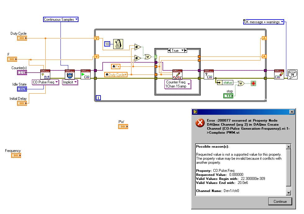
I tried to replace the frequency by another control in the example found here complete PWM:
http://www.NI.com/white-paper/2991/en
However, I get the following error message:

Possible reasons:
Requested value is not supported for this property value. The value of the property may be invalid because it is in conflict with another property.
Property: CO. Pulse.Freq
Required value: 0.000000
Valid values begin with: 22.300000e - 309
Valid values ending with: 20.0e6Channel name: Dev1/ctr0
Task name: _unnamedTask<10>
My wiring diagram looks like this:
If I cancel my change (i.e. I have remove the frequency control knob and turn it over to the control of the example, it works perfectly.) I get the waveform is displayed in the oscilloscope.
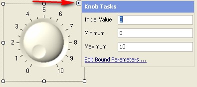
My goal is to simply use a frequency and duty cycle control knob. How can I achieve this?
There are two things to do.
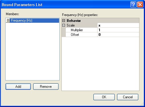
What I think you did now changes the scale of the handle.
You will also need to change the values that are allowed to enter. You will do on the data entry tab in the dialog button properti.
Uncheck the 'use default', the Minimum value limits and Maximum identical to your balance.
Value "Response to value out of range" Coerce to both Minimum and Maximum.
I hope this helps.
Let me know if you have more problems. -
Get lost with the controls on the panels
Hi all,
With the help of Lavwindows 2010
I have a little difficulty with my UIR. I inherited a project with several panels, 2 have about 340 controls on each of them, I'm looking at (for example) a certain (RATE) control properties. I use the tree Panel to get the table I want and the FREQUENCY control. I double click on the name of the control RATE. In the details (under the tree Panel) section, it shows the name of the constant is MLED_MAX12_2 and its status led (its really a digital slide).
Is it just that CVI has trouble with panels containing a large amount of controls?
Is there another way for me to access this control? (right click on RATE and by selecting OBJECT UI FIND gives me the properties of the control MLED_MAX12_2.
Is there a limit to the number of controls on a Panel? of the project? File of the UIR?
Thank you
Pete Hedlund
I couldn't reproduce it in 2010 SP1, so I tried in 2010, and I could reproduce the bug. This problem has been fixed in 2010 SP1.
http://zone.NI.com/DevZone/CDA/tut/p/ID/12323#290057_by_Category
The solution is to change the control in the edit control dialog box that appears when you click on
, when a control has focus in the editor the user interface with the editing tool selected (as opposed to the tool of exploitation). Or you can double-click the control to display the edit control dialog box. -
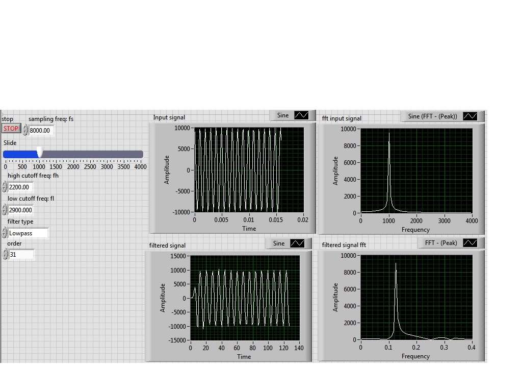
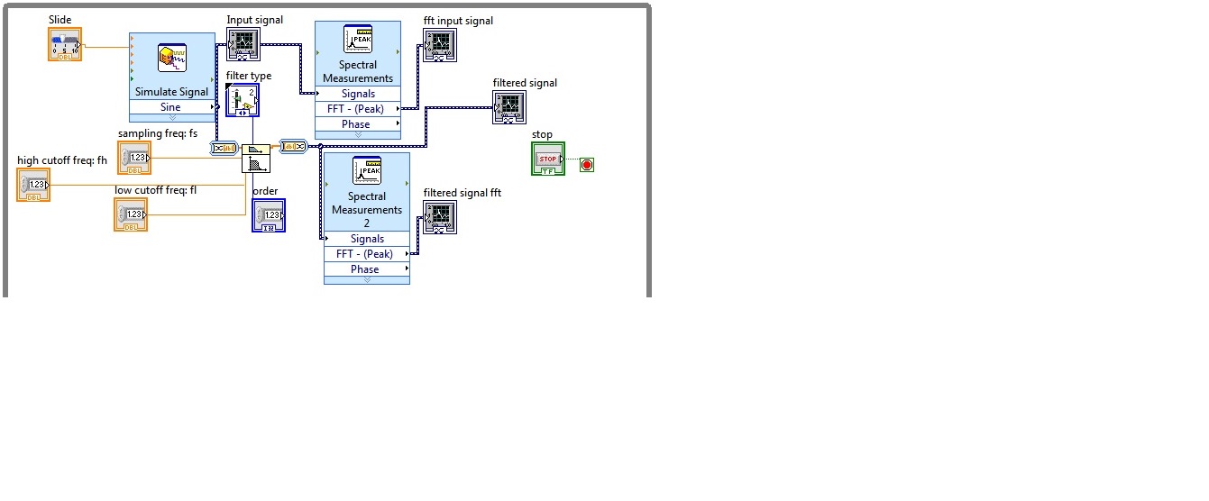
I'm simulating a sine wave at approximately 1000 Hz (I'm variable according to the frequency with a slider), I would like to pass this signal by a lowpass filter (butterworth) with a high frequency of 2200 Hz cuttoff and a low pass to 2900 Hz frequency. However, the output after the filter frequency seems to be lower in the order of a thousand. the output frequency is about 0.1 Hz.
Y at - it someone who can guide me please to solve this problem, I tried different filters and I'm still having this problem, it would be incorrect sampling?
I enclose the block diagram and the front panel
Because you use express screws and the type of dynamic data...
You convert the signal of DDT (which contains the clock information) in a table DBL to perform filtering. Take it a DBL array (which contains no data of timing) and converted it into a DDT (which now contains no data timing). That's why when you try to view and analyze it you have lost all the data timing (frequency).
If you were to exit table DBL of your filter and build a wave form and provide the dt to the waveform of the sampling frequency control, then it will work.
Better yet, ditch the DDT and use waveforms from the beginning

-
How to make a value decrease of time, at intervals of one second
Hello, I am working with an Agilent N5181A to send a command from my code. I've set up the frequency, and now I want to be able to change the value of the amplitude. Right now I have a constant set to-30 and I want to replace it so that it passes from-30 to-80-10 intervals every second.
For example:
-30
-40
-50
etc.
so that in the end, I reached-80, I have attached a screenshot to understand, thank you.
The frequency setting, it's what you pass to the value of frequency control. How often you update the voltage depends on the waiting period. You said you wanted 1 second intervals. That's why I used 1000 msec in the example. Of course you should not put all the code in the loop. Just as the tension and everything what you need (i.e. a measure).
The stop is a control. If you do not know how to create a control on the front panel, you might want to go back and very basic LabVIEW tutorials and review them.
The timeout value is what you want. You said that you wanted to have the values decrease--30 to 80. If this is what you want, use a value of-80 in the control. If you want to stop at-90, enter.
-
Features VI DAQmx differently in LabVIEW that it does in TestStand
I particularly have a VI that generates a square wave signal to control the movement of a motor. When I run the VI in LabVIEW, after a certain time, it stops (a timer is also included in VI). When this same VI is executed as an Action (or boundary Test or pass/fail Test) in TestStand, the continuous PWM signal generating indefinitely after the VI terminated and (if necessary) results were returned to TestStand. If I followed this VI with an another VI which generates a square wave and a 0% duty cycle, the motor stops, as expected. However, I cannot rehabilitate the TestStand sequence without resetting the cDAQ chassis - and even in this case, every other time only. LabVIEW reports an error-200474 (expired timeout) and TestStand reports an error-200088 (task invalid or non-existent) on other tracks.
My questions are: why? and what can I do about it?
Hey Nessalc,
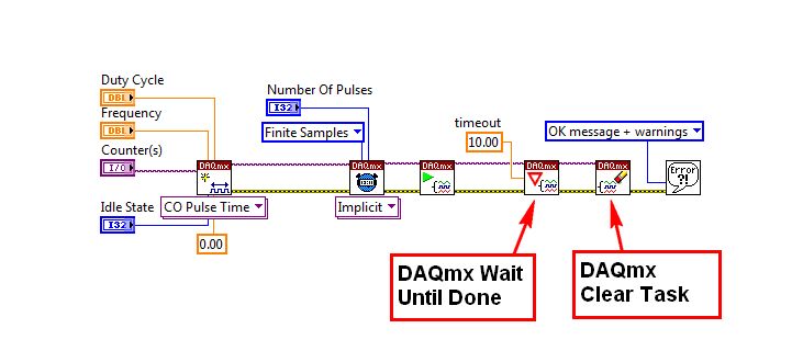
After watching your program, I think I understand why you don't see a signal on your oscilloscope. The test1 VI opens a reference to your task of meter output configures synchronization and then starts the generation time and again and more, without ever giving the working time to generate impulses form. Generally speaking, you would do this with a DAQmx's task made a Subvi wait until done (according to if it is a continuous or finite pulse train).
If you attempt to run a train of pulses for a period of time, see the example called Gen dig Pulse Train - Finite.vi, which can be found in the Finder for example of NOR (material input and output"DAQmx" Generating Digital pulses). Based on the value of the number of pulses and frequency controls, you can set up your device for a pulse train of output for a certain period of time.
I also noticed that you are not clearing your task at the end of the program. It is necessary to free up your resources before attempting to create another task for this resource.
The following image is a screenshot of the example program block diagram (Gen dig Pulse Train - Finite.vi). I have marked the key subVIs that I found missing in your application.
I hope this helps. Let me know if you have questions related to this issue.
-
Several screw-> a Simulink model
Hi all is there,
I am using LabVIEW as a UI for a model Simulink.
According to the user's guide of LabVIEW Simulation Interface Toolkit-> 'using the Simulation Interface Toolkit, you can connect several screws.
created on the host computer to the same Simulink model.
And that's what I'm trying to do. I have a Simulink model test3.mdl and I have generated two screws: inputs.vi and display.vi.
I have traced the commands and views of the two screws for the relevant parameters inside the Simulink model using the SIT connection manager, but trying to run both live and link them to the Simulink model to change the settings and display the results that I get a conflict, alone of the screw can be connected to the model at the same time Simulink.
Does anyone know what are the steps to connect the two screws to the same Simulink model? SIT documentation claims that it can be done, but unfortunately, it does not explain how it can be done. The only examples are used to connect a vi to the model.
Thanks in advance
Jose
Hi James,
In the end, I solved my problem with the second option, I told you before: using static variables to pass data between the two screws.
But it was a little difficult to modify the values of the controls of the façade for the SIT to recognize the change in the value.
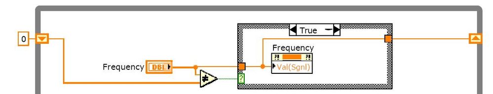
I managed to achieve this by using the following structure for each of the controls of the fron inside the VI Panel where the SIT is running:
In this case to write the value to the control called "Frequency", I have a variable shared 'f' that is written in the other VI where all data entries will be implemented. Then in the "Frequency" control properties, I bound the control to this variable shared 'f' And the using the structure of the image I managed to do the SIT react against changes in the 'Frequency' control and apply the new value to the Simulink Simulation.
The truth is that I still do not understand why the SIT does not recognize the change in the control without using all this stuff, but it's working now.
So could you clarify my doubts about this issue and the problem with the two panels with the SIT fron, that would be great.
Thank you best regards &,.
Jose
-
Hello
I have a problem of small labview.
I want to generate a sinusoidal pulse with labview and send it to a pc oscilloscope using my sound card.
I did first VI creates a sine wave and sends it to the pc oscilloscope. Works perfectly.
But now I want to create a sine wave with a single period (second VI). Problem is while the VI blocks if I want a high frequency (I need 10 kHz)
So the VI operates on frequencies low but gives this error with a higher frequency:
"the audio driver or the card does not support the desired operation."
Can someone give a solution for my second VI (creation of sinus with a period on 10 kHz). ?
Thanks in advance!
Jelle
Hello Benje,
The problem / the difference you see is indeed in coding and also in the sound card.
In the example of 'work' you use the VI of Signal to simulate with the following parameters:
-44100 samples per second (sampling frequency)
-Number of samples 10000 (samples per cycle of generation)
In the non-functional example, you specify:
- sampling rate = 1000 * 'Value of frequency control'. This info of sampling should be fixed (for example) to 441000 Hz.
-Number of samples 1000 (samples per cycle of generation)
As a sidenote:
Is there a reason why you used different functions to generate similar signals in the VI 2?
-
How can I fix my monitor exploded. It says on the display of frequency control PC settings. But the monitor won't stay long enough. ??
Monitors will support only some resolutions and refresh rates. If you set a refresh rate or resolution that your monitor does not support, it could behave as you describe.
Try to restart in Mode safe mode (press F8 repeatedly while booting). Safe mode starts with a monitor resolution that is not pretty, but any monitor should support. Once it starts, right-click on an empty area of the desktop and select "Properties". In the Properties window, change the monitor resolution to something different than the current setup (it is to look good here). If the screen is blank, wait 20 seconds and must return to display and you can select another adjustment. Once you change to any other setting that works, then try to reboot in normal mode and I hope you'll get a screen. Repeat the above procedure to change the resolution to a more convenient setting. If all goes well, which will solve your problem.
HTH,
JW -
Inverter or without drive on Aspire V5-571p-6407
I've been tyring to find a for the v5-571p-6407 frequency control, but were not able to sparepartswarehouse.com or laptopking.com, which makes me wonder if there is a frequency on this model control or if I need to replace the LCD everything? Does anyone know if this model has a frequency inverter? Any help would be appreciated.
Hello
You will need to replace the entire LCD panel because the inverter is fixed on it. Not sold separately.
-
Need a how to: second RV042 DHCP
All, Hy
I have a CISCO RV042 networked with 2 subnets 192.168.1.x and 192.168.2.x and I want several DHCP on both subnets. How can I do?
If I use a second router to the second subnet (192.168.2.x) to use DHCP. Bandwidth management will not work? I need port VLAN?
The network is like this:
The RV042 is the main router through it we internet access, she also suplies DHCP 192.168.1.x, I activated several 192.168.2.x subnet.
The reason I want 2 subnets is beacause I have 2 access points for wireless clients and I want to use the frequency control over WAN with RV042 bandwidth management give too many wired customers more bandwidth than wireless clients.
I know that RV042 does not multiple dhcp as RV180, but I need dual WAN.
Thank you
Wrong forum, post in the "Small Business routers". You can move your ad with the Actions Panel on the right. -
Dual Wan router inaccessible RV042G after the configuration management of bandwidth
Hello
I bought a router of RV042G a few days ago to manage 2 lines adsl at my home. Everything works fine except for one thing: I can't configure bandwidth management. When I go into the menu "Bandwidth management", "Type of bandwidth management" then I choose the frequency control or priority and I have a had a few rules to prioritize the http protocol, for example, then I click the button Save. After a few seconds of internet use I loss the router and internet connectivity and 192.168.1.1 became inaccessible Ping. I had to unplung the power cord to restart the router, the same problem persists until I have remove all the rules! A few times I even had to do a factory reset because my adsl modem is inaccessible behind the router (impossible to do a ping to the gateway).
What can I do? There is a known issue on this router and firmware? I have:
Serial number: NKS16220141 Firmware version: v4.2.1.02 (January 18, 2012 14:10:55) VID PID: RV042G V01 The firmware MD5 checksum: a9817f2dbdcbd6a5c109eaa21b1c3545 LAN Working mode: Entry door Thanks for your help.
Could Pascal you please make a backup configuration file.
Then I would you at the factory to reset the router then once he comes back to the top, login, make your internet work and try the management of bandwidth again without any other configuration. See if it has the same problem.
If not then this would imply some there is a configuration in conflict with the previous establishment or a software defect that has been corrected through the reset.
-Tom
Please mark replied messages useful

Maybe you are looking for
-
A double issue of splash screen
A new Macbook Air configuration, after an attempt abandoned to transfer data from the old to the new mac, I have now two start "screens". It happened because I was prompted to choose a different user account name (probably because there's already the
-
How to restore my Recycle Bin on my iPad?
My recycle bin has disappeared on my iPad. When I try to send something in the trash, I get a message saying: it cannot be moved. How to bring back my trash
-
HelloI have a problem. I need a function that represents a text in a certain angle. I simply create a card application, but now I have a big problem to make labels. Would be nice if someone could help me. I use Version 4.5 of BlackBerry and I create
-
Focus the search field then field simultaneously
Hi all I am currently implementing a screen similar to the contacts application. The title bar contains a search field and main screen contains a list field. The field of research and the field of the list are discussion, so when the user clicks on a
-
BlackBerry Smartphones phone hangs when connected via USB
Hi I have a Pearl 8120. There is a problem where the phone will break if I connect it to some PC via USB. When I say that it blocks the screen turns off and the red light stays on. To recover from this point, I have to unplug and reinsert the battery