Simulate a waveform
I don't know how to simulate a sine wave, so how to simulate a current wave, can anyone show me?
Tags: NI Software
Similar Questions
-
Has anyone ever used a Hall sensor to measure the speed of the engine and crank angle? I'm trying to understand how to measure the lunatics of angle of a single cylinder engine using any data acquisition system. I just need to know what settings or VI is used to translate the output of a Hall effect sensor data into freaks of angle in degrees. I have a 35 teeth wheel, attached to the motor shaft and the installed sensor just in front of it, so I'm 35pulses / revolution. I guess my question is how to manipulate the impulses that I enter freaks of angle in degrees? Do I go about it as an incremental encoder or can I use your extraction, etc. Any suggestion will be appreciated. Thank you.
Thank you Rob, but I already found this earlier; I guess I would have deleted the post. I have a speed of 36 teeth removed a tooth to serve as an index (by aligning it with the TDC marker on my wheel engine) so that every time my sensor generates a long pulse corresponding to the 3 valleys (Valley-missing-tooth-Valley), indicating my TDC in any revolution. That, as well as my engine speed data, makes it easy to calculate the interval of angle freaks (which varies according to the engine speed). In addition, the hall effect sensor is not output a digital signal. It's an exit proximity sensor an analogue signal which corresponds to the teeth and valleys on speed, so the signal takes the form of a digital square wave essentially, but is not actually digital. According to your power supply, you get exactly 0 and 5, you get 0.1ish and 4.7ish values that simulate a waveform still, so a module of analog input on the compactrio (which is what I use) would work very well. However, thanks for your response.
-
Simulate the analog output of arbitrary waveforms
Simulate it Arbitrary Waveform VI Express can be used to generate analog signals to the physical channels in analog output mode systems such as the NI 9263? I am trying to use the VI arbitrary signal generator to produce a signal used to excite the magnetic coils.
Why don't you just try and see what happens? As far as I know, it should work.
-
Simulate signals wired to the DAQ assistant for USB-6009 device
Hello
I'm trying to send a signal to the DAQ Assistant Express VI. I watched the movie "Generating a Signal" on the Web site of NOR (www.ni.com/academic/students/learnlabview/generate.htm) and I have my Signal simulate connected directly on the DAQ Assistant, as shown in this film. In my case, the DAQ Assistant sends the signal to a device USB-6009.
However, I received this message:
Error-200077 occurred to the DAQ Assistant
Possible reasons:Requested value is not supported for this property value. The value of the property may be invalid because it is in conflict with another property.
Property: SampTimingType
asked the value: Sample clock
You select: On-demandIf I select 'On Demand' in my DAQ assistant and run the vi everything works beautifully. However, I need my DAQ assistant to be configured to generate a waveform AC continuous, not output a single alternating current rippling.
What happens here? I did not have this problem before on other devices of NOR. I am using LABView 2010.
Please answer.
Thank you.
-
Purpose of the "Signal Reset" bulk "Simulate Signal"
Hello
What purpose of the "Signal Reset" in the block "Simulate Signal".
I searched, which once activated, it affects the default value, which is 0 in the output of the block "simulate Signal".
But it seems that the functionality of the 'reset' Signal is different.
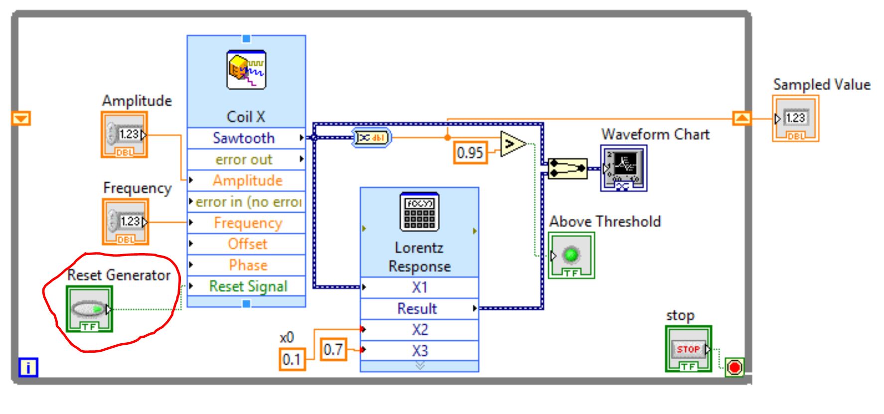
On figure 1 - Schematic of my installation with pushbutton "Reset Generator" below on the left.
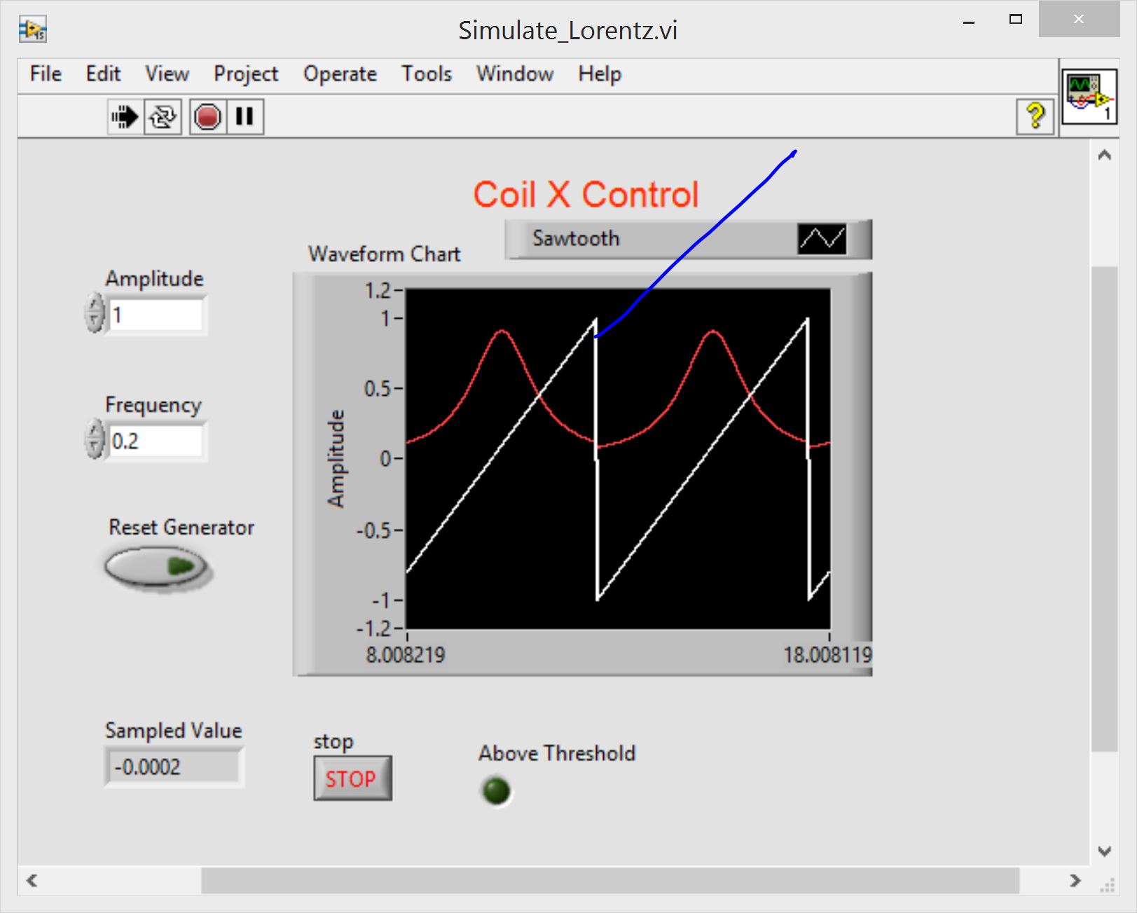
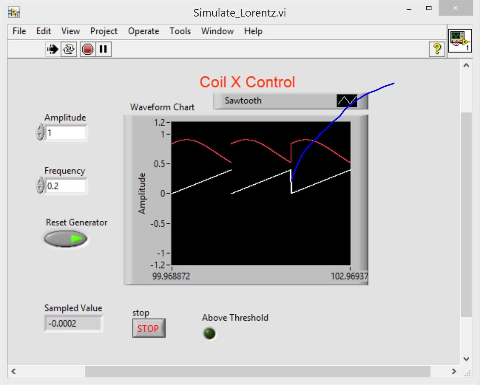
On Fig. 2 and Fig. 3 - the output of the 'Simulate Signal' block and some derivatives of signal with 'Reset Generator" OFF and WE accordingly.
As you indicate, in the case WE , the output is not 0.
Thanks in advance for the clarification
Pavel
Fig. 1
Fig. 2
Fig. 3
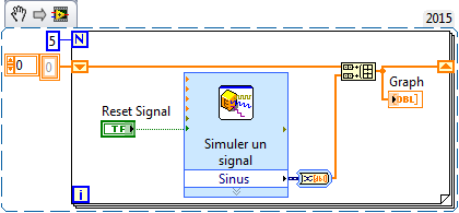
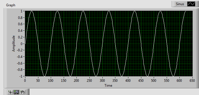
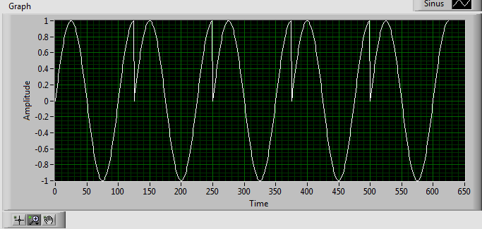
The reset is used to "reset" the phase of the signal to its default value when the value 'True '. If you leave the value of "reset" to "false" and you run the Simulator signal in a loop, you will get a contineous waveform, even when your signal Simulator does not generate a whole number of cycle (combination of signal frequency, sampling frequency and number of samples). If you set the "reset" to "true" the waveform will be interrupted (the stage will be set to its default value in each iteration).
Here is an example:
"RESET" = FALSE, see chart below:
'RESET' = TRUE, see the chart below:
-
Hello world
I'm trying to filter the noisy analog inputs of 10 channels (DC). I'm sampling of 100 samples/channel at 1000 Hz. My idea is to filter the data with a low pass filter (cut to 10 Hz 3rd order butterworth low freq) and then to calculate the average of each package of 100 samples. Finally, I would like to receive values at a rate of 10 Hz, which can be displayed on the front panel and be written in a file of measures.
My problem is the following:
The Express filter VI does not filter continuously after that the VI began. It seems to reset each time the loop runs. The table of 100 samples (white) before and after (red), the filter appear in the image "filterResponse". If I take the average of this table, it is of course less without the filter due to the transitory values between 0 and 0.025 s. I built a simplified version of my VI with only one channel using the VI "Simulate signal" and my concept seems to work well which is permanently (see "filterMeanExample.vi"). I get the idea that it might have to with the kind of dynamic data that is supported by many express VI. But since I'm on the VI KEITHLEY, I do not use the type of dynamic data. In fact, I had to convert a waveform data type to get a vehicle appropriate for the file of the measurement of its release.
I wonder how to keep the filter VI of reset each time that the loop runs.
My VI is rather large and contains the KEITHLEY 'Acquire signals' VI which most people do not have in their libraries, so I decided to show only the images.
Thanks for your help!
Phil
System: WinXP, LabVIEW 8.2.1 Professional
Thanks for the tips, I am set!
I used the VI of butterworth filter in the tool box to filter on the Panel of the Signal processing that accepts the type of table data. I put the variable ' init/cont' true to prevent the filter to reset its initial States to 0. I guess, it was my real problem before. The Express filter VI doesn't have this option, so I wasn't aware of this feature.
However, an image of the current value is attached.
Thanks again,
Phil
-
Hi I have measured data using a SELF-DIAGNOSIS device and that you have downloaded the log files as a .csv I have attatched below. I'm trying to read the 7th column of data (RPM) and display it on a waveform graph, read line-by-line to simulate driving real-time data. The interval between readings, I'm trying to achieve is 500 Ms because it is the time interval of readings on the worksheet. I'm finishing the two loops when rpm is equal to zero, as happens when the car is off. I have attatched the relevant section of my program below. Any suggestions would be greatly appreciated.
Thank you
Michael
There are two errors in your block diagram. First of all, as you read the entire table 2D in all at once (which is fine), you make a clumsy (pardon my language) job to make a line of programming. Once you take the first line of headers, you have the ideal substrate for a loop, which is made of elements of an array (lines) process, one at a time, using its tunnel of indexation.
The second mistake is to forget data flow. The loop, I mentioned, or the While loop you use, produced one at a time and points it at 2 Hz thanks to your expectation of 500msec. You want to give each point to your chart, but the picture is out of the loop, which means that there is No point until the loop ends.
Here's an easy Question - where you put the indicators in table of waveform? [Council - I said that "outside the loop is bad"].
Bob Schor
-
Hello
I am teaching LabVIEW. I want to delay a wave form and display it with the no delayed waveform. I used a delay in the examples. The output of the delay is thread (double waveform). Signal to simulate output is data Dynamics. My conversion of the thread (double waveform) Dynamics does not appear on the graph of a waveform. The VI is attached. Can anyone offer any comment.
It's displaying fine. The screen is hidden behind the screen of the second signal. Expand the Plot legend to display all three plots. Then toggle the visible property of the plot of the second and third plots.
Lynn
-
Continuously measure and write waveform using PDM
Hi all
I'm doing my thesis by using Labview 2010 (since this is the only version currently available in University
 ). I need to read and save data from the microphone (currently to simulate a signal because I need to make the program work first) then save and analise IT (has not reached this point yet). I tried to use the structure of the event in order to record and then play tdms files. But unfortunately it saves only a small piece, then I inserted while loop, so it will record continuously but the program is not responding after registration, I push and I can only manually close the toolbar it. Please does someone could help me or suggest that something since I'm not very good for Labview and any comment is welcome. Here's what I've done so now. I tried searching forums for a similar solution but did not find anything useful (some had a much newer version so I could not open). Thank you.
Hi and welcome to the forums,
The reason why you can not stop the waveform recording or exit the application is because you have the case of the events set to "lock the table until the end of the matter for this event" (in edition events). This means that LabVIEW will not respond to the user until the end of this structure of the event, but because you have the option to press the while loop stop to complete the structure of the event means that you have a blockage and abandon the VI.
The architecture of your application is not ideal - I highly recommend everything that takes a long time to execute within the structure of your event for the above reason (obviously you can uncheck lock as a quick fix Panel). I think I have a look at the design of producer/consumer model (events) (new... > model > frameworks) because it would be more appropriate for your application. You can manage your button presses in the structure of the event and have a state machine in the loop at the bottom for starting, running and stopping of your data acquisition.
The idea is that you don't do very little inside the event structure so it frees up the façade, but the messages (e.g. power acquisition data, quit the application) are managed by another loop.
I don't know if it comes in LabVIEW 2010, but there are examples of projects that include a project in 2012/2013 "continuous measurement and logging" which may be suitable for your application. There are also examples of the State machines and managers of messages queued.
-
Waveform behavior of strange graphics update
I have a strange problem with a waveform graph in a VI in LabVIEW 8.5. For some reason when our diagram must autoscale the y-axis, all of the graph will redraw. This causes a noticeable delay and is visibly distracting. At first, we thought it was a problem with the style of point, as we see only this question in our application by using a style that uses individual points for each data point, rather than connecting the dots with lines.
To test, I made a sample VI to ensure that he was not a problem of performance with any of our other codes and slipped and fell the graph of our application in a new VI. I made a simple pattern that simulates the data written on the chalkboard. I was a little relieved when I saw the same problem because it made me think that it wasn't our code that was the issue.
Then, on a whim, I decided to replace it with a 'new' waveform graph. After you set up a certain number of things, I tried to reproduce the behavior, and I can't! I tried to make the two graphs as identical as possible through all the settings, but I can't understand why it is shown the repainting issue, while the other does not.
I have included the two screws, and I'd love to know if others see the problem, and if anyone has an idea as to what is the cause. To see what I mean, turn the knobs Amplitude and prejudice to force the chart to repaint. GraphUpdateTest.vi will NOT show a problem, while GraphUpdateTest2.vi will be.
Thanks in advance!
-Ron
Hi Ron,
I could see what you're talking about, and I created a demand for corrective measures for this issue. Thanks for the bug capture.
-
Since the upgrade to 8.0, when navigation between screens, my computer screen becomes black for 1 second before the screen is redrawn. This happens regularly and is a major nuisance. It simulates a power failure. It does not happen with IE.
Here I answer to my problem: I upgraded my graphics card and the problem seems to have disappeared.
-
How to simulate a right CTRL key on a Satellite M30?
Hello!
I don't have a right CTRL key on my Satellite M30. But one of my frequently used desktop application need this key and redefine in the request is not possible. How can I simulate this right CTRL key on my laptop?
Hello
Read the user manual. There, I found the info that the key combination FN + Ctrl simulates the right CTRL key to extended keyboard.
-
Satellite L850-A845: simulate the middle button of the mouse on the touchpad
Hello
Is there a way to simulate 'the middle mouse button' on my laptop Pad?
I have Satellite L850-A845
Thanks in advance
Post edited by: handsah
Hello
I put t know if the touchpad software includes this option.
You should check this in the touchpad options.You can find it in:
Control Panel-> mouse-> tab advanced-> button Advanced settingsBut in my case, this option does not exist.
-
Viewfinder LUT vs exposure tools (Zebra / waveform)
Hi guys,.
Discussions on our new found access to MLUTs and the AE CINE was great, thanks for all the info fascinating so far. So forgive me if this has already been covered, but I have two questions:
(A).. .for MLUTs in the viewfinder to be of any practical, why use the waveform monitor and the Zebra reacts to the MLUT when applied, as opposed to the same as if the MLUT has not been applied to all? IE - as an image in the viewfinder as slog2 sgamut my Zebra / wave give me information of the exhibition which is very useful (next to my light meter) but when I apply, say, the REC709 MLUT of the VF, news of Zebra and waveform to adapt to the new image - so REC 709 points out, blow and my zebras tell me now that the parts of the image is blown... But I'm still recording to SxS cards like sLog2 sLog2 - so, in reality, this info is not get blown at all.
So what I mean: the REC709 MLUT is ideal to boost the brightness etc. in the viewfinder and makes the image easier on the eye than the image dark sLog2, but I always feel like my tools of exposure to expose properly for the image being recorded to the card (in this case sLog2). I hope that all makes sense... Accept others, or am I missing something here?
and the second point is:
(B).. .throughout all the upgrades for the camera by setting the number 2 zebras at 109% don't turn on for me in the VF, despite an image being obviously blown. No more than 108%, or 107%. However the zebras behave corectly to 106% and will show the 'Zebra lines' when the image is burned.
Is there a reason why 109% zebras does not illuminate, or am I missing something here too?
Thanks for all your comments guys - happy shooting.
Tom
-
How to open file audio waveform
We have a file on a USB audio waveform. iTunes will not play it... any suggestions or recommendations on another application to use or download? Thank you!
VLC download it here: VLC for Mac OS X
Maybe you are looking for
-
Cannot transfer files to the new WD passport external HD
I have a new ultra external hardrive WD passport. This is in addition to one I already like my time machine and another that I like a return to the top of this. Since then, I bought a 3rd to save some external files, my iMac and one of my hardrives
-
Audio lost when moving clips from browser to timeline
Let me repeat my question: Working on a project I must have done something wrong and now when adding clips on my calendar they transfer from the browser, but the audio is muted. In the browser the audio works fine but once in the timeline, it shows g
-
How to make another photo library the library of the system, the button is grayed out.
I followed the instructions on a Web site - off Photos, you press Option and on Photos. I chose the new library, but I went, when I go to Photos / preference / I don't press on use as Photo library system because it is grayed out. Any suggestion woul
-
Z570: Plugged in but not charging status message
Hello I recently had a computer laptop z570. I get status above message "trendy but no charging current. What is the reason for this? What is an adapter or battery problem or one other change of parameter to enable this I tried the 'Balanced' & 'High
-
HP Pavilion g6t-2000 CTO: dedicated GPU upgrade Possible?
My laptop has switchable graphics and I was wondering if I could update the map that was not integrated. I bought it three years ago naievely think it would be good enough for the games. The GPU is currently the only thing that keeps me from Fallout