Slow Signal acquisition
Hello
I'm still an inexperienced user and just started to compose the new laboratory in modules, the software Subvi. The file in the annex shows the arrangement. The problem is that writing and plotting are 50% faster, it should be. I.e. after 10 sec 5 seconds are drawn and written. I tried already to have writing file and the path in different loops, but the problem remains the same. I also ran an older code that has not all Subvi and there, data acquisition (score and writing) went as it should. So I guess the problem is buried in the code, but I'm not (already checked the forums).
I'm a bit under the pressure of time at the end of this program, and therefore a quick help is very appreciated.
Thank you!
RUF,
The fact that a part of the code is in a Subvi is not the problem. SubVIs have a very small ovehead which is totally negligible in your case.
I see several things that can contribute to your performance problems:
1. you save each other data point to the file and draw those XY graph between 0. Is - this intentional?
2 gain. you a point at once (per channel) and then write it to the file. This means about 50 DAQ bed and 50 written to file in the Subvi, another bed DAQ 50 and 50 entries on the chart per second. Writing to the file can be quite slow. Write faster that the eye can meet a graph of fornt Panel soon. Can you keep it up, or you get buffer overflow errors?
3. perform the calcuations inside the loop that never change losing time. Make a time outside of the loop. (rate from 1/100).
4. you take scalar, build them in tables an element, convert to dynamic data type, cross the XY Graph VI Express Build (which converts in wavefroms, then back to tables) by two points and then draw on XY Grpah 0. A fiber node would do most of this in a single step. But what is the value of a graph of a point?
Solutions.
1. define exactly what data you need to acquire, what data you need to back up, and what data you need to display. You specify that data loss is expensive. What is the most likely cause of data loss? Slow performance of your program? Power cuts? Something else? The data used while being acquired or only after the test is complete? I suspect the latter because you indicate you could write later if there is no risk of data loss.
2. consider architecture of producer/consumer for your program. This would have the DAQ bed in separate (producer) loop. The only other thing in the loop of the producer would be a queue or some other mechanism to transfer the data to the consumer hand strap. The loop of consumer would accumulate data and periodically written to the file and update the graph. Loops could (and probably should) run at different speeds. Look at the design of producer/Consumre models that ship with LV, how much have you read in each iteration of the producer and how often the consumer records in the file and updates the data graphic depend on the results of the proposal 1. I don't know the time wherever you have now is far from optimal.
3. clean loops. Loop iteration/frequency = (1/frequency) * iteration of the loop.
4 in the loop of the consumer shift registers will probably be how to collect the data for the chart and the file. You should never send the chart more points than there are pixels in the plot. Plot graph XY 0 has a width of the box 624 pixels. If you never send more than 624 points, LV will compress the data (in a way that is not good publicity) the number of pixels on the screen. So don't send tens of thousands of points on the graph. Insert in the table can cause problems with the memory allocations and speed when used in a loop. Use initialize the array outside of the loop and replace a subset of table inside.
Lynn
Tags: NI Software
Similar Questions
-
NOR-USB 9229: How audio signal acquisition?
Hello
It's one of those stupid beginner questions
 I use a module OR 9229 USB to capture the audio output of my computer line as follows:
-left line-out goes to AI0 +.
-right line output goes to AI1 +.
-land line out of is divided into two and goes to AI0 - and AI1 -.
What is the correct way of wiring?
In case it is, I have (I think) have problems audio signal acquisition. In the Measurement & Automation Explore, I creates a task for the acquisition of voltage AI0 (44100 Hz, etc.) -nothing is displayed on the graph when I run the task! (I have music running on the computer during the measurement) Otherwise, the 9229 flashes green, seems to be ok, auto test work, etc..
Someone has an idea what I am doing wrong?
Thank you!
Hi acgrama,
That sounds like it should give you a signal any (not an empty graph or a flat line at 0 V), but the USB-9229 is not very suitable for audio:
- The USB-9229 to entry level is of +/-60 V. A line level audio signal will use a small fraction of that. Of the USB-9229 precision and plug noise are adequate for your application?
- The USB-9229 can't acquire them exactly 44.1 kech. / s. It supports some 50 kech sampling frequencies. / s divided by a number between 1 and 31, as 50 kech. / s, 25 kech. / s, 16.7 kech. / s and so on. When you specify a sampling clock DAQmx not taking in charge, he is forced to the top supported next, which in this case is 50 kech. / s. (you can read back the SampClk.Rate property to see what DAQmx forced the rate to.) For 44.1 kHz audio to USB-9229, you will need to re - sample the acquired data (which are specific to the programming environment).
Assuming that you're just trying to do it for learning or experimentation, here are a few ideas:
- Is the line connector configured as an output line? Many mothers today have reassignables audio connectors.
- The volume of the source (wave, CD, whatever) high enough?
- On the graph, is scaling auto turned on? If you display data in a table instead, are the numbers exactly 0 or any close?
- The output of the line works if you are connecting to another device that is designed to handle signals to line level?
- If you connect a battery (AA, 9V, whatever) for the USB-9229 instead, read the Max supply voltage?
Brad
-
Slow signal on iPhone 6 sec more
Hello
I have a new iPhone 6 s more, I find that it is slow to get a signal to my service provider and once I have send an SMS after using the internet several times, it is very slow to send the message. Kindly advice me. Thank you very much.
Is your on LTE, 3G or 2G cellular data network?
You can check the power of the signal to other iPhones at this place?
It has always been like that?
-
IM using usb-6009 input signal acquisition
IM acquirng a domain controller of the signal in the analog input (CSR), a volt of entry in 1.9 ports V is read on the (ai0) port of entry when I use a multimeter to read the value and at the same time I used an indicator to show the data read in the port of entry in my code, the led will turn to 2.5 sometimes 4V... If any body could help me this please answer me...
I have another doubt too, I read a document in which they mentioned everything using the CSR that the positive end of the source must be connected to the analog input channel and the negative end to the ground in the acquisition of data... but its im using a dc signal I don't have how to connect and what to do...
Hi Lisette,
I Don t know what could happen. However, this could be a wiring problem.
First of all, if you read this signal I'll recommend over the analog GND with your digital GND. You also this thread from the mass of the signal.
Another thing, you might be able to do is to measure in differential mode, you can connect your 6009 NOR as the multimeter.
Here's a tutorial that may be useful for you: http://zone.ni.com/devzone/cda/tut/p/id/3344
Here are also a few KBs talks about what concerns you. Take a look to see if something, it might help.
http://digital.NI.com/public.nsf/allkb/95CC0CB11D7DF3D18625712E000C4ABD
http://digital.NI.com/public.nsf/allkb/C7C4AB4BD256EF0386257013001650E7?OpenDocument
http://digital.NI.com/public.nsf/allkb/C7E181E51E4299FC862570A700604141
Finally, don't forget to use the Op Amp in follower configuration to avoid damaging your 6009.
I wish you success!
-
Virtual oscilloscope; Slow Data Acquisition (limit of 5 Hz)
Hello.. I tried for a some time now schedule a virtual oscilloscope using the software or Labview and materials acquisition of data USB-6009.
This has been my best attempt to date: http://www.andthenbam.com/FievelScope.vi
I seem to only be able to measure frequencies up to 5 Hz, then the frequencies of signals begin to repeat themselves. I am aware that this device is capable of a MUCH faster speed. I'd appreciate it if someone could take a look at my VI and recommend a solution.
Acquisition mode: 1 sample (on request)
Buffer: 100 samples
I failed to raise other modes of acquisition work. Help, please!
Here I explain my problem:
http://www.YouTube.com/watch?v=k8oI9mL8ZD4
Ty
Your problem is that you are setup to do one sample on request. This means that you count on the loop to set your frequency of acquisition. You probably really want to continuous samples with a rate that is much higher, depending on what you are trying to capture.
Looks like you're trying to sample every 100ms. It is 10 Hz. Therefore Nyquist function, 5 Hz is the highest frequency that you can enjoy. Anything more than that will alias down in the 0-5 Hz range.
-
How to operate an Express-Signal acquisition with the windows cmd.
Hello
I try to make a measure of consumption Signal Express. But I want to operate this measure with a command prompt. I don't find the solution in the user manual.
Do you know if it's possible?
Thank you
Thank you very much. We head to Labview, which should solve the problem.
Kind regards
François
-
Signal acquisition of voltage AC using NI 9206 9205 and cRIO
Hello. I have difficulties accurately acquire a signal voltage AC using a module OR 9206 and cRIO. I'm looking to acquire signals of tension of the two types of current transformers Magnelab: divide the rope and the base. In Labview, I first fill out an array of size 2 500 with the signal of the sensor (DIFF mode), and then calculate the RMS of the table. For the core of split CTs, I'm able to acquire exactly reading the correct voltage (verified by measuring the match on the line using a power Analyzer Fluke 434 amp. For the CT string, however, using the same method of table/RMS, I am unable to gain precisely the correct voltage reading. Measure the amp on the line using the Fluke 434 PA, good the CT string tension should be 0.05v. Using the 9206 (DIFF mode), the RMS of the array gives a reading of 0.071 voltage. Now the interesting part is when I measure the voltage by using two different True RMS DMM, I get two different readings. A multimeter, a Klein CL2000, reads the voltage in 0.05v. Other multi meter, a Fluke 189 reads wrong to 0.071, the same that I get using LabView and NI 9206 release. I guess the question is how the Klein interprets the signal differently Fluke 189 and the NI 9206 via LabView module. A difference between the split-core and rope CTs, is that the rope CTs require a power external power supply 12-30 v AC or DC. I'm providing 12v DC. I tried several AC and DC voltages and still get the same wrong result. I am quite sure that it is not a question of power supply, although perhaps the integrator in the rope is the creation of a single signal. Any ideas? I appreciate any input.
Thank you
J.Grant
AK2DM:
Update - found solution
-
Hello
I use a CompactDAQ to measure signals. I'm reading 10 signals: 2-channel 2-line of NI9219 and 8 channels of thermocouple (thermistor) resistance. I'm in LabVIEW 8.6. I read a sample in all channels once and then read another sample. I don't know why I can't get a sample of all channels every 3 seconds. The hardware specifications are better than this. Please see attached program.
Ryan
Hi Ryan,
There a number of things you can do to improve your performance.
First, you use the NI 9219 in synchronization of high resolution mode. That puts your time of converstion to 510ms for all channels. Was - this intentional?
Second, are you double-check and engaging your task with each iteration of your loop for. Since there was no explicit state transition, the task will relax after each read and you must configure the task again before each next reading. Put a beginning vi just before your loop for. You leave your task in the executing State and greatly increase your performance.
Finally you use at the time of the request. Is that what you want? If you try to go as fast as possible on the NI 9219, you can consider using the hardware timing. In this way the samples of the device in the background and you can read the data when it is available. Note that you must pay attention to max speed. If you use material timing and the sample at a faster pace than your NI 9219 reports, it will return repeated data.
-
USB-6009 slow output signals using SignalExpress - error 200077
We have a Council of USB-6009 and Signal Express version 3.5.0
We want to generate low-frequency, analog and digital outputs to simulate some slow movement process.
We have created the signals and their generated as output, put when we RUN the project, we get error 200077, which seems to indicate that we must use On Demand distribution of signals.
If we choose On Demand, then the generate DAQmx says we have a missing entry.
So, what method should be used with the slow USB-6009 to generate box (.01Hz and slower) analog and digital outputs?
These are 2 of the projects, we tried - using On Demand, N samples, continuous, internal, and external triggering etc..
Thanks adavance for your help...
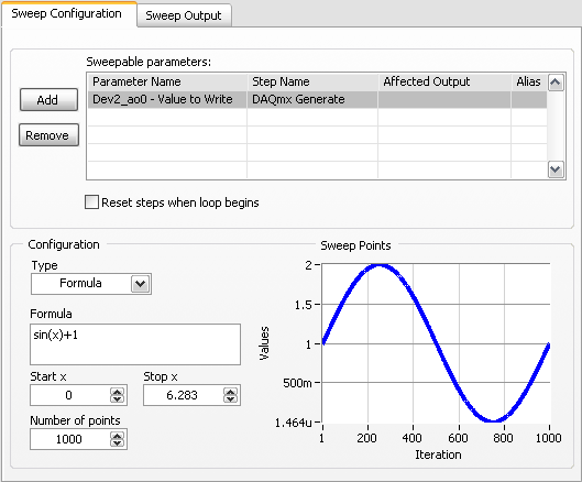
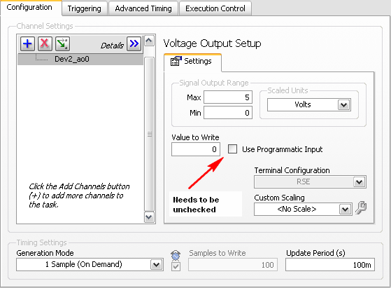
Welcome to the forums of Steve,
I have good news for you. I played a bit with the sweep and actually got a code facing up to generate a slow signal. I went and tested it with the 6009 and he was able to run without any errors. I joined here, but if you have to open (or anyone else in the future), here are some screenshots of how it works. If this works, feel free to make the forum as resolved while others can locate a solution a little easier in the future.
Scan Configuration:
DAQmx Config:
-
I am writing the control software for a system that uses RF (clocked at 72 MHz) as a major component. None of our signals have harwdare filters and software I am sampling 100 samples at 1 k Hz. I have on average these samples and update every 250ms.
Using a language I can understand, can someone help me understand how RF may influence our signals and what options I have to filter this noise (harwdare and software). Or at least point me to a good resource.
Doug,
Here's the ME version of RF interference. The combination of transmitter/antenna radio creates electromagnetic waves in the space around the antenna. Think of dropping a stone in a pool of water. The wave analogy is reasonable for the basic understanding. A leaf floating on the pond goes up and down with the wave. If you put a float on the water and connect to the Mainland by a gearbox, you can extract energy from the waves.
In your DAQ system two things are necessary to produce interference. 1. the RF wave must be coupled to the system. 2. the RF energy must reach a point where a non-linear device converts the sine waves of very high frequency in a form which allows to measure the low frequency DAQ system. (2.a. There are a more complicated way interference can occur without a nonlinearity - subsampling).
How the coupling can occur? The wavelength of an electromagnetic signal in free space is the speed of light, divided by the frequency. For 72 MHz the wavelength is 4.17 m. A wavelength of antenna 1/4 long can couple to electromagnetic waves very effectively. Y at - it wire in your system about 1 meter long? USB cable? It is likely that you have some very nice antennas. If the voltage from one of these antennas reached about 0.5 V, it will be sufficient to cause the internal diode junctions in any device of semiconductor (such as amplifiers, analog/digital converters and multiplexers) of lead. This conduction is non-linear and produce a DC voltage out to the RF input. This tension Gets the sum (with unknown polarity) with the signals you want to measure, prodcuing errors.
What can you do about it? Disable the transmitter will not solve the problem, but because it is needed for other purposes, is not an option. The signals of interest being very low frequencies, it should be fairly easy to eliminate parasites. Three general principles apply. First is to eliminate the source, which has already been ruled out. However, check if the transmitter power can be reduced without compromising the performance of the RF System. Second is to reduce the coupling. If possible, keep the transmitting antenna as much as possible to the source of your slow signals and threads of connection to your data acquisition system. The orientation of the antenna and son can help too. There are too many combinations to try even give general guidelines on this without more information on the physical configuration of your system. Armor is a big part of the principle of coupling reduction and works well at 72 MHz. All the sons of your signal sources for the acquisition of data and data acquisition to the computer must be shielded. Should be based on the shields. Just make sure that you don't create ground loops in the process that can lead to other problems. Connect everything to a pattern with a 'star' grounded to System. The third principle is to reduce the signals interfere by filtering. I would try to put a ceramic capacitor of 100 nF for each signal line to the mass input on the DAQ hardware, keeping the capacitor leads as short as possible. If your sources of signals have a very high impedance or inductive, you might have an EE assess suitable filtering. The benefits of the capacitors are: cheap!, simple to install, will reduce RF interference over a wide bandwidth, require no development and are generally quite effective.
The problems are depending on the severity, it can be quite simple eliminate your interference or it might require a major overhaul of the entire system.
Lynn
ADDRA Consulting, LLC
-
Rapid acquisition with PCI-5152
Using the card PCI-5152, I try to make an acquisition of signal 2 seconds with a loop clocked for 2000 forms of waves, or 1ms by acquired signal. The example attached to this message does not reach this speed and would certainly be optimized. I am looking for any opportunity for improvement of this loop.
Hello
In your VI, he y ' has several points that bother me and that would be good to improve:
- The loop of the of the in UN file to the writing: strongly, that slowed your acquisition, because access to a hard drive is quite ready.
- Operations and different manipulations on your signal: it slowed down also the acquisition.
Pour it, I you Council out the ' writing the file of the loop, and perform your operations after the acquisition. "
Pour do this, we recommend using the architecture of programming say "producer / consumer. A loop to load manner the acquisition, while the second is in charge of dealing with the different operations on the signal. Communication between the two loops using a FIFO or queue waiting.
I you Council to look at this example:
http://decibel.NI.com/content/docs/doc-2431
Kind regards
-
How to acquire the generated signal?
Ladies and gentlemen, I am a novice in LabVIEW even if I practice solving problems more or less difficult, I got NOR cDAQ-9178, possess an entrance connected with output channels and after a plan of work on the signal acquisition and production separately, I decided that I could successfully combine the two plans and get the system of acquisition of generators. Hell I didn't know it wouldn't work. There are probably many things im doing wrong in this case, so no finance or support directly with the .vi is attached to the message would be so appreciated. Thank you.
One thing I think is that your generated frequency is not suitable with #S and Fs you have configured. Try #S = 10 k and Fs = 100 k.
-
County of the edges of the AI of signals with the module 9221
Hello
I'm counting the edges of a signal to HAVE acquired with a module 9221 on a cDAQ. The average rate is about 1 kHz.
I'm with 10 kHz signal acquisition, but do not get the right amount of edges.
Is there a solution for this problem. I know, of course, it would be easier to use a CTR-modul but my signals does not match the plug.
Thanks for any help
Yves
Hi Yves,
There is a method to count planking of an analog input. See the link
http://digital.NI.com/public.nsf/allkb/B472ABA1362F44328625729C0041A8B1?OpenDocument
I hope this will help you.
Best regards
Sascha Egger
Technical sales engineer
-
How to reduce the noise in an acquisition of data USB-6251
Hello world!!!
I have a few questions about a system that I have developed using a data acquisition OR usb card 6251. The pressure control system.
First of all, the signals are acquired using an Omegadyne pressure transducer. (Typically, the signals are between 0.1 mV and 38 mV, pressure is between 0 to 50 lb/PO2). The transducer is connected to the usb-6251 daq card (I use pinout of the 1 and 2 for the signal acquisition, also, I have a 100 K resistor between pin 2 and 3) and the card is connected directly to the computer. In addition, I have an omega counter, I use it only to see pressure on the screen. But long term, it will be useless.
One of the problems I have found is the noise, the measured voltage values change much. Even if the figures in the player screen do not change so much... (or do not change)
The system should regulate the pressure so if every second it changes a lot, the system did not work properly. How can I make the technical more similar to that of the meter? In the labview program that I use, I use a block 'base DC', he reduced noisy signals a lot, but not enough that experience, I need more stable values.Thank you
I don't mean in the /manuals of broaching and do not open .doc from unknown sources files (a chart single .png is fine ;-))
However, I guess you already measured in differential mode and the 100 k is a path for the currents of polarization forever
The reason why your counter is stable can be the fact, that she has a generation to filter low pass (on average) with a big enough constant time.
First things to do:
You did it that there is a filter anti-aliasing suitable for your sampling rate?
Read the signal on at least 100 ms (120ms in line 60 Hz) possible higher sampling rate and take a look at the signal (and display a chart as a .png or .jpg image)
This will give you an idea how the signal looks the same. Then you can choose a filter according to your system and the signal or other investigations to do not even catch the noise (groundloops, protection...)
You can use an example on the screws or the testpanel to the MAX for this measure. (Personally, I prefer a similar scope :-))
-
choice of the model of design for data acquisition system
Hi all
I have a problem on the selection of the model design / architecture for a data acquisition system.
Here are the details of the desired system:
There are data acquisition hardware and I need to use by looking at the settings on the user interface.
the period of data acquisition, channel list to analyze must be selected on the user interface. In addition, there are many interactions with the user interface. for example if the user selects a channel to add scanlist, I need to activate and make it visible to others on the user interface.
When the user completes the channel selection, then he will press the button to start the data acquisition. Then, I also need to show the values scanned on a graph in real time and save them in a txt file.
I know that I can not use producer consumer model here. because the data acquisition loop should wait for the settings to scan channels. and it works on a given period by the user. If the loop of user interface makes higher then loop (loop data acquisition) of consumption. This means that queue will be bigger, larger. If I use notifier this will be some data loss comes from the user interface.
y at - it an idea about it? is there any model of design suitable for this case?
Thanks in advance
Best regards
Veli BAYAR
Software for embedded systems and hardware engineer
Veli,
I recommend the model producer/consumer with some modifications.
You might need three loops. I can't tell for sure from your brief description.
The loop of the User Interface responds to the user for configuration entries and start/stop of acquisition. The parameters and commands are passed to the Data Acquisition loop via a queue. In this loop is a machine States that slowed, Configuration, Acquisition and stop States (and perhaps others). The data is sent to the processing loop through another line. The processing loop performs any data processing, displays the data from the user, and records to file. A registrant can be used to send the Stop command or stop the loop of the UI for other loops. If the amount of treatment is minimal and the time of writing files are not too long, the functions of processing loop might be able to happen in the case of the UI loop timeout structure of the event. This makes things a little easier, but is not as flexible when changes need to be made.
I'm not sure that there is a type of design for this exact configuration, but it is essentially a combination of the models Design of producer/consumer (data) and producer/consumer (events).
Lynn
Maybe you are looking for
-
New drivers for Qosmio X 870 and drivers BETA for Windows 8 available
Hello Suitemy previous Strip rolling and look in my endless Toshiba drivers Idiscovered that the Toshiba support site we posted divers for Qosmio X 870. Also rejoiceThere are drivers (in beta) for Windows 8 in 32 and 64 bit flavors. Andnot only for t
-
No noise (regular or touchpad) on my iPad 2 Air.
Lockscreen & keyboard sounds are turned on, mute is not on. Sound works only with headphones (for applications), but YouTube works fine without them. Volume control does not "headphones" are used when they have been removed (I had this problem some t
-
Why my microphone is distorted when I start my tablet PC?
Speech recognition does not work when you start upward because the microphone level is full 2/3rds and stuck there. By 'level is 2/3rds complete', I mean the level indicator in the comments box or the speech Properties window shows 2/3rds full. Usu
-
Windows Vista tm Home Prenium product key you typed is invalid for Activation"
I just did a system restore and connected but has a window pops up saying "The Windows Vista tm Home Prenium key you typed is invalid for Product Activation" but I do not type anything and I do not know the product key and I don't know what to do
-
10.2 beta of GeoPolyline problems - duplicate
EDIT: Posted prematurely trying to add the source code. Would be grateful if someone could point me in the right direction on how to enter a post source. Someone at - he had GeoPolyline or GeoPolygons to work on a plan, or is it an example of program