Slow data acquisition speed
Hello
I use a CompactDAQ to measure signals. I'm reading 10 signals: 2-channel 2-line of NI9219 and 8 channels of thermocouple (thermistor) resistance. I'm in LabVIEW 8.6. I read a sample in all channels once and then read another sample. I don't know why I can't get a sample of all channels every 3 seconds. The hardware specifications are better than this. Please see attached program.
Ryan
Hi Ryan,
There a number of things you can do to improve your performance.
First, you use the NI 9219 in synchronization of high resolution mode. That puts your time of converstion to 510ms for all channels. Was - this intentional?
Second, are you double-check and engaging your task with each iteration of your loop for. Since there was no explicit state transition, the task will relax after each read and you must configure the task again before each next reading. Put a beginning vi just before your loop for. You leave your task in the executing State and greatly increase your performance.
Finally you use at the time of the request. Is that what you want? If you try to go as fast as possible on the NI 9219, you can consider using the hardware timing. In this way the samples of the device in the background and you can read the data when it is available. Note that you must pay attention to max speed. If you use material timing and the sample at a faster pace than your NI 9219 reports, it will return repeated data.
Tags: NI Hardware
Similar Questions
-
Virtual oscilloscope; Slow Data Acquisition (limit of 5 Hz)
Hello.. I tried for a some time now schedule a virtual oscilloscope using the software or Labview and materials acquisition of data USB-6009.
This has been my best attempt to date: http://www.andthenbam.com/FievelScope.vi
I seem to only be able to measure frequencies up to 5 Hz, then the frequencies of signals begin to repeat themselves. I am aware that this device is capable of a MUCH faster speed. I'd appreciate it if someone could take a look at my VI and recommend a solution.
Acquisition mode: 1 sample (on request)
Buffer: 100 samples
I failed to raise other modes of acquisition work. Help, please!
Here I explain my problem:
http://www.YouTube.com/watch?v=k8oI9mL8ZD4
Ty
Your problem is that you are setup to do one sample on request. This means that you count on the loop to set your frequency of acquisition. You probably really want to continuous samples with a rate that is much higher, depending on what you are trying to capture.
Looks like you're trying to sample every 100ms. It is 10 Hz. Therefore Nyquist function, 5 Hz is the highest frequency that you can enjoy. Anything more than that will alias down in the 0-5 Hz range.
-
acquisition of data high-speed and simultaneous sampling
I'm quite familiar with the coding for NOR-DAQ boards in Labview. What worries me with labview, is that each tick is about milliseconds. I intend to retrieve the data simultaneously from 32 channels at 2 MS/s/chan using SMU 6368 s. Wouldn't not possible to enter data, on average 20 to 50 samples to get a unique value, perform simple algebraic manipulations on it and send it to the PC / software to approximately tens of kHz? We already have labview code to perform similar tasks, but it is quite slow and limiting the rate of experience. I said that Simulink is slightly better than Labview in this regard, but suffers a poor user interface and that if something C/C++ offers the ability to perform at high speeds with the same cards OR data acquisition. Could someone advise me please on this issue?
You can use your PC! You can use a PCI/PCI-e card as the interface to your computer and it should work perfectly. Take a look at these pages (http://sine.ni.com/nips/cds/view/p/lang/en/nid/10389) for more information.
-
Treatment of LabVIEW data and high speed data acquisition C
Hi all
I am designing a data acquition VI high speed of 3 cards acquition of data at the maximum speed. Data cards are PCI 2517 Measurement Computing. The sampling frequency for each card is 1 M samples/second, if the total sample of M 3/second of three cards. Problem is the LabVIEW drivers and the screws provided by the provider works very well just for a single card at maximum speed, but does not support multiple cards at maximum speed. Their technical engineer advised me to write code in c#, C++ or VB.NET for this data acquition high speed. If I use C forever, I would like to use LabVIEW for processing of the acquired data to data acquisition. I came across a few examples that suggest the creation of dll C code and then calling it a LabVIEW. But those who have programs simple and none of them speak in C data acquisition. My questions are,
1. is it possible to call a C data acquisition program high speed of labview and not work in any kind of present of buffer overflow?
2 would it not simple best to use labwindows CVI?
3. is there another alternative solution that I'm missing?
I'll appreciate all the entries.
Thank you!
Nilesh-
It's pretty easy. Arguments for CINrun must match wiring. You can wire your CIN function block and say LabView to generate the C interface code to begin.
Here's my pairs for the ASIO audio project.
All the best,
Terry
-
Change the speed of data acquisition
I record the temperature using a PSC-2120 (cFP-TC-120 + capable). Could someone please explain me how to slow the acquisition of data to make each minute rather than each MS that's for two reasons. First the data file are produced get so large that excel do not all data from a spreadsheet and Notepad can not open them. I had a .lvm file which was more than 700 MB of the day to the next. Second, the data is displayed on a graph when it is saved (left hand on the vi graph), but he is drawn as a variant rates. Sometimes it's every millisecond, others it's every few seconds.
I enclose my VI, but I can't reach my text file is too lig must be downloaded (it was after 10 min data recording)
Thank you
Chaz
Hi Chaz,
Thanks for the post and I hope that your well.
To change the rate of datalogging, you will need to use the timing of the loop. You can do this with a (better) timed loop or with vi timing structure (for example, wait until the next multiple) in the loop (good). This knowledge base article, he explains in detail,
How to set the analog input of my FieldPoint Modules rate?
http://digital.NI.com/public.nsf/allkb/3DCBB324D23FD637862571320066AA7A?OpenDocument
Hope this helps,
-
How to measure the angular velocity, the angle and trigger using a gyroscopic sensor breakout board and LabView data acquisition?
There is a single channel data acquisition code which measures the angular velocity, angle and flexibility using a gyroscopic sensor breakout board and acquisition of LabView data attached to this, I need a help to creat two-channel data acquisition code?
Hello
Attached is a vi that you can use in order to read the measured angular position of an encoder.
If you need more examples on the tasks that you can develop with NOR-DAQmx and LabVIEW, you just need to open LabVIEW and click Help > find examples > Input and Output material > DAQmx > entry counter.
Kind regards
-
How to increase the speed of data acquisition?
Hey, currently I using 6210 OR of data acquisition and control switch. I used labview to periodically check the 7 switches and read data from 7 channels in the meantime (1 sample on request). I ran 70 loops for 10 groups of data, the cost of the time looked like 2.2 seconds.
I would like to end a 700 loops in 2 seconds, is it possible to improve?
Thank you
PEM
Look at the Terminal stop of the DAQ Assistant Express VI. You are starting and stopping of the task for the acquisition of data on each iteration of the loop.
Starting from the help file:
Stop
Specifies to stop the task and release device resources when this Express VI ends execution. For ongoing tasks, this entry is FALSE by default, which means that the task is running until the application terminates. To stop the task, you can use the device again in the same application, wire control wire you the Conditional stop this entry to the same terminal of the while loop. For single-point and finished tasks, this entry is TRUE by default, which means work stoppages after all samples are acquired. To optimize the performance of single point when using this Express VI into a loop, wire control wire you the Conditional stop this entry to the same terminal of the while loop.
Also from the help file:
Continuous single point of entry or exit, the of VI Express DAQ Assistant cannot allow optimal operation. See Acq & chart voltage-Single Point optimization VI in examples\DAQmx\Analog In\Measure Voltage.llb for an example of techniques to create more powerful applications, single point of I/O.
-
Several timers loop data acquisition
Hi all
I am developing a VI for FPGA Deployment. My equipment consists of a chassis/controller for cRIO-9072 with module 1-9211 thermocouple, card SD-1 module, 3-9215 HAVE modules and universal modules 2-9219. I will collect data of two thermocouples on the 9211, 14 channels on 9215 channels and 6 on 9219 modules. This system communicates to the host via ethernet.
I have prepared a vi (see attachment), which used two DMA FIFO for writing data to data acquisition at a different speed. I will be sampling the s and 9211 9219 much more slow (500ms by samples), than other channels (40 ch/kech. / s). Currently, my FPGA vi trying only to taste two different modules. When I run the present on the host vi and try to read the data, I get only extracts of the data at different intervals. If either of her would reveal latency with the connection or the host vi failed to refresh quite quickly? I am relatively new to labview, so any help is appreciated. Thank you.
Gaussy
Hi Guassy,
There are a few things that you need to change:
(1) you must separate your acquisition in the FPGA in two separate loops if they have to operate at different speeds. As it is, probably will run at the slower speed of the two parameters.
(2) you must do the same in your VI in real time, or set up the DMA readings so that they will be read at the same pace. For example, suppose that a single module acquires 1000 hz and the other at 200 hz. If you want to read 100 samples from the first module (so your reading will occur at 1000 hz / 100 samples = 10 hz), you will need to read 20 samples from the slower module, so it is synchronized with the first module.
(3) your timeouts are too short on your DMA readings. Your slow acquisition is 500 us. It will take 50 ms to read 100 samples requested, but the delay is set for 10 ms, so 4 times over 5 playback will return nothing.
(4) you use graphics and no graphics. A chart will only show the current data buffer that was written for her. Refresh rate of the façade is nondeterministic, so that you can't see every update. If you use a chart, the chart will record all data written on it to the indicated depth (default is 1024 elements).
Also remember that you can have three FIFOs DMA between the host and the target FPGA, so use them wisely. It is often easier to perform your purchases on the FPGA at the same pace and send them through the DMA FIFO even in VI in real-time. If you need a few channels to connect at a lower rate, you can always throw the excess samples (there are some decimate wave screws that are perfect for this).
I hope that helps!
-
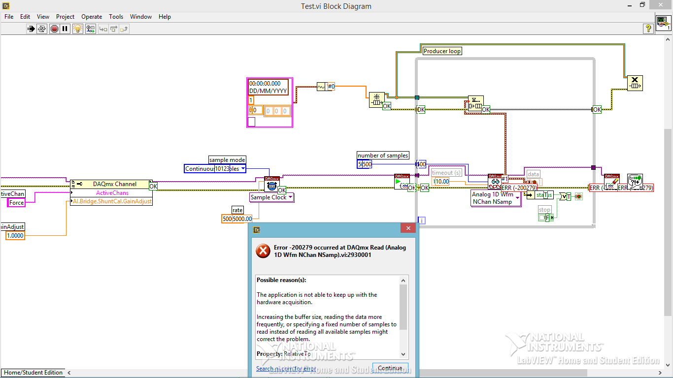
Code error-200279 for data acquisition
Hi all
I am trying to build a small program of data acquisition, but I get a 200279 error telling me to increase the buffertime. What I am doing wrong?
Andersson wrote:
No, you're right. I don't get the error, I turn off highlight execution.
It seems so. I did not understand why he would come with an error during the audit of the code with the bulb. It seems like what I discovered on www.ni, one can avoid the error of initialization of certain data for the chart.
Not sure if I got it 100% correct however. Here is the link:
http://digital.NI.com/public.nsf/allkb/A647A1BE3DA8336786257AAA0066B45B
I don't have any other loop in the installer. I'm sorry for the confusion with the name 'producer loop. It's the only loop in the code, I deleted the rest to refine the error.
Is the conclusion that the program is good? Or do I have to do something to remove the error?
The table has nothing to do with your error. It's strictly highlight execution.
When you configure a continuous sampling, start the collection of data at a given flow rate. It is so big a configuration of the buffer. There is an article that tells how much room it is exactly, but for the sake of argument, let's say 10 seconds worth of data. In normal execution, your code runs pretty quickly that she is able to empty the buffer as soon as the data are acquired. But when you enable execution of climax, your VI slows down to a crawl so that he can show that you step by step what is happening on each wire. Your data acquisition always occurs in the background. Execution of idle is to take much longer that data are acquired. Within one or more loop iterations, you have filled the buffer and get the error message.
You cannot use point culminating performance when you use a device of data acquisition in this way (or VISA ports either) where data are sent continuously at a speed that is independent of speed, the code is executed.
-
Hello
I'm still an inexperienced user and just started to compose the new laboratory in modules, the software Subvi. The file in the annex shows the arrangement. The problem is that writing and plotting are 50% faster, it should be. I.e. after 10 sec 5 seconds are drawn and written. I tried already to have writing file and the path in different loops, but the problem remains the same. I also ran an older code that has not all Subvi and there, data acquisition (score and writing) went as it should. So I guess the problem is buried in the code, but I'm not (already checked the forums).
I'm a bit under the pressure of time at the end of this program, and therefore a quick help is very appreciated.
Thank you!
RUF,
The fact that a part of the code is in a Subvi is not the problem. SubVIs have a very small ovehead which is totally negligible in your case.
I see several things that can contribute to your performance problems:
1. you save each other data point to the file and draw those XY graph between 0. Is - this intentional?
2 gain. you a point at once (per channel) and then write it to the file. This means about 50 DAQ bed and 50 written to file in the Subvi, another bed DAQ 50 and 50 entries on the chart per second. Writing to the file can be quite slow. Write faster that the eye can meet a graph of fornt Panel soon. Can you keep it up, or you get buffer overflow errors?
3. perform the calcuations inside the loop that never change losing time. Make a time outside of the loop. (rate from 1/100).
4. you take scalar, build them in tables an element, convert to dynamic data type, cross the XY Graph VI Express Build (which converts in wavefroms, then back to tables) by two points and then draw on XY Grpah 0. A fiber node would do most of this in a single step. But what is the value of a graph of a point?
Solutions.
1. define exactly what data you need to acquire, what data you need to back up, and what data you need to display. You specify that data loss is expensive. What is the most likely cause of data loss? Slow performance of your program? Power cuts? Something else? The data used while being acquired or only after the test is complete? I suspect the latter because you indicate you could write later if there is no risk of data loss.
2. consider architecture of producer/consumer for your program. This would have the DAQ bed in separate (producer) loop. The only other thing in the loop of the producer would be a queue or some other mechanism to transfer the data to the consumer hand strap. The loop of consumer would accumulate data and periodically written to the file and update the graph. Loops could (and probably should) run at different speeds. Look at the design of producer/Consumre models that ship with LV, how much have you read in each iteration of the producer and how often the consumer records in the file and updates the data graphic depend on the results of the proposal 1. I don't know the time wherever you have now is far from optimal.
3. clean loops. Loop iteration/frequency = (1/frequency) * iteration of the loop.
4 in the loop of the consumer shift registers will probably be how to collect the data for the chart and the file. You should never send the chart more points than there are pixels in the plot. Plot graph XY 0 has a width of the box 624 pixels. If you never send more than 624 points, LV will compress the data (in a way that is not good publicity) the number of pixels on the screen. So don't send tens of thousands of points on the graph. Insert in the table can cause problems with the memory allocations and speed when used in a loop. Use initialize the array outside of the loop and replace a subset of table inside.
Lynn
-
motion control for vertical actuator and data acquisition
Hello
I am a researcher (a branch of civil engineering) geotechnical engineering and I have very little knowledge about the acquisition of control and data motion, so would need a lot of help from the experts OR. I have only knowledge base on these 2 aspects based on my reading of some materials on the Web site of NOR and youtube videos, so I hope that you bare with me
 . Here are my questions:
I am trying to build an actuator which will be used to push a probe (a penetrometer with a load cell to measure the resistance of a soil sample), resembling the concept, photography in the attached file. I need to have these criteria for my system:
(1) actuator, which can push the probe at speeds between 0.01 mm/s - 300 mm/s with precision and move the probe cyclically (upwards and downwards) in the vertical direction
(2) load expected on the probe into the ground range: 0.02kN - 6 kN.
(3) necessary to get the load cell load data and the speed of the probe.4) able to control the actuator to a PC (speed and posotion) and monitor data from transducers and data log time even the transducers.
Guess my beginners is that I will need:
For orders:
(1) software - LabVIEW and NOR-motion assistant(2) controller - NI PCI-7342
(3) driver/amplifier - analogue servo AKD Drive
(4) motor - motor brushless servo AKM
For the acquisition:
(1) software - based LabVIEW development systems(2) amplifiers or other device - no idea what type on the conditioning of signals
(3) data acquisition device - no idea what type
Since I'm a beginner, is - that someone might recommend components (hardware and software) for the control and data acquisition. I'm on a tight budget, so I thankful if someone could help me to recommend components good enough to build my system.
Thanks for your help.
At these rates, you will need to run the sensor for the cDAQ. You can configure the analog output on the Tritex nationally on the position. There is an adjustable filter that you can set in order to get a clean enough to 300 Hz signal. When you learn about the Tritex, make sure that let you them know what comms and e/s that you want to use. If I remember, not all options have worked together. The analog output may need to be my, but you can put a resistance through the acquisition of input data to get the voltage instead. I don't remember all the details. You should really not too much on the Tritex/LabVIEW side. You will send your movement parameters (beginning of end of race, speed, position, accel, cut), and if you cycle (I believe you) or simply running in a loop. You could also just be able to use the functions of jog. When you get close to knowing exaclty what you need, PM me and I'm sure we can work something out with the drivers. You need only the basics. In fact, you could probably do this all your movements via digital and analog i/o.
-
Control and simulation and data acquisition
Hello
I am applying to motor control in Labview. I'm sampling speed from DC engine in real time through an acquisition of data. (my sampling time is 1000 samples per second)
Then wrap speed as input to a Simulation (simulation and design of the order) and inside the loop simulation, I have a PID controller. The PID has the actual speed of the engine for the acquisition of data and the engine reference speed as input.
Reference engine speed comes from the generator of signals (control design and simulation-Simulation) and is a waveform.
My step in the engine size is 1000.
I am running this application real-time and drawing the reference signal and the motor real signals. I run into several problems with regard to the calendar.
1. when I change the size of the step of the simulation loop, the frequency of squares of reference also seems to change. For example. What step size = 1000, duration of pulse = 1 s. What step size = 100, pulse width = 0.1. (My pulse frequency is 1 Hz, Simulation clock - 10 kHz). How step size can affect the pulse width.
2. can you explain the relationship between the DAQ, the Simulation step size loop sampling time, Loop Simulation period.
3. If I want to collect different sets of data using sampling different hours, it's OK to change the sampling DAQ time without changing the size of the step of the simulation.
Would also like to emphasize that the DAQmx calendar under sample clock mode is placed in front of the simulation loop and the output is connected to the loop simulation.
Appreciate any help.
Hello
Maybe some screenshots of your code would help. Furthermore, what you have read your samples together with your DAQ screws?
(1) If you have a waveform, the output is specified as:
For example, if you change the size of the step of the simulation loop, you change the simulation time which are introduced into the signal generator and affecting the waveform that you see if you do not have a size quite small step to characterize the waveform that you generate.
(2) sampling DAQ rate is the speed at which samples are taken on the acquisition of card data itself. The size of the simulation step, help. "Specifies the interval between the time when the ODE Solver evaluates the model and updates the results of the model, in a few seconds." Simulation loop, still using, "Indicates the amount of time that elapses between two subsequent iterations of the loop of control & Simulation.". " "Step size determine the value of t that is introduced to the functions you use in the loop simulation while the loop simulation period controls simply to how fast you change the following t value. The sampling rate of DAQ hardware is a clock of completely separate hardware controlling the analogue-digital on the DAQ card converter so that you can get a deterministic dt between the samples being acquired.
(3) you can change the schedule for the acquisition of data, but you will need to restart each time the changes take effect. If you change the calendar of data acquisition and want your values to correlate with your simulation, you will need to change your size of step as well.
-Zach
-Zach
-
synchronize two loops for written tdms data acquisitions
Hello
I have two loops of different data acquisition. A slow acquisition of CAN (10 s/s) and an analog acquisition faster (30 samples taken at a frequency of 300 Hz), I need to synchronize these data for tdms writes for later analysis in DIAdem.
My example and the result in the DIAdem channel list is attached.
Thanks in advance!
Magnus
Magnus,
for a professional solution, you do not want to synchronize the devices on a hardware level. Since the material CAN work differently to 'traditional' DAQ devices, there are important things to take care of.
Please look in the viewfinder to LV example for the word "CAN". For example, you can choose the example 'several cards CAN and DAQmx map Wfm Input'.
Norbert
-
Real-time display at the high frequency of data acquisition with continuous recording
Hi all
I encountered a problem and you need help.
I collect tensions and corresponding currents via a card PCI-6221. While acquiriing data, I would like to see the values on a XY graph, so that I can also check current vs only voltage/current / time. In addition, data should be recorded on the acquisition.
First, I create hannels to analog input with the Virutal DAQmx channel create, then I set the sampling frequency and the mode and begin the tasks. The DAQmx.Read is placed in a while loop. Because of the high noise to signal, I want to average for example every 200 points of the current and acquired for this draw versus the average acquisition time or average voltage. The recording of the data should also appear in the while loop.
The first thing, I thought, was to run in continuous Mode data acquisition and utilization for example 10 k s/s sampling frequency. The DAQmx.Read is set to 1 D Wfm N Chan N Samp (there are 4 channels in total) and the number of samples per channel for example is 1000 to avoid the errors/subscribe for more of the buffer. Each of these packages of 1000 samples should be separatet (I use Index Array at the moment). After gaining separate waveforms out of table 1 d of waveforms, I extracted the value of Y to get items of waveform. The error that results must then be treated to get average values.
But how to get these averages without delaying my code?
My idea/concern is this: I've read 1000 samples after about 0.1 s. These then are divded into single waveforms, time information are subtracted, a sort of loop to sprawl is used (I don't know how this exactly), the data are transferred to a XY Chart and saved to a .dat file. After all that's happened (I hope I understood correctly the flow of data within a while loop), the code in the while loop again then 1000 samples read and are processed.
But if the treatment was too long the DAQmx.Read runs too late and cycle to cycle, reading buffer behind the generation of data on the card PCI-6221.
This concern is reasonable? And how can I get around this? Does anyone know a way to average and save the data?
I mean, the first thing that I would consider increasing the number of samples per channel, but this also increases the duration of the data processing.
The other question is on the calendar. If I understand correctly, the timestamp is generated once when the task starts (with the DAQmxStartTask) and the time difference betweeen the datapoints is then computed by 1 divded by the sampling frequency. However, if the treatment takes considerable time, how can I make sure, that this error does not accumulate?
I'm sorry for the long plain text!
You can find my attached example-vi(only to show roughly what I was thinking, I know there are two averaging-functions and the rate are not correctly set now).
Best wishes and thank you in advance,
MR. KSE
PS: I should add: imagine the acquisition of data running on a really old and slow PC, for example a Pentium III.
PPS: I do not know why, but I can't reach my vi...
-
Hello
I use the DAQ assistant for data acquisition and display the data in a graphical indicator. My camera is 6221 PCI and DAQ card is CBS 6221.Now that my problem is after you run the program after that 3 - 4 times it starts to give me an error message which says as follows:
"Attempted to read samples that are no longer available. The requested sample was already available, but has since been replaced.
Increase in the size of buffer, most frequently the reading of data or by specifying a fixed number of samples to read instead of reading all available samples would correct the problem. »
My acquisition mode is continuous and I'm giving samples to read a value 1000 (which I suppose than the size of buffer) and my sampling rate is 1kHz.Now if I change my samples to read a value of 10000 the chart becomes too noisy. And also at some point, the program crashes.
I increased the sampling rate of 10K and my samples read had a value of 100, but still there was the error message.
Any suggestion would be appreciated to eb.
Thnaks
Hello
I was able to run this code without errors. Your error is caused by this: map The DAQ is written samples to the RAM to the sampling frequency (1 K). Your loop is pulling 100 sample chuncks. If your loop can not read at least 1000 samples in a second, the buffer eventually replaces unread samples. Your reference time loop to make sure that it is excuting at least 10 times per second. Use execution of highlight to ensure that write measure filw VI is opening and closing properly.
If you change the sampling frequency, you don't want to use the same samples to read as the sampling frequency. To read samples must always be less than the sampling frequency to allow faster than the card written loop data. But the other stuff in the loop are causing which slows down the execution of the overal loop time, if she were to run frequently. Make the samples to read about 80% of the sampling rate will give a good report.

Maybe you are looking for
-
Before, I type in a Word and press enter and get the results on a page. Now, when I type in the search bar, I use Google, Yahoo or any other search engine, I press Enter and nothing happens. I tried to restore the default values and to re - download
-
I had a lot of trouble with my SMP when he was stuck on a screen that wouldn't let me use my connection and wouldn't let me in my options. The reset button have come back me to the factory settings.If you ever have this problem, this will solve the p
-
How do I log on to Windows 7 with DigitalPersona
Hello I AES2501 works well to open a session for windows7. But as in Vista, using the digital persona, I have web opening session and other apps., I can not connect to the web using AES2501. do you have a solution for this? [Topic has been replaced b
-
Is the simulator of aerial combat compatible on windows 7 and if not is there something I could review to make it compatible
-
need help to recover my product key lost
I have an oem software microsoft windows xp home edition, the problem is that I lost my product key sticker, how do I get the product key in windows xp home edition cd