NOR-USB 9229: How audio signal acquisition?
Hello
It's one of those stupid beginner questions  I use a module OR 9229 USB to capture the audio output of my computer line as follows:
-left line-out goes to AI0 +.
-right line output goes to AI1 +.
-land line out of is divided into two and goes to AI0 - and AI1 -.
What is the correct way of wiring?
In case it is, I have (I think) have problems audio signal acquisition. In the Measurement & Automation Explore, I creates a task for the acquisition of voltage AI0 (44100 Hz, etc.) -nothing is displayed on the graph when I run the task! (I have music running on the computer during the measurement) Otherwise, the 9229 flashes green, seems to be ok, auto test work, etc..
Someone has an idea what I am doing wrong?
Thank you!
Hi acgrama,
That sounds like it should give you a signal any (not an empty graph or a flat line at 0 V), but the USB-9229 is not very suitable for audio:
- The USB-9229 to entry level is of +/-60 V. A line level audio signal will use a small fraction of that. Of the USB-9229 precision and plug noise are adequate for your application?
- The USB-9229 can't acquire them exactly 44.1 kech. / s. It supports some 50 kech sampling frequencies. / s divided by a number between 1 and 31, as 50 kech. / s, 25 kech. / s, 16.7 kech. / s and so on. When you specify a sampling clock DAQmx not taking in charge, he is forced to the top supported next, which in this case is 50 kech. / s. (you can read back the SampClk.Rate property to see what DAQmx forced the rate to.) For 44.1 kHz audio to USB-9229, you will need to re - sample the acquired data (which are specific to the programming environment).
Assuming that you're just trying to do it for learning or experimentation, here are a few ideas:
- Is the line connector configured as an output line? Many mothers today have reassignables audio connectors.
- The volume of the source (wave, CD, whatever) high enough?
- On the graph, is scaling auto turned on? If you display data in a table instead, are the numbers exactly 0 or any close?
- The output of the line works if you are connecting to another device that is designed to handle signals to line level?
- If you connect a battery (AA, 9V, whatever) for the USB-9229 instead, read the Max supply voltage?
Brad
Tags: NI Hardware
Similar Questions
-
I want to integrate the ANSI C sample program ReadDigPort - ExtClk.c in my own big package.
I want to use the internal clock of the BNC NI USB-6259 (.. 80 kHz 120 kHz).
In the document:
High speed M: Series Multifunction DAQ for USB - 16-bit, up to 1.25 MECH built-in BNC connectivity. / s,.
is written:
Or sample DI source clock: Any PFI, RTSI, HAVE sample or convert clock, AO, Ctr n out internal and many other signals sample clock
The digital subsystem doesn't have its own dedicated internal synchronization engine. Therefore, a sample clock must be provided another subsystem on the device or from an external source.How can I use internal clock case OR USB - 6259 BNC for the acquisition of digital data in my own big software?
With what other subsystem on the device can generate a source of the clock? How?It is possible to set a clock on an internal counter (for example ' Dev1/ctr0"):
Creates channels to generate digital impulses that define the freq and dutyCycle and adds the channel of the task that you specify with taskHandle.
DAQmxCreateCOPulseChanFreq (taskHandle, "Dev1/ctr0" units, clockName, idleState,
initialDelay, freq, the duty cycle); worksBut it is not possible to drive this internal clock to a terminal (for example "/ PFI0/Dev1"):
DAQmxErrChk (DAQmxCreateCOPulseChanFreq (taskHandle, "/ PFI0/Dev1", clockName, units, idleState, '))
initialDelay, freq, the duty cycle); does not work: error DAQmx: measurements: type I/O of the physical channel does not match the type of I/O required for the virtual channel you create. Name of the physical channel: PFI0. Name of the virtual channel: clockThe sample clock source can be derived from an external terminal (for example "/ PFI0/Dev1"):
Sets the source of the sample clock, the sample clock rate and the number of samples to acquire or generate.
DAQmxCfgSampClkTiming (taskHandle, "/ PFI0/Dev1", maximumExpectedSamplingRate, DAQmx_Val_Rising, ")
DAQmx_Val_ContSamps, bufferSize); works. Acquire or generate samples until you stop the taskBut it is not possible to derive the internal counter of the clock (for example ' Dev1/ctr0"):
DAQmxCfgSampClkTiming (taskHandle, "Dev1/ctr0", maximumExpectedSamplingRate, DAQmx_Val_Rising,
DAQmx_Val_ContSamps, bufferSize); does not work. Error: Acquire or generate samples until you stop the task: make sure that the name of the terminal is valid for the specified device. See Measurement & Automation explore valid names of terminals. Property: Property of DAQmx_SampClk_Src: DAQmx_SampClk_ActiveEdgeSource device: Terminal Source Dev1: Dev1/ctr0Hi datafriend,
using what it says is correct:
Or sample DI source clock: Any PFI, RTSI, HAVE sample or convert clock, AO, Ctr n out internal and many other signals sample clock
The digital subsystem doesn't have its own dedicated internal synchronization engine. Therefore, a sample clock must be provided another subsystem on the device or from an external source.This means that if you do not use an external signal as clock you can use the sample clock to HAVE it on board or at the output of the internal counter.
There are also 2 ANSI C examples in this regard:
http://zone.NI.com/DevZone/CDA/EPD/p/ID/4485
http://zone.NI.com/DevZone/CDA/EPD/p/ID/4488
So in both cases you have to use a fictitious task you need only for the generation of the internal clock (HAVE or CTR)
-
Acquisition of data NOR usb 6008: a strange problem: mxwcgoutrunsilent.VI is not respected
Expensive OR
Today, I bought an acquisition of data NOR usb 6008
and I'm using labview in 2011
the problem is appear when after I end the process of configuration of the i/o data acquisition Wizardthe following image shows the mxwcgoutrunsilent.VI is ignored and an error has occurred
someone can help provide this VI for me
What is the complete labview modules can also so I could do a real time data acquisition
Best regards
mangood,
You received an error code? If so, what is it? What version of NOR-DAQmx driver you have installed? It seems your driver potentially incorrectly installed, and you may need to reinstall the driver.
Here is the link to the latest version of the NOR-DAQmx driver: http://www.ni.com/download/ni-daqmx-9.8/4297/en/
-
I use Windows Movie Maker on Windows 8 computer and when I put in a video and you try to look at it, it appears black with no audio signal. How can I fix it?
Hi Michael,
Thanks for posting your query on the Microsoft Community.
Because the problem is specific to a particular video file or all the files?
Follow the methods and check them off below if it helps:
Method 1: Reset the Windows movie maker for default settings and check.
To restore the default settings1. click on Toolsand then click Options.
2. click on the tab that you want to reset the settings and then click on the default settings.Method 2: I suggest you run the audio Troubleshooter and check if it helps:
Method 3: repair of Director and check
Follow the link as reference below:
https://support.Microsoft.com/en-us/mats/video_freezes_or_crashes
Hope this information is useful.
Thank you.
-
Hi all
I use NIDAQmx 9.0.2 (C++, Windows XP) and I need to read data from several channels of an NI 9229 USB card. My request will receive an another application requests to read samples, as in the following example:
-1: my application is requested to read samples from "Dev/ai0.
-(1 is not yet completed at this stage) 2: my application is requested to read samples from "Dev/ai2.
-(1 et 2 ne sont pas terminées à ce stade) 3: my application is requested to read samples from "Dev/ai4.
-my application is requested at the end 2
1 and 3 are still running at this stage
etc...I thought I had a thread for each read request, but I understand this post on the forum, this isn't an option (?).
In addition, the suggestion (in the same post) to use a single task for the acquisition of data from both channels is not sustainable for me, because I do not know beforehand what channels, I'll be forced to read from and at what time.
Is this kind of behavior can be implemented in NIDAQmx at all? If so, someone has an idea how this could be done?
Thank you in advance for any input!Hello
The NI USB-9229 has only a single timing engine. Therefore, you can read each channel independently. One possible way to implement would be to read the four channels at all times. Then, when your other application request samples from a given channel, use software to separate the samples you want for this channel.
Kind regards
-
Hello everyone,
already, I asked once about the creation of PWM with hardware. And I was pleased with the response. But now I found 94xx Series-USB OR hardware. Here are the materials of high-voltage-Digital i/o. If any of you have already met with this one, would like to hear your conclusion about them. Would also appreciate if you could answer my question:
Is it possible to create a PWM Signal with NOR-USB 94xx?Thank you
Grigory
Grekov wrote:
I'd be more interested in the USB Module NI 9472 USB connection. Because it's the only one that would match my request.
What is your application?
Why don't choose you something in this list.
If your condition is out to say 24 v PWM signal... you can also plan to use a custom circuit intermediate, not only to scale the output signal of the device (at 24 v) but also the reader following circuit.
-
Hello!
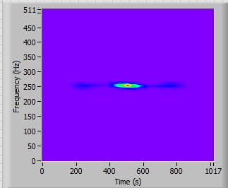
I m trying to figure out how to get the similarity of the two audio signals in LabVIEW.
I read the original signal of WAV file and do some operations with it (filtering etc.). After that, I want to know similarity of the signal (spectrogram) original and filtered.
I don't know about two things: distance correlation and cepstrum (Don t know how to implement).
I tried the file CrossCorrelation.vi of LabVIEW to compare my spectrograms of two signals, but I m do not know how to evaluate the result (check photo).
I get some sort of graphic information, but how can I assess it statistically? For example: output is similar to the entrance of 80%...
Can you show me any direction or advice?
I have LabVIEW 2013
I have also attached my VI + WAV signal source.
Commenting on the spectrograms is probably a good start.
If you are able to define the characteristics that are important, later, then go back and try to implement those measures.
I think that the Hilbert transform can be used to get an envelope. I did not and am unsure of the theory, but some research can give you some ideas.
Lynn
-
Regular CPU spikes every 15 seconds with USB 2.0 audio, fix, but refuses to install.
When streaming audio via the audio interface USB 2.0 Audio Class Compliant on Windows 7 Professional 64 bit update, there's regular CPU usage spikes up to 100% every 15 seconds, sometimes amounting to audio dropouts. Utility LatencyMon v6.5 reports that huge amount of CPU time is spent inside the usbport.sys driver whenever there are any audio stream of isochronous USB happening. I know that there is a supposed to be available to target exactly this problem - https://support.microsoft.com/en-us/kb/981214 fix - but the fix refuses to install, probably because the fix itself is quite old and does not seem to recognize the latest versions of the drivers usb*.sys on any instance to date of Windows 7.
I have tested and confirmed this problem on two different mobile-class workstation laptops from different manufacturers, both based on Intel 7 series / C216 QM77 chipset (Panther Point) and using the integrated chipset USB host controllers to connect to the audio interface (a 18i20 of Focusrite Scarlett). One of the laptops has EHCI and controllers xHCI routed to different physical ports, the other laptop has all the physical ports connected to xHCI; It might be interesting to note that the problem seems identical to the audio interface is connected to EHCI or xHCI. All other possible causes that usbport.sys were eliminated by a careful configuration and the measure, i.e. There is no limitation, no turbo CPU, no CPU C-State, not of processor HyperThreading, no food, no virtual memory paging management event, not even any SMI (System Management interrupt) passes, everything boils down to usbport.sys hogging the CPU.
It would also be interesting to note that according to Intel, there are a bunch of bugs known to host USB controller Series 7 / C216 chipsets, one can find an Errata section detailed from page 15 of the document Spec update - http://www.intel.com/content/dam/www/public/us/en/documents/specification-updates/7-series-chipset-pch-spec-update.pdf
Could this problem hogging CPU actually come from bugs in the hardware host controller USB drive operating system driver nuts? Or it comes from a bug unrelated in the OS driver? And what happened to the existing of the fix, why he refuses to install the operating system to date and how is the same old problem suddenly reappeared on automatically updating Windows 7 systems?
It is in any event, that my most sincere and humblest hold like a paying customer for a hotfix update fix this if possible, one that is truly committed to settle. Without corrective work, Windows 7 machines are quite useless for all serious audio work. I also feel that I speak not only for me but for all members of the global computer audio community who are trying to use Windows 7 with audio USB.
Just upgraded my Windows 7 Professional for Windows 10 Pro and the issue hogging CPU is now gone - no pics no CPU more, more dropouts no audio USB. (It would still be nice to have a fix for Windows 7 someday, too)
-
There is no audio signal of chronology in PREL12 the .m2ts files
Windows 7-64, first 12 items (64 and 32 - the same result)
Panasonic SC - 920 X camcorder, recoding format 1920x50p + DD5.1
1. If I just copy the files .mts from an SD card into the PC and import it into PREL then there no problem with audio. It is to play the preview and timeline window.
But in this case, I have a problem with the long record - camcorder breaks large files.
So I use the SD instead of the simple copy import.
2. the import of the SD using PREL12 (Get media of-> cameras Flip, AVCHD,...). In this case I get at disk .mts files and no audio timeline with these files. But in all other programs, these files are played with audio.
3. import the SD using Panasonic HDWriter program. In this case, I get .m2ts files (and some metadata files.). These files read normally (with audio) in any player and the program I have (WMP, MPC, Corel Video Studio Pro X 6 etc.). Except the chronology of the PREL12.
There is no audio signal of PREL timeline. And at the same time there is audio of the preview in the same PREL window (after double clicking on the item in the active project)!
There is no yellow bar above these clips. Project settings - 1980x50p PAL AVCHD
How to get audio of time?
dik07
Something for you to try.
The quick and very rough to solve this way...
Expert workspace...
Before you import your media into the project, set the predefined project manually to
PAL
AVCHD
Full HD 1080i25 5.1 channels
To manually set the project preset
- Open the project in the workspace Expert and go to file menu/new project and change the settings.
- In the settings, set the project preset to match the properties of the source media. OK to get out of there.
- In the dialog box new project opens, rename the project and make sure you have a checkmark next to the "Force selected setting on this project." OK to get out of there.
And then import your source files in the project by the different ways you have tried and found not to work for your application.
If it works, then the real solution...
Premiere Elements does not come with a preset project to PAL AVCHD AVCHD 1080 p 50 5.1 channels.
But, you can create one for use if gross suggests you need a project that is pre-configured with 5.1 channels included in its description. Please see details
Let know us the results and then we can decide what then.
Thank you.
RTA
-
No audio signal through HDMI (dv9700t CTO)
HP Pavilion dv9700t CTO Entertainment Notebook PC / Windows Vista 64-bit
I put the audio device by default for the device "Realtek Digital Output. I have no sound.
I've updated the audio drivers on the HP support site. Still no sound via HDMI. (the microphone quality was reduced at the point of being worthless)
I have updated the drivers with drivers from the site Web of Realtek. Still no sound via HDMI. (I found micro feature)
The box of bolt that I'm trying to connect to indicates that there is no audio signal passed him from this source (my laptop). I even tried to connect directly to the tv. Which doesn't work anymore.
Its almost as if there was no link between the audio and HDMI port.
 Message edited by Slybo on 12/23/2008 06:22Message edited by Slybo on 12/23/2008 06:24
I have dv9758ca and I have the same problem. No sound with the yamaha receiver. I sound with my LG TV and I tried with an Onkiyo recevier and it worked.
Once I had the sound on the yamaha (was a flook). the image was running on the TV and the screen of the computer (which is not normal) at the same time. then I concluded that the problem is the HDCP protection. the yamaha recevier is HDCP.
I've still did not know what the solution is, I just wanted to share my experience
-
Toshiba 32TL933G: No Audio signal in PC mode
Hello
I connected my laptop VGA to entry-level PC TV and the Audio output of the laptop to TV Audio IN.
No Audio in PC-Modus!Is it possible to go from Audio IN to the PC Input?
Now I have a video in PC * GOLD * Sound in EXT2, not together.
IF not, I will return itNevertheless a beautiful Asian.
RudolfThe fact is that VGA port does not provide the audio but video signal only.
So if you a TV connected to the computer laptop s port VGA, audio signal would not be provided.
You need connect the TV with an extra audio cable in order to get the sound.The laptop must be connected to the TV s L R taken audio using an audio cable additional of Y. So that you can connect to s portable headphone plug to two L R audio ports that are available on the back of TV s
-
fiber optical sensor su19 110 115 a 126 vs nor usb 6008
Hi expert... I am looking for idea or help on my project. I try to get the measure of mention nor USB 6008 sensor output. In fact, I'm new with nor peripheral usb n still study n the search on internet or n. forums I found an idea to connect the sensor by aoi, but I can't seem to get a measurement any. Is the sensor can connect directly to the device usb or need some custom wire diagram between them. Thanks in advance
First of all, it is useful if you name the manufacturer of the sensor. A single part number means nothing to most of us. You use the sensor fiber-optic Pepperl + Fuchs? Even better is to display the technical/manual plug of the sensor or links to them.
The data sheet that I found for the sensor to Pepperl + Fuchs is not very well written, in my opinion. It seems that the outputs are impulses with dependent amplitudes of the voltage and the frequency or the timetable set by the mode of operation.
If it's the device you use, the only way you have any possibility to decode the outputs with the USB-6008 box is to measure with an analog input and then process the data in the software. According to the supply voltage, you will probably need a voltage divider to reduce the output voltage of the sensor to a level compatible with the DAQ hardware. You also won't be able to use the high speed of the probe because the heart rate exceeds the Nyquist limit. In standard mode, you mighte be OK, but you can use a single channel of the USB-6008 to stay in the Nyquist limit.
Lynn
-
NOR-USB-8451 fails after spending a lot of time
Hello, I use a NOR-USB-8451 contact a panel using SPI (8451 scripting). NOR-USB is master and slaves are all (EEPROM, ADC and DAC) ICs on the Board of Directors. If I run my ATP in a loop of 10 times the 8451 will fail at the same point on the 8th time the test is run. When the problem occurs all SPI tests after this point will fail and the test of the 9th and 10th runs fails entirely SPI. If I remove the USB cable connected to the 8451 and re-connect it works properly again. If I run my loop it will fail again at the same point. It seems to me that there is a kind of problem of overflow here. I tried to add a Script Reset before all the build scripts, but it doesn't seem to work. I use CVI 8.1 to create the DLL referenced by TestStand 4.0.
Any help will be appreciated.
Nazar
JGB Consulting, Inc.
As it turns out, it's a mistake to programming on my part and not a problem with the device OR-USB-8451. I was building scripts of SPI with CVI, two of my scripts did not contain a CloseDevice call. This is what caused the error. Fixed all the CloseDevice to these scripts added.
-
Converts the audio signals of the mydaq in discrete values
Hi guys!
I'm currently building a project that accepts mydaq audio signals. I wanted to analog signals it have descrete peak values. Is this possible? I intend to use the discrete peak values and sum their place by using a registry change instead of the peaks. I think it is easier.
Any suggestions would be helpful. Thank you very much!
"".. "in the end we all hopes"...
FalseHope wrote:
Yes it detects peaks. but I can't use the peaks detected for something else. He's right there showing me the summits. But I wanted to use these pics for something else, and then to summarize. If there is anything I can do in the peaks detected so that I can use it and summarize, please tell me.
Yes, the Ridge detector shows you where are the tops. Now use a loop FOR autoindex on where are the tops for the level in those places. Now you have a table to the top. You can then use add table items to add them together.
-
uninstall the USB 2.0 by youyan acquisition card
I have vista 64.I cannot uninstall the EasyCap USB 2.0 capture card. I go to the control panel and click on uninstall, comes when I do setup.exe does not. My cd burner and dvd also quit when I installed it. (EasyCap USB 2.0 by Youyan acquisition card.
Hello
Try this free Revo program to remove it.
http://www.revouninstaller.com/revo_uninstaller_free_download.html
See you soon.
Maybe you are looking for
-
Satellite Pro A200: Card reader does not work after installing XP
Hello... I deleted Windows Vista from my Satellite Pro A200 for XP Home.I'm much happier with the machine now, but I am unable to get any response from the card reader. There is no mention in the manual supplied with the machine.I cannot find any ref
-
How to stop all these web pages trying to load?
My daughter and on 18 web pages signs trying to load, how can you stop that
-
Any ideas? Thank you Frank
-
error is seen getting restarts unexpectedly.
Original title: on installing windows 7 I made a huge mistake in fact I had a few malware in my 10 windows, and they keep coming after their scanning so I thought to remove windows 10 and reinstalling windows 7, but now I m not able to install window
-
BlackBerry Smartphones blackBerry services
I am a frustrated user of BlackBerry Storm 2 9550. I bought the phone in the United States in 2008 and when I tried to use the Services of BB to the Kenya could not connect. The phone was carrier Verizon but unlocked. I was able to use the other feat