How to acquire the generated signal?
Ladies and gentlemen, I am a novice in LabVIEW even if I practice solving problems more or less difficult, I got NOR cDAQ-9178, possess an entrance connected with output channels and after a plan of work on the signal acquisition and production separately, I decided that I could successfully combine the two plans and get the system of acquisition of generators. Hell I didn't know it wouldn't work. There are probably many things im doing wrong in this case, so no finance or support directly with the .vi is attached to the message would be so appreciated. Thank you.
One thing I think is that your generated frequency is not suitable with #S and Fs you have configured. Try #S = 10 k and Fs = 100 k.
Tags: NI Hardware
Similar Questions
-
How to acquire the catalogue of convenience store to operate ms fix?
Original title: attach it to microsoft
How to acquire the catalogue of troubleshooting I need to exploit the ms program fix
Hello
1. what Microsoft Fixit you trying to use?
2. what convenience store catalog are you referring?
If you are having problems using Microsoft Fix it tools, I suggest you to send your request in the Microsoft Fixit forums for assistance.
Let us know if you need help with Windows related issues. We will be happy to help you.
-
How to acquire the signal to very high sampling frequency
Hello world
My name is Luke Ho. I am trying to acquire the signal with Labview (Sthelescope). The signal comes from sensor acoustics, then filters and amplifiers to adapt to ADC rank (0 - 5V). Thus, the maximum frequency of the signal is 40 kHz.
According to the Nyquist theorem, I sampled at least 80 Khz signal.
Is there a sampling frequency devices like that? or y at - it another way of better? I used the Arduino before, but it was about 10 kHz.
I need your advice.
Thank you all and have a nice day.holucbme wrote:
Thanks for your recommendation
But is it possible without USB Data Acquisition, it is quite expensive for me.
This is the cheapest option to NEITHER. I tried to look for options to other companies, but more I found in the same price range, or not answering is not your condition of sample rate.
-
Hello.
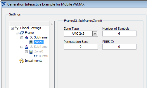
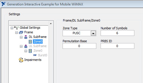
I use a VST OR to generate the WiMAX signal. I installed NO measure costume for Mobile/Fixed WiMAX 1.0 on the calculation. But I can't find any option on the front panel of the combination of the generation to enable AMC or PUSC for generated signal. This feature exist at all?
Thank you.
Hello sam2013ni,
That's all I see for AMC and PUSC. Look in "box Type".
Best regards
-
How to see the generated sql code
Hello
With the help of obiee 10g, I would like to see the generated sql code.
I logged in as administrator
Following manage-> sessions-> view log
But when I click on connect gives this error ii do me "no logs found.
The RPD administrator is a user with the recording as a 2 level.
Thank youBI_ORACLE_HOME/server/log/nqquery.log
to learn more:
http://gerardnico.com/wiki/dat/OBIEE/nqquery.log
Another method
http://varanasisaichand.blogspot.com/2010/04/how-to-set-logging-level-for-users-in.html
Thank you
Deva
Published by: Devarasu on December 6, 2011 17:26
-
How to acquire the values of CFP 1800 use FP read via RS 232?
Hello
We have an application in which there is a provision of the redundancy of the system. By redundancy, I want to say that I have a CFP-2120 and a host PC. Both are accquiring real-time AI module using concept shared Variable values. Each of these variables is linked with a particular channel of the Module & will acquire the data automatically. Initially when the system is Ok, the PC acquires data from the PSC 1800 using ethernet. Now, suppose that the ethernet connection has been lost, now that the PC will not be able to acquire. At this point, I want my PC to acquire data from the PSC 1800 using RS 232. In this case the binding of the variable with channel won't be of such use. I think that in this case, what I can do is to accquire data .vi FP READ and update the variable by plugging the variable for each channel.
What else will be the solution. Can someone tell me if my colleague and I are on the right track or if the best solution is here, please share with us.
The move will be highly appreciated.
Thank you best regards &,.
Samriddh Sarbalhi
Hello
You're going in the right direction for creating redundancy for you system controller PSC.
Here is the link for system redundancy with two components:
http://zone.NI.com/DevZone/CDA/EPD/p/ID/5997
I hope that this should help.
Anuj Bhansali
AE
NEITHER the India
-
How to connect the generator of signals of Agilent N9310A chauffeur?
Hello
I have a N9310A of Agilent connected via USB to a system using Labview 8.2 and the Agilent driver. The system goes into remote mode, so there is a communication. I tried to change the example of "Agilent N9310A RF Output" to exit BF (low frequencies) so that I can check the control of the signal using an oscilloscope gererator. I get the following error: Hex 0xBFFF0015 timeout expired before the operation is complete.
I must then disconnect and reconnect the USB cable that the example can not find the device. What happens here?
I'm new to using Labview with tools
-Thanks for any help
-Matt
Thanks for your help guys. The problem ended up being with the firmware of my Agilent N9310A signal generator. I got the A.02.03 firmware version and an upgrade to the current version (A.02.05) fixed something called an unstable connection between the PC and the N9310A.
This works.
-Matt
-
Unable to connect to the generator signal with LabView
Hello
I use a Tektronix AFG 3021 B signal generator. I installed the National Instruments driver (tkafg3k) for this device. My computer is connected to the signal in the block diagram generator, I place a block called "Example - Getting Started vi". I run the vi (there is no need of connections, so the vi has just the one block).
The vi then gives me this error:
Error 1073807343 has occurred to be initialized with Options.vi of tkafg3k
Possible reasons:
Driver status: (Hex 0xBFFF0011) primary error: error (Hex 0xBFFF0011) - information on the inadequate location or a resource that is not present in the system
I know that the signal generator properly communicating with the computer because when I run "VISA Resource Manager", I can ask for the name of the device and it returns the correct name.
-I'm using Labview 8.6.
-I have NI-VISA installed 4.2
-The driver that I use is available here: http://sine.ni.com/apps/utf8/niid_web_display.download_page?p_id_guid=005994E37F5B2318E0440003BA7CCD...
-J' use the driver that is for version 7.1
-J' uses this compliance record: http://joule.ni.com/nidu/cds/view/p/id/1095/lang/en
What is the cause of this error and how can I solve this problem?
Thank you.
-Zach
Do you really need to use the IVI driver, or you can use the LabVIEW driver? If you have need of IVI, configure you the Max with a logical name, etc.
PS You have posted to the wrong Board. It is for the signal generators of NOR. You should have posted to the Instrument of narcotics control.
-
How to convert the pulse signal line single layer
Hello
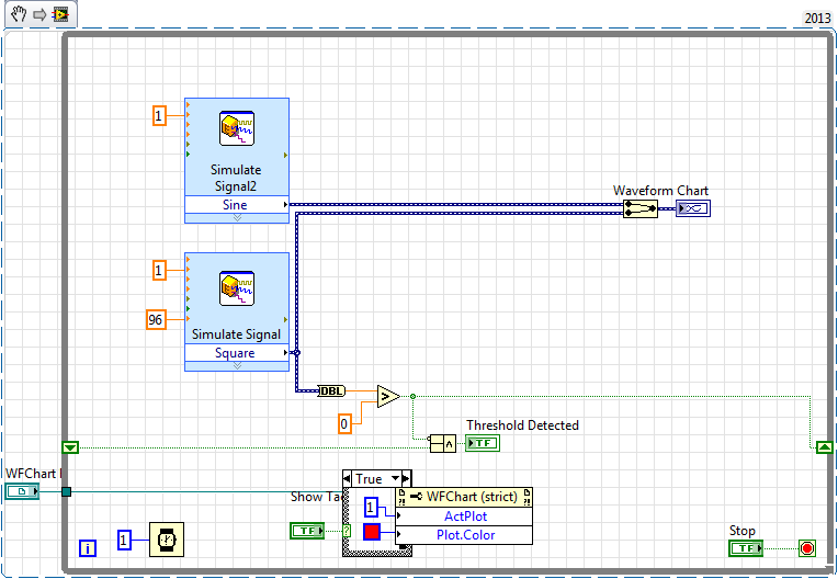
I tried to create a VI that will allow me to convert a pulse signal (generated by a tachometer) in a line single layer, indicating that a revolution succeeded. I would like to overlay this line on other signals generated.
I am able to detect the falling edge of the signal, but I could not make a suitable line. I tried to create a new waveform, and juggle the markers, but no method worked for me.
Does anyone have ideas for a good way to do this?
Below is my test VI.
Make the second vertical lines style trace (trace style: no points, no interpolation, fill - inf). a NaN whener you don't want a power cable and a '+ inf' when you want a vertical line.
Here's a simple example:

-
How to remove the generated output MFL end delimiter
Hello
The last delimiter value of ^ C is generated for some reason strange, as shown below:
16428281 ^ CFPL ^ C909709 ^ CFPL ^ C ^ C946971 ^ Phase fixed (1) ^ C67039703702 ^ CB ^ CConstructed ^ C17602 N 118 TR ^ C120/240 ^ C08561 ^ CN/A ^ C ^ C ^ C ^ C ^ C ^ C ^ C ^ C ^ C ^ C ^ C ^ C ^ C ^ C ^ C ^ C ^ C ^ C ^ C ^ C ^ CConstru
CTED ^ CAerial ^ C457225 ^ CUnknown ^ C ^ ONC ^ temperature closed ^ CClamp ^ CB ^ C1 ^ C2-cover ^ C296688734 ^ ONC ^ ONC ^ C50 ^ C ^ CYes ^ ONC ^ CYes ^ C22860Y/13200 ^ C ^ C ^ C ^ C ^ C ^ C ^ C ^ C ^ C ^ C ^ C ^ C ^ C ^ C ^ C ^ C ^ C ^ C ^ C ^ C ^ C
^ C ^ C ^ C ^ C ^ C ^ C ^ C ^ C ^ C ^ C ^ C ^ C ^ C ^ C ^ C ^ C ^ C ^ C ^ C ^ C16428199 ^ Coh_fuse_switch ^ C67039823007W ^ c-4 ^ CD15A2 ^ CAG0484 ^ C22.9 ^ C66637544501 ^ C8147503 ^ wrong ^ C4 ^ CJupiter ^ C45 ^ C0 ^ Cdefault ^ CYes^ C
Anyone know how to remove a delimiter of the end that is generated as part of an MFL exit or update my MFL to produce not the delimiter for the last value value?
Thank you
Yusuf
Hello
I could solve this problem with some java code that performed a few encode/decode base64 data (data MFL which was provided in the java legend turns out be an array of data bytes). After the decoding of the data I performed the following:
-find the length of the string
-If the string ends with the special charater, which in my case was "\x03".
-concatenated to the string with the version of the system to a new value of line.
Thank you
Yusuf
-
Could someone tell me how to convert the digital signals in table 1 d of digital waveforms
I use 9474 for drving an engine. for that I have uses 2 ports - to activate and another for running. These signals in the form of Boolean values. I am to convert these signals to a table and since iam doing a digital waveform. but when iam connecting these to the module 9474, it show an error "source is a digital waveform and sink is 1-d array of digital waveform... any body can help in these issueee please...»
Pop - up on the thread and choose Insert...
Build the table.
Ben
-
How to acquire the installation of Windows 8 media
I tried openSUSE dualboot with windows 8 on my laptop that somehow leads to a problem starting. To solve the problem, I had to do a clean installation of windows that wiped out all the data and hard drive partitions.
Now, the only problem is that I have a non activated Windows version 8 I can't activate.
Since I bought the laptop with windows preinstalled, which means also, I paid for the windows serial key (license) and I don't see why I should split up $ 200 to get a license that I already own.
I know that the warranty does not software but I also know that the manufacturer can provide the windows installation media for free or for a fee (since I already own it) on demand, so my question is: How can I make a request for the installation media, at what price, if any, and how he harvest?
HP ProBook 4540 s C9K69UT #ABA
8 Windows preinstalled
Country - Kenya
Active warranty until may 2014Hello:
You will need to contact HP Africa assistance on the link below.
Call the phone number for professional laptops which I suppose for the Kenya would be 234 1 27 11 999 or + 27 21 427 3240.
http://WWW8.HP.com/emea_africa/en/contact-HP/phone-assist.html
Inform the representative of customer services that you need a set of recovery discs for your laptop professional and you will need to provide the model # and # of series.
-
How to get the callUpdated signal and respond to the function of oncallUpdated slot?
Hello world:
I want to get the 'phone. callUpdated (const bb::system:
 : call & appeal) "signal and do something in the slot to onCallUpdated function, but the problem is crack onCallUpdated() function does NOT respond!
Here is my code:
. CPP
#include
MyApp (bb::cascades:Application * app) in myApp.cpp
bb::system::phone::Phone phone; bool success = QObject::connect(&phone,SIGNAL(callUpdated(const bb::system::phone::Call&)),this,SLOT(onCallUpdated(const bb::system::phone::Call&))); qDebug()<<"bb::system::phone::Phone phone: "<When the application runs, the success of back connect is true!
void Quicker::onCallUpdated(const bb::system::phone::Call &call) { //CallState::Type state = call.callState(); qDebug()<<"onCallUpdated is called"; }In myApp.hpp
#include
void onCallUpdated(const bb::system::phone::Call &call); In the bar - descriptor.xml
run_when_backgrounded access_phone I found the problem:
bb::system::phone::Phone phone;
the code must be in the *.hpp.
Thank you all.
-
How to acquire the data of hp34970a using labview
Hello
I'm new to LABVIEW. I saw an example of vi on agilent 34970 ez scan. Can I add or make changes to State example to run my vi? When I run the example of the instrument, it's stopping and takin juz one analysis. Wat shud I do to run it for a while? where shud I make the changes to the trigger and scanning?
can someone help me?
Yes, if you have no loop, the code runs only once. Have you looked at the example in the thread, I gave?
You can take the tutorials.
-
How to display the generated Dispdiag utility DAT file?
I have collected dispdiag dat file utility. I am unable to view the file using notepad normal edit. is there any utility or the command to display the data on the formatted way dat file. Thanks in advance :)
Dispdiag d produces a dmp file which can be read with WinDbg and/or BlueScreenView
The .dat file is partially visible in Notepad
Maybe you are looking for
-
The status bar is missing after upgrade to 4 beta 4 beta 7 6.
This old thread from blocking The status bar at the bottom of the window was visible when I was using Beta 6, but after upgrading to Beta 7 is missing. I restarted Firefox many times.
-
error message Airport base station agent quit unexpectedly
My WiFi is erratic and the above message appears. Anyone know what is happening? I have reset my airport extreme, but this did not help.
-
How to install the new HDD on Satellite M70?
Hi, I have a Satellite M70 PSM75E, I want to move a hard drive of 250 GB, can give me instructions how to install and what type of disk HARD inface do I go?Your help is appreciated
-
Satellite A500-1DN - crashing everything by playing games
Hi all About 2 months ago, my friend bought a Toshiba satellite A500-1DN. After about 2 weeks, she decided to put 2 games on it (guildwars and jedi knight academy). We quickly realized that after about 1 hour of playing, the computer would crash to a
-
Incompatible print cartridge error C309g.
Incompatible print cartridge error C309g. When replacing foul 564 XL (black), now I get this message. The new cartridge works in another printer that uses 564 XL. Went ahead and tried another brand new 564 XL - same message. Have turned printer on an