SMU-6363 pressure measurements
Hi guys,.
First post here. I tried to search first for documentation but empty is come.
I use the analog inputs on the 6363 map to make some measurements of voltage. I have 2 questions:
- I know that the channels are limited to +/-10 volts for entries. I have a 25 Volt with a resistance line series regular (50mOhm) sense. I want to do a differential measure resistance across with 2 analog channels. The real tension between the two points will be in the range of mV, but the unique finished voltageon each will be ~ 25 V. Will this work?
- In a similar configuration, but on a 5 volt line can I build a differential measure through a resistance of sense current using 2 channels and then turn around and use one of these same channels for a single measure is complete wrt gnd?
Thanks for your help!
There is a row in the datasheet that States
|
Maximum voltage of work for the analog inputs (signal + common mode) |
±11 AI GND v |
So with a 25V common-mode voltage, you will hurt your card. The 5V line should be fine.
If you look at Digikey, there are chips specially designed to detect a current shunt. The differential voltage amplifiers will become a simple nerve from the ground.
Tags: NI Hardware
Similar Questions
-
I don't get the desired pulse a counter in an SMU-6363 on every nth in pulse.
I am in a position certain characteristics of the impulses of the encoder. I need to generate a pulse ON this about-face with every pulse of the nth encoder in.
This impulse generated will be used to trigger measures andcounter analog acquisition on other counters in the SMU-6363.
I have attached my code. I expect to have a pulse on the same length of high and low.
This is not the case. What I'm doing wrong here? I use SMU-6363.
Magyar salvation,
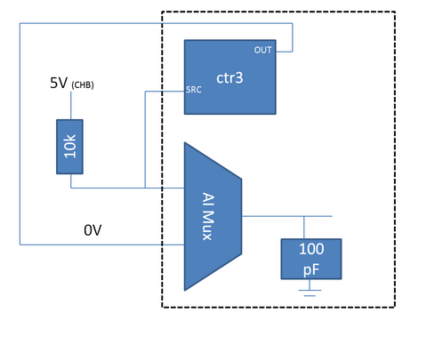
It is not a voltage divider (the 6363 input impedance is > 10 GOhm), but rather what we call 'ghosts' where high source impedance increases the time of the multiplexer and causes channels to affect another. The behavior you reported in your other post has the same cause.
I think that the same behavior is at the origin of many of the dupilcate to be registered where the output of the ctr is 0V and the output of the encoder is 5V (or perhaps transiiton of 0 to 5V). When the MUX switches to 0V on the 5V channel, it takes time to charge the capacitor 100 pF on the ADC. The amount of time it takes is relatively high due to the resistance of 10kOhm (on your encoder) that the capacitor will charge through. Meanwhile, the line (as evidenced by the counter input source) is obviously drawn below the TTL and causing a double edge to be registered.
Digital filtering still may not be a bad idea, even with the encoder active drive as source counter line is always connected to the entrance of a multiplexer - when there is no doubt that I generally include it for good measure.
Best regards
-
How to handle interruptions in SMU-6363
Hello
I'm working on a PXI tester to test the ASICs. I use in the tester, SMU-6363 map and module SPI NI USB-8452 to speak to ASIC chips. The ASIC chip sends a signal of interruption to the SMU-6363 when its finished with a certain measure, for example. a measure of tension of ADC. On receipt of this signal of interruption of the ASIC, the tester PXI running LabVIEW must obtain measured value through SPI (NI 8452) to ASIC.
I have the following questions regarding this set upward:
1. can I connect the signal interruption of ASIC to any PFI on SMU-6363 line so that in case of the impulse of the interruption, the tester can meet this interruption by launching SPI Comm by nor-8452 module?
2. If so, how can I make a coding in LabVIEW to meet this impulse interruption PFI online?
Thank you
Jeet
Hi Jeet,
You see error-201062? By changing the default value of detection tasks are buffered, and it is only supported by port 0. To make it work on all ports on your device in the X series, you'll want to add an entry DAQmx Configure Buffer.vi and explicitly set the size of the buffer to zero. I have re-attached my VI example with this change.
Hope that helps,
Dan
-
How to trigger SMU - 6363 AI with the PXI-4142
Hello
SMU-1082
SMU-6363
SMU-4142
LabVIEW 2012 SP1
Hello
I'm trying to trigger action (SMU-6363) analog input with my SMU (SMU-4142). The API OR-DCPower has a VI called VI of Signal to export, that I could use to export the trigger signal in a specific line when 'Complete the event Source' comes up on my EMS.
The problem now is that i ' v tried several lines to transfer the signal to the SMU-6363, but unfortunately I still have an error of DAQmx. Has anyone tried similar before sync? Which internal lines I have to use to get this working? I'm just not producing a moment of tension at the time that the EMS (Single, Point). After SMU has defined the level it must send the trigger for SMU-6363 who would then measure the external signals constantly.
Thanks in advance!
-henkkaHello
I solved the problem of routing measure relaxation of SMU with Signal.vi export online PFI0 of SMU-6363 (SMU 3 channel). Then I started every other SMU channels (0:2) with this signal to trigger by using the configuration digital edge measure Trigger.vi (the VI input terminal is PFI0).
I configured the data acquisition sample clock to use the PFI0 as a source of the clock. With this method I am able to measure sinus 2 kHz generated with four channels EMS individually with my DAQ without no phase shift (0.1 degrees) between own EMS measurement and data acquisition.
Hope this helps anyone with the same kind of problem.
Best regards
-Henry
-
Dear community,
I am trying to implement a background basket (software) PXI trigger on a chassis NI SMU-1082 with LabView 2015 (32-bit) running on an SMU-8135:
HS-DIO (SMU-6544) in slot 2,
-Acquisition of data (SMU-6363) into the Groove 4,
-Flex RIO (SMU-7962R + OR-6583) in the Groove 3.
The trigger schema is explained in the attached file ' LV-PXItrig-HSDIO-DAQ - overview.jpg ".
Scenario 1: written DAQ analog signal and sends signals trigger HS-DIO (software) through bottom of basket, after East of waveform of the complete signals to DAQ for acquisition.
Scenario 2: logical impulse on an external port HS-DIO triggers signals HS-DIO, after HS-DIO waveform is complete DAQ triggered for the acquisition of the ADC by the backplane.
In principle this breaks down to send a trigger of module A to B by PXI backplane. The SMU-1082 chassis has a bus trip with 8 lines (PXI_trigX, X = 0,..., 7) more a trigger in Star controlled the slot 2.
I've linked to implement a software trigger, but I can't access the refreshing resource and execution, see the attachment. Other ways of implementation including the DAQmx Terminal / routine disconnect Terminal have not worked for me either. I am aware about the connection of trigger using the node property VISA but I can't make a trigger.
Tips, comments or solutions are appreciated. Thank you!
For scenario 1, you want to trigger the HSDIO acquisition to begin as soon as the analog output DAQ starts? You can use
DAQmx Export Signalto send the trigger for the start of one of the lines from the Trig PXI backplane. Then, you need to configure your HSDIO acquisition to use a trigger digital beginning on the same line of trigger. Take a look at the example of the "Dynamic hardware generation start trigger" in the Finder of the example (help > find examples)For scenario 2, looks like you do a dynamic unit HSDIO generation when a digital trigger arrives on one of the PFI lines. Once the build is complete, you want to send a trigger for the DAQ hardware to begin sampling. If this is the case, you again use a trigger to start material in your task of NOR-HSDIO, as you did for scenario 1, but use external trig line as the source, rather than the bottom of basket. There is no case of material when the build is finished, but you can use a marker in script mode event instead. The example of the Generation with dynamic event marker' in the example Finder gives a good starting point for this type of operation. You'll want to set the output terminal for the event to be a line of backplane trig, and then tap the DAQmx to start on the same line trig trigger.
-
How to count the number of edges using counters SMU-6363
Hello
I'm counting the number of edges in a test signal in a duration of 50 Ms I use the SMU-6363 map and connect to the TRC test signals 0 SRC (PFI 8). Is that a correct connection? What else do I need hardware wise be a correct set for this application?
Thank you
Jeet
Hi Jeet,
This configuration is correct. Hardware wise, that's all you need to do.
Kind regards
Jorge Fernandez
Technical sales engineer
National Instruments
____________________________________________
Certified LabVIEW Associate Developer (CLAD) -
Hello
I must acquire Differential (8) and NRSE (16) of the analog inputs with an SMU-6363. I'm confused, what kind of configuration in the program labview is necessary to achieve usage OR daqmx live I enclose two modes of configuration of blockdiagrams that could match my need. Kindly help me which one is configured correctly
Thanks and greetings
Naveen
The background a type2 seems correct.
-
stop DC-source after awhile and then begin the pressure measurements
I don't think that what I want is so difficult, but I have very little experience with labview.
I generate a continuous voltage for a period of time. After the time of the source voltage must become zero and pressure measurements must begin.
In vi, I did the steps start at the right time, but the source never generates a voltage.
I placed a picture of the diagram as an attachment. There is nothing in the case if the value false.
The while loop ends after the time to reload, and then the case would become true.
The part related to PXI1Slot2 for the source and the part related to PXI1Slot3 for measurements. (But as I said, there is no problem with my measurements, the DC-source is my problem)
I know that I can use the source because I can do generate a voltage if I place the part related to PXISlot2 on its own to a vi.
Hello
Both sides in the case structure should arrive in a certain order? As they are it is unclear who will take place in what order. If they must be in order, use the wire of the error to force the order or try a sequence structure to put them in order in consecutive images.
-
Using SMU 6612 to measure PXI-6528 pulsewidth channel - channel is not available.
Hi all
I use SMU 6612 card counter to measure the pulse width of the signals to PXI 6528 DIO card. These two cards are in the same chassis PXI (NI-SMU-1065). I could measure the pulse widths using the example LabVIEW 2013 Counter - pulse width of reading and (over) frequency example of .vi. However not all channels of the PXI-6528 map appear in the drop-down list of channels on the pulse width can be measured. Try to connect any other channel that those which are available in the drop-down list returns the error. On the PXI card port 6528 0,1 and 2 are entered ports and port 3-5 are output ports. I can measure the pulse on port 0, 3 width and line 0 port 1 and 4.
Can someone explain to me why don't see port 1 or port 2 channels in the drop-down list or force the VI to measure the width of pulse on these channels?
I can plug PXI-6528 external input channels SMU 6612 counter input channels and measure the pulse width, but if possible I'd like to avoid the external wiring between the 2 cards.
Probably not. Unless the routing plan is in fact reversed as it seems a bit sorta that. As stated on my system, you can route * of * a port of entry * to * RTSI, or you can route * of * RTSI * to * one output port. This does not make much sense to me, but that's what I see:
If the routing card * is * reversed, your only likely workaround without physical wire would be to generate impulses in question of port 3. It's pretty clear that 1,2,4,5-tetrachlorobenzene ports have no ability to interact with the bus timing, physical wiring would be the only option.
-Kevin P
-
I have a pressure sensor that generates the current signal. I want to connect it to the module NI 9205 to collect the signal. I already have a NI 9944 resistance to
transfer from current to voltage signal. Could you tell me how to connect the transducer, resistance and the Module 9205?
-
the basis of my time scrolls not (in my blood pressure measurements)
I have a DC 5v pot connected to my USB DAQ 6008. In labVIEW when I run it I get my voltage output as expected but the time base does not scroll it remains fixed. When I change the axis scales the output voltage varies even in the first second only. Does anyone know what is the problem?
I don't think you can ignore the timestamp which is part of the dynamic data. I never use dynamic data and I hope that I am never placed in a situation where I have to.
Eventually, a difficulty for the elevator VI is in the attachment. Since you have wired some scalar indicators data, TI EÉ seems not you care about 1000 samples so I used a function average to get a scalar value at least a certain meaninig. Then I converted to a real scalar.
If you want to paste the dynamic data, you cannot use the function bundle in VI of the gear. The correct function would be the merge of the signals feature.
-
Measure the period and the peak value at crest of a sine wave
Hello
I am new to Veristand and Labview and I was wondering if there is the possibility to do the following:
I would like to measure the period of a sine wave that I capture from analog input of my data acquisition (SMU-6363). Apart from that, I also want to measure the value of crete to crete (Vpp) of the sine wave.
I hope you can help out me.
Thank you.
If the sine wave is of significantly higher frequency than the primary control loop can run... The best way to do it would be to put the DAQ hardware in waveform input mode and use a custom device to read the waveform and perform analyses.
an example is here: requires some labview skills
\examples\NI VeriStand\Custom analysis Devices\waveform -
E/s instrument with SMU-1062 q Assistant
Hello
I use a SMU-1062 q with LabVIEW 2009 installed on it. In Measurement & Automation Explorer, the frame is visible, as well as two cards SMU-6363, I built in. E even works without all the failures 6363 self-test.
My problem is, that after if I insert an Instrument of e/s Assistant in LabVIEW 1.01, then click on choose an instrument, the SMU - two 6363 do not appear in the list. Only Com1 and LTP1 is listed.
What should I do? Thank you very much for your support!
Best regards, Michael
The 6363 is programmed with DAQmx functions. You will use the DAQ Assistant.
-
I use the SMU 4140 to measure the curves of voltage/current for the transistors - it sets a voltage & I read (not necessarily on the same channel). But I noticed a peculiarity in the data according to the current limit.
First of all, I get different results if I let him autorange device compared to manually set the current limit.
In particular, there is a current lag that occurs for differnent current limits.
In the attached file, the current is allowed to Auto for the Red data and fixed at 100 Ma for data in blue. [the axes are current drain source - ID- & door - Source voltage VGS]
Any idea what is the origin of the offset .02mA in the Red data?
Thank you for following up with an explanation.
Looks like this resource to answer your question:
http://digital.NI.com/public.nsf/allkb/EE869FC813944EAC862578F0005519F5
-
RF Mux PXI-2546 driver stops working when DAQ SMU-6259 is used.
Hi, I am experiencing a very strange thing. I have a system with two 1065 equipped chassis with about 15 different instruments.
It was working fine and has done for several years. Today the SMU-6363 DAQ crashed, I tried to replace it with a spare DAQ SMU-6259. I started with switching just the daq spare in but then the computer crashed every time during the installation of the pilot SMU-6259. So I thought that I need a driver update and installed DAQmx 15.1 (previous version was 14.5). It has not made any change. Computer always crashes constantly. Finally I found that if I remove the PXI - 2546 Rfmux in the SMU-6259 DAQ system will install and work properly. But now Rfmux PXI-2546 will not work when acquiring data SMU-6259 are installed on the system. I can get the Rfmux to work if I take the DAQ and vice versa.
Why is it like this and what can I do to solve?
I do not understand why a PXI-2546 Rfmux and an SMU-6259 DAQ interfere with one another.
/ Erik
Hi Anton, thanks for your answer!
Yes, it's very strange. I narrowed down it to these two devices. I got the blue screen during the installation of the Windows driver. So I tried first update the driver OR DAQmx. Who did not have any change.
Then I tried to roll back the NOR-DAQmx driver to a previous version. Crashes stopped then, but I could not both devices to work simultaneously. In the windows Device Manager, he showed a problem for the NI DAQ PXI-2546 peripheral device. I don't know why a mux is considered DAQ hardware either. The description of the problem says "some free resources". If I could get the Rf mux to work if I unplugged the daq and vice versa.
For the last two days, I was reinstall the system from scratch. I'm not done yet because it takes so much time to do this, but it seems to be ok now. But what a pain. I started with just the driver Rf Mux (Switch).
To do this I had to download almost 3 GB! For a 2 x 4 x 1 Mux driver. Then, the driver for the installed switch some NOR-DAQmx which I had to then update and download even more.
I think that NEITHER makes it very complicated with the pilot stuff. Instead of having these huge drivers packages which supposed to cover everything, it would be better with the smaller specific device drivers that could be easily found on the web under each device.
In any case I hope it should work ok now. I wonder what will happen when I get home my repaired SMU-6363. Should I plug it in or simply do not bother because I could face the same problem again?
/ Erik
Maybe you are looking for
-
Viewfinder does not external registration
I upgraded to macOS Sierra immediately. It went well until suddenly Finder has not shown the HDS or the USBs external even though they do not appear in the utility disk and on my desk. How can this be addressed?
-
Hello, I got my iPhone 5s today, and I just noticed that my locking/unlocking button is loose, and I don't know if it's normal, that's why I'm asking here, and my home button also makes a very loud rattling noise, I don't know if this is not normal e
-
When you use Firefox 16.0.2 and browsing Facebook, the browser stops responding and an error message appears saying that the script has stopped working. (Script: chrome://wrc/content/overlay.js:1677))This only happens on Firefox and Facebook work wel
-
Install the network and specific peripheral controller on Tecra A8 PTA83E
Hello I have to install windows XP on Tecra A8 PT83E. Everything work fine except 2 devices. Indeed, in Device Manager, I can not install network controller and a device specific. Where can I find the two driver or which driver to install? All other
-
Drivers for transceiver eHome infrared?
I bought a hp Media Center Remote and receiver IR blaster. My Device Manager it is as "infrared transceiver eHome" but says it cannot locate the files for it. I contacted HP and they said that they did not provide the driver files it was included in