Analog input query SMU 6363
Hello
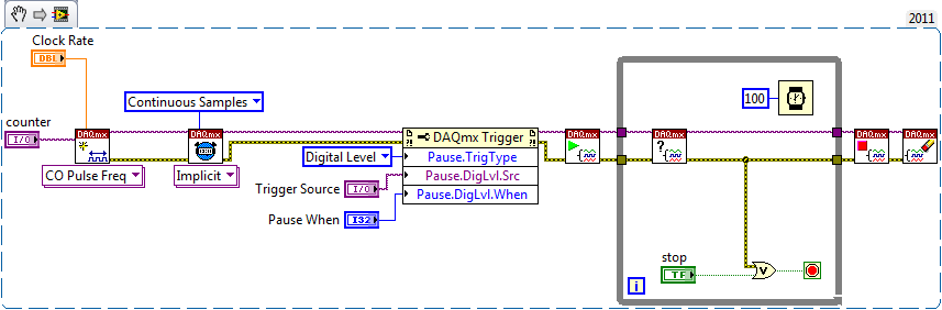
I must acquire Differential (8) and NRSE (16) of the analog inputs with an SMU-6363. I'm confused, what kind of configuration in the program labview is necessary to achieve usage OR daqmx live I enclose two modes of configuration of blockdiagrams that could match my need. Kindly help me which one is configured correctly
Thanks and greetings
Naveen
The background a type2 seems correct.
Tags: NI Hardware
Similar Questions
-
SMU-6363 pressure measurements
Hi guys,.
First post here. I tried to search first for documentation but empty is come.
I use the analog inputs on the 6363 map to make some measurements of voltage. I have 2 questions:
- I know that the channels are limited to +/-10 volts for entries. I have a 25 Volt with a resistance line series regular (50mOhm) sense. I want to do a differential measure resistance across with 2 analog channels. The real tension between the two points will be in the range of mV, but the unique finished voltageon each will be ~ 25 V. Will this work?
- In a similar configuration, but on a 5 volt line can I build a differential measure through a resistance of sense current using 2 channels and then turn around and use one of these same channels for a single measure is complete wrt gnd?
Thanks for your help!
There is a row in the datasheet that States
Maximum voltage of work for the analog inputs (signal + common mode)
±11 AI GND v So with a 25V common-mode voltage, you will hurt your card. The 5V line should be fine.
If you look at Digikey, there are chips specially designed to detect a current shunt. The differential voltage amplifiers will become a simple nerve from the ground.
-
Frequency measurement of analog input using DAQmx C APIs on SMU-6341 map
Hello
I use Linux DAQmx and attempt to measure the frequency of analog input using the map DAQ SMU-6341.
There is an ANSI-C frequency measurement example:
/ usr/local/natinst/nidaqmx/examples/ansi_c/Analog_In/Measure_Frequency/Cont_Freq-Int_Clk-SCXI1126
However, the call to DAQmxCreateAIFreqVoltageChan results in the following error:
DAQmx error: selected physical channel does not support the type of measure required by the virtual channel you create.
Create a channel to a type of measure that is supported by the physical channel, or select a physical channel that supports the type of measure.
Property: DAQmx_AI_MeasType
Required value: DAQmx_Val_Freq_Voltage
Possible values: DAQmx_Val_Current, DAQmx_Val_Resistance, DAQmx_Val_Strain_Gage, DAQmx_Val_Temp_BuiltInSensor, DAQmx_Val_Temp_RTD, DAQmx_Val_Temp_Thrmstr, DAQmx_Val_Temp_TC, DAQmx_Val_Voltage, DAQmx_Val_Voltage_CustomWithExcitationTask name: _unnamedTask<0>
State code:-200431
DAQmx does support the function of the frequency on the map 6341, or should we use examples of voltage and calculate the frequency manually?
Frequency of HAVE it is a type of channel that has been supported only on the SCXI module name of the example.
You will need to use a voltage input channel and calculate the frequency manually for your device.
-
Continually acquire analog input, internal clock, break, Multiple device
I have a PXI chassis with 6 cards SMU-6363. I want to acquire data on the channels of each SMU-6363 map continuous AI, using the internal clock for timing. I need to use a trigger to pause reading of a DI on one of the cards SMU-6363 for a break and to reactivate the acquisition. I came across this example: https://decibel.ni.com/content/docs/DOC-12256/ , but keep getting error-201019 DAQmx start task "trigger break is not supported in a task to more devices. To configure the start of break in a multi-device configuration, you must use no more than one device per task and route manually clock in demand signals. »
The problem is that the configuration of I is made during execution by the operator. Sometimes they want to acquire data on one HERE through all 6 cards SMU-6363, sometimes they want to acquire data on each channel of AI through all 6 cards SMU-6363. What makes the task definition until manually route clock signals between devices for each rather difficult task.
Is there a simpler way to solve this problem?
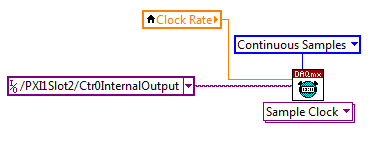
Set a task to output counter - something like this:
Next, configure your task of analog input to use the sample clock output of the meter:
Best regards
-
I don't get the desired pulse a counter in an SMU-6363 on every nth in pulse.
I am in a position certain characteristics of the impulses of the encoder. I need to generate a pulse ON this about-face with every pulse of the nth encoder in.
This impulse generated will be used to trigger measures andcounter analog acquisition on other counters in the SMU-6363.
I have attached my code. I expect to have a pulse on the same length of high and low.
This is not the case. What I'm doing wrong here? I use SMU-6363.
Magyar salvation,
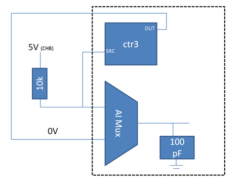
It is not a voltage divider (the 6363 input impedance is > 10 GOhm), but rather what we call 'ghosts' where high source impedance increases the time of the multiplexer and causes channels to affect another. The behavior you reported in your other post has the same cause.
I think that the same behavior is at the origin of many of the dupilcate to be registered where the output of the ctr is 0V and the output of the encoder is 5V (or perhaps transiiton of 0 to 5V). When the MUX switches to 0V on the 5V channel, it takes time to charge the capacitor 100 pF on the ADC. The amount of time it takes is relatively high due to the resistance of 10kOhm (on your encoder) that the capacitor will charge through. Meanwhile, the line (as evidenced by the counter input source) is obviously drawn below the TTL and causing a double edge to be registered.
Digital filtering still may not be a bad idea, even with the encoder active drive as source counter line is always connected to the entrance of a multiplexer - when there is no doubt that I generally include it for good measure.
Best regards
-
How to trigger SMU - 6363 AI with the PXI-4142
Hello
SMU-1082
SMU-6363
SMU-4142
LabVIEW 2012 SP1
Hello
I'm trying to trigger action (SMU-6363) analog input with my SMU (SMU-4142). The API OR-DCPower has a VI called VI of Signal to export, that I could use to export the trigger signal in a specific line when 'Complete the event Source' comes up on my EMS.
The problem now is that i ' v tried several lines to transfer the signal to the SMU-6363, but unfortunately I still have an error of DAQmx. Has anyone tried similar before sync? Which internal lines I have to use to get this working? I'm just not producing a moment of tension at the time that the EMS (Single, Point). After SMU has defined the level it must send the trigger for SMU-6363 who would then measure the external signals constantly.
Thanks in advance!
-henkkaHello
I solved the problem of routing measure relaxation of SMU with Signal.vi export online PFI0 of SMU-6363 (SMU 3 channel). Then I started every other SMU channels (0:2) with this signal to trigger by using the configuration digital edge measure Trigger.vi (the VI input terminal is PFI0).
I configured the data acquisition sample clock to use the PFI0 as a source of the clock. With this method I am able to measure sinus 2 kHz generated with four channels EMS individually with my DAQ without no phase shift (0.1 degrees) between own EMS measurement and data acquisition.
Hope this helps anyone with the same kind of problem.
Best regards
-Henry
-
Dear community,
I am trying to implement a background basket (software) PXI trigger on a chassis NI SMU-1082 with LabView 2015 (32-bit) running on an SMU-8135:
HS-DIO (SMU-6544) in slot 2,
-Acquisition of data (SMU-6363) into the Groove 4,
-Flex RIO (SMU-7962R + OR-6583) in the Groove 3.
The trigger schema is explained in the attached file ' LV-PXItrig-HSDIO-DAQ - overview.jpg ".
Scenario 1: written DAQ analog signal and sends signals trigger HS-DIO (software) through bottom of basket, after East of waveform of the complete signals to DAQ for acquisition.
Scenario 2: logical impulse on an external port HS-DIO triggers signals HS-DIO, after HS-DIO waveform is complete DAQ triggered for the acquisition of the ADC by the backplane.
In principle this breaks down to send a trigger of module A to B by PXI backplane. The SMU-1082 chassis has a bus trip with 8 lines (PXI_trigX, X = 0,..., 7) more a trigger in Star controlled the slot 2.
I've linked to implement a software trigger, but I can't access the refreshing resource and execution, see the attachment. Other ways of implementation including the DAQmx Terminal / routine disconnect Terminal have not worked for me either. I am aware about the connection of trigger using the node property VISA but I can't make a trigger.
Tips, comments or solutions are appreciated. Thank you!
For scenario 1, you want to trigger the HSDIO acquisition to begin as soon as the analog output DAQ starts? You can use
DAQmx Export Signalto send the trigger for the start of one of the lines from the Trig PXI backplane. Then, you need to configure your HSDIO acquisition to use a trigger digital beginning on the same line of trigger. Take a look at the example of the "Dynamic hardware generation start trigger" in the Finder of the example (help > find examples)For scenario 2, looks like you do a dynamic unit HSDIO generation when a digital trigger arrives on one of the PFI lines. Once the build is complete, you want to send a trigger for the DAQ hardware to begin sampling. If this is the case, you again use a trigger to start material in your task of NOR-HSDIO, as you did for scenario 1, but use external trig line as the source, rather than the bottom of basket. There is no case of material when the build is finished, but you can use a marker in script mode event instead. The example of the Generation with dynamic event marker' in the example Finder gives a good starting point for this type of operation. You'll want to set the output terminal for the event to be a line of backplane trig, and then tap the DAQmx to start on the same line trig trigger.
-
What is the minimum response of analog input, through DSP online, output analog time?
Hello experts!
I want to know if it is possible to get a very quick response latency (~ 1 ms) sound recording (analog input), through online registration (DSP online), the presentation of his (analog output) processing, by using the DAQmx programming codes. My system of NEITHER includes NOR SMU 8135, SMU 6358 DAQ Multifunction controller and SMU 5412 arbitrary signal generator. I also have access to the latest version of Labview (2015 Version) software.
My project is on auditory disturbances, which inovles record vocalizations, manipulating the recorded vocalziations and then present the manipulated vocalizations. My current idea of how to achieve this fact triggered output voltage after reading the input using DAQmx Read samples. DAQmx Read output is filtered online and then passed as input for the DAQmx writing for analog output. For purposes of illustration, examples of code are presented below. Note for simplisity, codes for the trigger part are not presented here. It's something to work in the future.
My question here is If the idea above should be reaching ~ 1ms delay? Or I have to rely on a totally different programming module, the FPGA? I am very new to Labview so as to NEITHER. After reading some documentation on FPGA, I realized that my current hardware is unable to do so because I do not have the FPGA signals processing equipment. Am I wrong?
Something might be important to mention, I'm tasting with network (approximately 16 microphones) microphones at very high sampling rate (250 kHz), which is technically very high speed. Natually, these records must be saved on hard drive. Here again, a single microphone is shown.
I have two concerns that my current approach could achieve my goal.
First, for the DAQmx Read function in step 2, I put the samples to be read as 1/10 of the sampling frequency. It's recommended by Labview and so necessary to avoid buffer overflow when a smaller number is used. However, my concern here associated with the latency of the answer is that it might already cause a delay of 100 ms response, i.e. the time to collect these samples before reading. Is this true?
Secondly, every interaction while the loop takes at least a few tens of milliseconds (~ 30 ms). He is originally a State 30 late?
Hey, I've never used or familiar with the hardware you have. So I can't help you there.
On the side of RT, again once I don't know about your hardware, but I used NOR myRIO 1900, where he has a personality of high specific speed for the RT where I can acquire the kHz Audio @44 and process data. Based image processing is ultimately do the treatment on a wide range of audio data you have gathered through high sampling frequency and number number of samples as permitted by latency, please check this .
I lost about 2 weeks to understand host-side does not work and another 2 weeks to understand the even side of RT does not work for online processing (real time). Then, finally now I'm working on FPGA, where the sampling rate is 250 kHz (of course shared by multiple channels).
The complex thing with FPGA is coding, please check if the filter you want is given below as labview automatically generates some codes of some filters.
Most of them will work in 1 SCTL IE if your target has 40 MHz clock algorithm will run in 25 ns. That's what I was looking for, I hope you

See you soon... !
-
[fpga] Configuration of analog input or 7965R
Hi all
I have a card FPGA NI FlexRIO (SMU-7965R) with an adaptation module (NI 5733). I'm using Labview real-time 2012. My measurements are dominated with harmonic sound of 60 Hz, which is most likely due to the ground loop. I try to put my analog inputs (as opposed to the CSR, NRSE) differnetial mode to try to overcome the ground loop. I came across this link which explains how to configure the FPGA input channels-
http://digital.NI.com/public.nsf/allkb/08EF26D2E9041BC6862570E0001E442E
However, the installation program of the RIO device for my goal of opening, I found that there is no option to choose the channel configuration (as shown in the attached picture). This means that the analog channels are in differential mode by default? If this is not the case, how can I change?
Any help will be greatly appreciated.
Hello!
This KB is in what regards R, not FlexRIO product line series materials. I know it's a little confusing because the 7965 has an indicator of 'R' at the end of the model name, but the R simply it is a product with an FPGA that is programmable by the user.
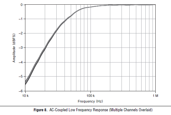
Unfortunately, the adaptation modules FlexRIO 573 x are all only ended then we will not be able to change to the differential. What is the frequency of the signal you're trying to measure? Another option would be to set the 5733 coupling AC mode, which would give the frequency response following, dramatically eliminating any sound below 10 kHz.
-
I am acquiring several channels of analog voltage input at the same time, I need to send an output analog two seconds after the start of the entry.
I'm running an experience with accelerometers on a query table.
I start the trigger and the table remains still for two seconds, which allows a reference level for all sensors.
Then the output signal of the VI removes the break in the motor controller.
The speed measured by the encoder is sent to one of the input channels.In this way, our accel and speed data are synchronized.
After it acquired the analog input data out put must be reset to zero.
MULTI.vi I've updated the link above works of VI, I used a property node to solve the problem.
-
iMac with Thunderbolt - how to get the old analog inputs
I hang up my old Mac Pro in 2005. I used it to record video cameras and mainly music best of my plate rotating and stereo system - vinyl and CD disks via s-video and RCA cables and Firewire for Mac Pro.
The iMac 27 "new is primary Thunderbolt and I can't find a Thunderbolt conversion box so I can enter my analog input RCA and S-video signals. No indication on the Thunderbolt converters 'both ways' I can't exit analog in the iMAC, then the iMac as well?
They certainly run Final Cut Pro X on the iMAC, then how people get their old media and music in the machine?
I'm about to talk to the local Apple store, but the chances of finding someone who knows what they are talking about with the iMac, Thunderbolt and analog input is going to be a stretch.
Al Donn
You can probably use a converter DV firewire as a Canopus ADVC 110 http://www.bhphotovideo.com/bnh/controller/home?O= & sku = 349146 & gclid = CLSF0_qUnswC FQ8vaQod9VkFFw & is = REG & ap = y & m = Y & c3api = 187... and then an adapter firewire-crush.
-
Problem with analog inputs on sbrio 9627
Hey guys!
I have a problem in my Single Board RIO 9627.
I use 4 differential analog inputs (AI0, AI1, AI2 and AI3).
What happens is that when I place a sensor or even a button on one of the entries and nothing on the other inputs, it affects all other inputs, increase in the level of each input voltage.
Can someone tell me how to solve this problem in the hardware or software?Thank you!
Multiplexed inputs must have a low impedance! If you have pictures of ghosts.
Attach entries open to GND (or do not read
 )
)If you want to read switches or buttons use a pull upwards or downwards the resistance.
-
Analog input and output using 5640r
Hello world
I'm Christine, I'm implementing OFDM on fpga using 5640r.
The code that I have, which is good in the simulation using labview and also using 'nor 5640r treatment only' but I want to implement in "analog input and exit vi" so that I can send and receive on the same card 5640r
After so much attention in this regard, I am still unable to find the issue, then the soultion to this question. something that I am able to understand that maybe there would be some questions (ADC and DAC) clocks the clock setting
I have attatched that vi. Please take a look at
Concerning
Aqib
College of aeronautical engineering
Risalpur
Sorry
-
Input signal is set to +/-0 .5V when it is connected to an analog input
Hello
I have a difficulty connect an analog source to the analog inputs of my acquisition of data (USB-6215). The analog signal is output operational amplifier through a 10 k resistor. I wore the signal out of the amplifiers is 10V peak, I then move the probe across the 10 k (the analog input terminal) and the signal is clipped to +/-0 .5V. If I reduce the amplitude of the signals of source less than 0, 5V Ridge there is no clipping.
Maybe the analog input range the value +/-0 .5V which is causing this as a form of protection? I don't have a LabView to try to change the input range as I do just the wiring.
Analog source is connected to him HAVE 0 and the ground of the analog source is connected to the GND AI.
Thanks in advance.
J
Joel-
Have you tried to read the data through the data acquisition device? If that's what you try to do, I'm curious about what we read.
If you have measurement and Automation Explorer, go ahead and open a Panel to test for the unit and see what are your tensions.
Let us know how it goes.
-
6008 analog input - invalid values
Hello
Does anyone know how the analog input voltage 6008 invalid handles? Specifically, what happens if the circumstantial channel is configured for a 0 - 10 range v and a voltage negaitve, (-19.0) volts is placed on the analog input?
I use the library, C/C++, OR-DAQMx library. The call that I use to set up the port of AtoD is:
DAQmxErrChk (DAQmxCreateAIVoltageChan (taskHandle, AINPSTR, "", DAQmx_Val_Diff, 0,0, (float64) s_dMaxAnalogInputVoltage, DAQmx_Val_Volts, ""));
where: s_dMaxAnalogInputVoltage = 10.0;
and
DAQmxReadAnalogF64 (taskHandle, 1, 1.0, DAQmx_Val_GroupByChannel, values, 5, & not read, NULL);
to read the circumstantial.
What will happen if any illegal input voltage is applied. I know that everything is a wide range, so I don't talk about something like -60 to + 60 volts.
Thank you
-Neil shore
These specifications are in the datasheet of the product - link to it in the product specifications of the page tab.
And no, there is no error generated when the input is out of reach. Scaling the proper entry so that this doesn't happen. or if this is the case, your software recognizes that is higher than expected.


Maybe you are looking for
-
Transfer the purchases account one iTunes to another.
I would like to transfer my paid purchases from an old account itunes to another itunes account. I have access to these accounts. I have an iPhone Plus 6 and a MacBook Pro (2015)
-
I'm continues mac pro end of 2011, I have 8 GB of ram installed (1333 mhz), now I have another 4 GB 1600 mhz ram. Is it possible to add the two ram in my mac?
-
42.0 Firefox and Firefox ESR 38.4.0 on the eBay page malfunction
This issue occurs on the following page: -. http://www.eBay.co.UK/ITM/GTECH-AR02-air-RAM-filter-Cordless-Bagless-Upright-vacuum-cleaner-/331140744091?hash=item4d1986c39b:g:fUUAAOSwsFpWRVKg There is an option to collect by a retailer of Argos and the
-
Satellite A350 - what is Wireless Manager?
I put this here instead of the instance wireless cos I thought that people with knowledge of the real system can better know. I have an A350 and it installed with this wireless Manager that runs at startup, there always a no entry sign on it when I l
-
Hello I got what I call a sort of problem.For awhile now, my laptop (A500 - 14L) become sometimes too hot and turns off automatically. I discovered that it was specifically the left side of the computer (I guess, display driver) which was raging upwa