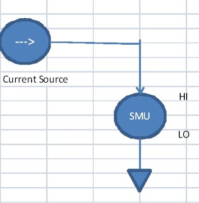
Offset current SMU 4140
I use the SMU 4140 to measure the curves of voltage/current for the transistors - it sets a voltage & I read (not necessarily on the same channel). But I noticed a peculiarity in the data according to the current limit.
First of all, I get different results if I let him autorange device compared to manually set the current limit.
In particular, there is a current lag that occurs for differnent current limits.
In the attached file, the current is allowed to Auto for the Red data and fixed at 100 Ma for data in blue. [the axes are current drain source - ID- & door - Source voltage VGS]
Any idea what is the origin of the offset .02mA in the Red data?
Thank you for following up with an explanation.
Looks like this resource to answer your question:
http://digital.NI.com/public.nsf/allkb/EE869FC813944EAC862578F0005519F5
Tags: NI Hardware
Similar Questions
-
Is it possible to read the voltage/current SMU after the closure of the original session?
What is the method, or is it still possible reading the voltage and current of an SMU SMU-4138 measurements after the original configuration session has been closed? I have a (relatively) long Teststand sequence that sets up the EMS to provide power to the ESA, then conducts tests and along the way I have to take the readings of SMU. I was always under the impression, it is advisable to open and close the EMS quickly set up, but the 3-State programming model does not allow a way to jump into the running state of Init with channels VI, except through committed and engaged States and thus any stop in the process. The power measurement VI only works if you are in the Running State. Seems like a no-brainer, so what Miss me?
bholsinger wrote:
I was always under the impression, that it is recommended to open and close the EMS quickly set up
It's BAD advice. You open at the beginning of your program, you do whatever it takes with it inside your test (configure, read, etc.) program and you don't log off not until you stop your program.
-
Control an SMU-8880 OR through an external system of labview
I worked with a former OR chasis & controller NI PXI 8330 before, but for a new task, I'll use the NI SMU-1078 chassis with a controller NI SMU-8880 and modules NI SMU-4140 & NI SMU-4110. I am confused with the control of this system of labview on a laptop. I tried to connect via ethernet cable, but it is not listed in NI MAX. I would connect it differently or do I need to play with the IP settings?
I don't know exactly why you do not want to do. You can use TeamViewer remote desktop or something like that but, normally I just connect a monitor, keyboard, and mouse. This controller comes with Windows 7 and the frame is smaller than some desktop computers.
-
SMU, used for the measurement of current
Hello
I need to measure current in the range 5 to exit 10uA by a current source PIN. I would have usually connected PXI4065 on this PIN and measured current. But in this case the current to be measured is low.
I have EMS 4130, which has high accuracy of current measurement to 200mA range (0.03%+0.02)uA.
Can I use the current part of the EMS (CH1) measurement to measure current? What should I activate CV outputs (Hi = 0V) who appears in the soft front panel?
Or just without activating the outputs I can measure the current sink. The program of flexible panel displays current measurements, but I don't know if the EMS can be used like that.
Thank you
Not sure NI SMEs, as I have not had the chance to use it yet. SMU of Agilent could be used this way, so I guess with OR as well. You must use out SMU in constant voltage source / I measure mode. Would you say the SMU to hold the voltage at 0V, and allow current to the sink (or source) as necessary to maintain this 0V output.
-
Error:-200277 is not a valid combination of the position and the offset in mx data acquisition
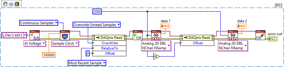
Hello everyone, I use a NI SMU 6361 DAQ in LabView 2013 (32 bit) to acquire samples from six sensors (currently). The signal is a bit noisy, but behave correctly after filter software by averaging, so I dug a little and found the code shown by NOR in this video:
https://www.YouTube.com/watch?v=fkIYp1mqp_g
So far, it has worked great, the loop basically takes anything to run and gives me a signal clean and Nice, but when VI starts first of all, I get the error code mentioned in the title, by saying that I am referencing a non-existent sample, since it is before the first (example 0). He has absolutely zero effect in the real VI, since if I hit continue, it works fine, but as it is for end-user oriented, I don't think they like to see a mistake every time you start up then, did somebody encountered this problem? And if so, how do solve you? Any ideas to spend at least the error message? So far I have tried:
-Insertion of a sample of reading the real while loop, no luck
-Insert a wait for completed task, gives me a timeout error
-Which in fact a little wait to not round, no chance
EDIT: Please ignore the loop for now, it has been used just to show if the data has been formatted correctly and will be used for filtering software, but has no effect on the error.
I'll take a shot at your comments:
-When I run with a simple/general error handler outside the while loop, it reports no errors
-When the error handler is inside the loop (after the reading) it sends the error message, but doesn't give the option to continue
-When I run all at once, with a real constant for the stop condition, it reports the error of loop
-When I run on the execution of highlight mode, it does not report the error once again
All relate to the thrust of the error that you can not collect samples which are periods of sampling of 2000 in the past until the task is run at least 2000 sampling periods to capture.
1. the error in the loop tunnel is only retains the last value of the error. Probably, the loop runs several times where the error is generated, but never seen. Once spent enough time to get samples of 2000 in the buffer of data acq, subsequent executions no longer produce an error. If you stop the loop after this date, the most recent error value is indeed "no error".
2. Yes, you see the error that happened on the iteration 1. The time required to respond to the dialog box is quite probably a long time you * only * see the error on the iteration 1.
3 Yes, as described above.
4. the code runs pretty slowly for the start time of the task until you come finally to the first Read DAQmx is longer than the 2000 sampling periods. Once again, Yes.
Couple of several things:
-Bob comments are super useful and important to keep. Auto error handling behavior are a real subtlety in LabVIEW, not at all intuitively obvious because almost any other terminal output can remain unwired without consequence.
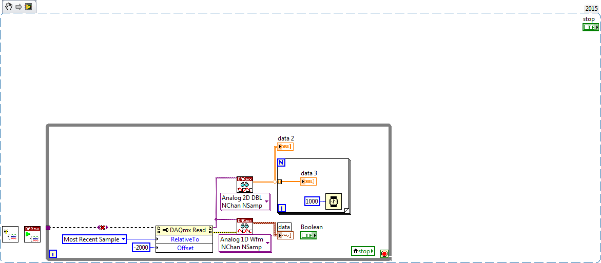
-J' threw together a quick example, mess of my notice to loop before calling with offset = 0. The following works fine without error on my end, using a desktop computer X - card in the series similar to yours. I ran 4 channels at 100 kHz, and then again at 1 kHz without error. The case of 1 kHz took the second planned couple to run to completion and the first Offset = 0 reading has done its job. You can save the pic (save in png format) and then drag the file on an empty LabVIEW diagram to get the instant code. Adjust the device, channels, sampling according to your needs and tell me what you get.
-Be sure wiring in the 'NB of samples' entry on the call of DAQmx Read! When I removed this thread in the example below, I saw your error also. You must connect this number of 2000.
-Kevin P
-
FPGA/FPGA adapter creates 250 mV voltage offset
I use a high-7971R FPGA in a chassis SMU-1073 with the adaptation Module 5782 (DC coupling) and 2016,08 device drivers. When I turn on the chassis and my computer, nothing strange happens. When I try to run something on the FPGA, however, things get weird. Each piece of code works exactly as it should, but as soon as that 'open FPGA reference' finishes running the adapter begins to produce a voltage mV to 0 to + 250 Ai and AI 1. It doesn't go to AO 0 or 1 AO. This shift of power disappears temporarily as long as 'Reference FPGA open' or "Close FPGA reference" are running, but the only way to get rid of the tension of offset entirely is to restart the chassis. Can someone explain to me why this is happening and how to fix it? The FPGA code, I am running can handle a small shift, but this shift seems to be to saturate the signal.
To see the shift: branch I HAVE 0 and AI 1 directly in a 1 M complete oscilloscope.
It is planned. CDA on this FAM (and more high-end a/d converters) have a range of sampling which is not centered around zero. The front end of the compenstates of the FAM for this by applying an offset from the signal which would appear to the user that the range of the ADC is centered around zero. What is different between this FAMILY and other instruments, is that it is not an additional circuit preventing that this lag observed a user of height of the output of the analog input.
You see the shift happen to reference open FPGA is because that's when power to the GPA is activated. The shift should not have an effect on reading which provides the analog input. Just make sure you have impedance corresponding to the source of the signal at the analogue input and you should be good.
-
generation of sinusoidal wave with smu
Is it possible to generate, for example, one 3 a 50 Hz sine wave with SMU 4138 or 4139?
THX
The DCPower API provides no screws to use blocks of power or SME like FGENs. However, it is possible to program the jury at the exit of the standard functions by translating the desired frequency and amplitude to a sequence of continuous output with delays of source is defined so that the output function the user selects is output on the terminals of the device.
The attached program allows you to use a NI 414 x, NI 4135/4136/4137/4138/4139 as a FGEN. As it is, the program is limited to a maximum output frequency of 5 kHz.
I have attached a version of the code for the current output and a version for output voltage waveforms.
-
Hi all
I moved this question here because it is a more appropriate Board.
I'm looking for measurements of current weak on my HAD and therefore seeks to including the guard on my DUT PCB assessment cables. I have two related questions on this issue.
1: the pinout of my SMU-4141 said that there are two pins on guard and I verified this with a DMM, they are linked and lead to the same level as the channel HI. However the cable recommended DB25F-DB25F low leakage cable only has one of these pins connected through guard. Is this correct or is there an error with my cable? I checked all 4 channels and they are all the same.
2: anyone know of any good information / best practices for custody of follow-up on my circuit board?
Thank you all,
Nick
Hi Nick,
Yes thank you, very good, moved to AE a year ago to SRI.
In order to have a reflection and a look at the wiring diagram (which I'm sorry to say that I can't send you in its entirety) and I think I can help with the confusion.
The cable we're actually talking about is not composed of coaxial cables, it is composed of twisted with son of drain and a pair conductive sheath. The son of drain are inert and not get connected to anything, so, leaving twisted pair and their sheaths. There are 8 twisted pairs and gaines in the bundle that gets wired on this connector, which means that 24 potential connections, with pin 13 no wired what whether that make up the number to 25.
Now bear with me I'm sure it's logical: twisted pair number is wired to the pins 2 and 14, which are the two pins of HI for channel 0 in and out. The shield for this twisted pair is then connected to pin 1 (a guard PIN). While guard pin protects both the two pins of HI.
Twisted pair two is connected as well: one half of the twisted pair is connected to pin 3 (LO sense), the other half is not connected and the shield is connected to pin 16. Now if I understand correctly, the son LO need not so much caretaking, so the extra yarn I guess looks more like a thread of drain here.
The schema for the cabling continues like this. Half twisted pair are the SIH strength and direction for a channel that is guarded by a shield wired to an agent, and the other half are wired with LOs and an additional drain.
I don't know why we didn't use COAX when help files, explains using the COAXIAL cable, but I suspect is has something to do with the cost (one of the AEs who graduated from the electrical eng said COAXIAL is much more expensive than the sons of the twisted pair, but he said also it is much more difficult to disassemble to weld so I suppose it would make many of these cable manufacturing) very expensive and difficult).
Now with regard to PCB stuff, I'll be honest, it's not some thing that we have a lot of documentation OR on, but of what google tells me, guard lines can be incorporated in a KIC and from what we have seen in the cable, it looks like we want to keep the HFD for both strength and sense. I myself am a physical grad for PCB design is not something that I've had too much experience with.
What is the next CSLUG meeting (also like the mascot of the group, sea slugs are beautiful!)? I introduce the CLD Summit in early September at the Newbury office if you go to that?
Thank you
Viv
-
How to implement VBW in SMU-5665
Hello master from LabVIEW!
Currently, I am doing a project which involves SMU-5665. My task is to do a pilot for this module and reattached some dataloggin functions. I already have most of the functions (thanks to the example of demo RF Panel), however, I need to implement the VBW settings, which I can't find.
Anyone here done VI for fixing VBW?
Thanks in advance!

Dennis
Hi Denshie,
You can find an example for VBW at the following link:
Examples of measures OR-DAMA Soft Front Panel
https://decibel.NI.com/content/docs/doc-22813In addition, if you are interested in more information on emulation of VBW on the SMU-5665, you can consult the following link:
Emulation of width of video tape and detectors in a vector signals FFT Analyzer
-
Measures of current between 4071 and 2575 sometimes not correct
I use mode of handshake with a PXI-4071 scan list and an SMU-2575.
The DMM is current and the MUX is in mode 1 x 196.
When running the scan list, I have rarely (randomly) get a very small extent to the nA au (when to 4-20 MA). I'll run the scan list again and that the channel will be correct, so it seems not to match a channel.
I tried to increase the time of settling of the DMM and the MUX, but have had no effect.Any help would be great.
Thank you
Caleb Swieson
After further tests, we determined that it was indeed the devices to measure who pulled out the very low currents. So it wasn't the fault of the hardware. Oops
-
R series: compared to current output output impedance adaptation
Hello
I wonder about the output impedance specified for SMU-782xR and some other adapter module ike l 6581.
The specified output impedance is 50 ohms. To get the best signal integrity, it is imperative to adapt the impedance using a cable (transmission line) with a 0 hm 50 characteristic impedance and impedance of 50 ohm load.
But I don't understand how this is possible, because with a high level of 3.3 v, the output current proposed spindle must be 66 my. The current per output pin max 7821R is 4 my.
This FPGA offer 128 pins, so that the maximum total output current should be of 8.5 A, so 28 w. It's not realistic!
Could someone explain why outputs are 50 ohms?
And how do I adjust the line and the termination of employment?
Thank you and best regards,
Benoit Chantepie
Benedict,
After some thought, the concept of the output impedance is really not applicable outputs logical digital because they spend most of their time in the saturated States and time spent in the transitory States is not usually specified with the exception of the time limits.
What is your purchasing process is I would ignore the specification of output impedance. Watch the voltage and current limits. If those who do not meet your needs, consider external buffers. You can specify the buffer to meet the requirements of your testbed (including protection against defects if necessary) and to meet the specifications of the devices OR.
Lynn
-
We are currently assessing module SMU - SMU 4137. We love the ability to measure low noise and the amps of output of 1 a. However, we are concerned with the ability to output 200 VDC. During normal use, we would never go more than 20 v DC, but if the module has got somehow given by accident at 200Vcc that could be deadly to someone touching the output contacts.
The module has a limiter of voltage of equipment that we can define so that it never turn off more than 20V? I do not trust that the remote control the guaranteed value of the security, because someone could accidentally activate the output 200Vcc.
Thank you
Patrick
I did not create these yet, so I can't test it myself. But the manual says "with lock open terminal security level/limit the output voltage is limited to +/-40 VDC and protection will be triggered if the voltage measured between the HI and LO terminal exceeds +/-(42 Vpk +/-0,4 V).» My reading was that he could operate in low voltage without a safety switch connected. In addition, it looks like all the limits that you can set are made in the software.
-
Setting IP error incompatible. SMU-8135
Hello NOR Forum,
I recently got a new laptop. I want it to work with the NI SMU-1078 chassis with controller Embeded PXIe-8135. I'm having a problem to connect to it. There is an error in Measurement & Automation Explorer > remote systems > NOR-PXIe8135-# > status "Incompatible IP Settings."
I tried this http://digital.ni.com/public.nsf/allkb/A0F6EFF8A33578948625749C006DEC3B , but it wouldn't let me change my static IP address. Help, please.
Hey waterox,
1 take a look at this article, because it seems to apply to your current situation-
Why can I not connect to my PXI real-time (RT) target on the network
http://digital.NI.com/public.nsf/allkb/24D16468DE8838B2862568E200746D7E
2. reformatting of the target can be a quick way to solve this problem. You should be able to configure the IP address of the target once reformatted.
3. make sure that your network card settings are correct on your host computer. The following document describes the process with a CompactRIO which should act the same as your real-time target.
Configure the CompactRIO with a static IP address
https://www.NI.com/getting-started/set-up-Hardware/CompactRIO/static-IP
4. how many NIC's a laptop? You have active Wifi? If Yes, take a look at this-
Best practices for using multiple Interfaces (NICs) with products OR
http://www.NI.com/white-paper/12558/en/
I hope this helps!
-
I have observed 4132 PXI is sometimes load dependent. We were testing a specific device
which is part of the bi-directional and when we forced a current through the device in the negative sense of the whole
current is not available through a device (i.e.) when I force - 1mA through the device, I would see a 1mA through the device.
However what we observe, it's only 0.5mA is available through the device. This happens only in the negative sense.
2.) I have observed this behavior for a specific device. We tested the same device on keithley 2611 and they
measure well. In my view, that the problem must be with the EMS.
How much output impedance is present in this SMU? How can this problem be solved?
-
I use a 4130 PXI SMU to test a 3V battery transmitter RF. The unit goes through a sequence that requires up to 20mA current then goes into standby mode that should attract current in the low range AU in operation. The problem I have is downranging the 4130 available lowest range. The idea is to turn on the unit with the SMU put on the beach of 200mA. After the passage of the device through his power over the cycle, I need to change the range up to 200mA range and measure the off current. It seems that the EMS is change only from the beach on the initial installation. Attached is a snip from my code, any help is greatly appreciated.
Hi Phil,
I have rebuilt your code and was able to recreate the error you experienced. I think I have an answer for you.
You need to replace the VI niDCPower initialize with the niDCPower initialize VI channels. The difference is that the VI initialize the session with the SMUS in the State, is not the case to initialize it with Options of VI. For this reason, you should also place a niDCPower VI launch before your niDCPower configure output Enabled VI. Programming of a NOR-DCPower session States are described in the link below:
Programming States - OR DC power supply and SMU 1.4 Help
http://zone.NI.com/reference/en-XX/help/370736F-01/ni_dc_power_supplies_help/programmingstates/I have also included links to pass on the details of the various functions involved in the code:
niDCPower initialize VI - OR DC Power Supplies and SMUs 1.4 channels help
http://zone.NI.com/reference/en-XX/help/370736F-01/nidcpowerviref/nidcpower_initialize_with_channels...niDCPower initialize VI - OR DC Power Supplies and SMUs 1.4 help
http://zone.NI.com/reference/en-XX/help/370736F-01/nidcpowerviref/nidcpower_initialize/niDCPower run VI - NI DC Power Supplies and SMUs 1.4 help
http://zone.NI.com/reference/en-XX/help/370736F-01/nidcpowerviref/nidcpower_initiate/After making the changes I described above, I was able to run the code without generating an error.
Maybe you are looking for
-
Thunderbird crashes when you click the link in the email.
Thunderbird v31.4.0Linux Mint Debian Edition 3.1.2 - amd64Cinnamon 2.0.14 When you click on a link in an email, the system hangs and the screen displays jagged, diagonal lines. Cold start is required. This can be repeated. Same results running in Mod
-
By clicking on a link upens two tabs
As I got FF 14.0.1 I had a problem maybe 33% come from the time I click a link, or FF in Outlook and FF will open then two tabs for the link. This is ongoing since I've upgraded to 14.0.1 and it is aggravating.
-
RtHDVCpl.exe impossible to locate the component
IAM getting this error at the start of the system (rthdvcpl.exe)
-
OfficeJet 6500 E709n: for 6500 Device Manager
I just transferred an officejet 6500 portable Mac on my pc Windows XL. I noticed on the laptop, an HP device at the bottom of the screen area manager there, but there is not one on the pc or in the system tray or the HP folder. The installation not b
-
Can not receive mail getting error 0 x 80004005
Original title: cannot receive email___My another computer is configured EXACTLY the same and I get everything - just stopped receiving the An unknown error has occurred. Account: 'Beautiful', server: 'mail.comcast.net', Protocol: POP3, Port: 110, se