Spatial data acquisition Oracle through WFS
HelloI did research for a while and am a bit confused.
I have Oracle Spatial 11 g with geometry data and would like to be able to retrieve these data through a WFS for a viewing application.
Here's where I'm confused:
(1) space offers a WFS service must be configured. If I set this up, I would be able to access the data through getFeature URL commands? The documentation I see for them has applications for getFeature in the form of XML files, so I don't know if I can do it. Also, it seems that the service returns the .log files, but I think not I want GML...
If this is the option that I must take the tutorial to configure OC4J and Web Services are for a Linux (http://www.oracle.com/technology/obe/11gr1_db/datamgmt/spatialws/spatialws.htm)--are there one for 64-bit Windows?
(2) do I need an another "application layer" to enable support for this URL? I know that MapServer can use URL requests... can I run against the data in my PB and forget the WFS Oracle?
(3) MapViewer seems to work with themes WFS and process applications through Java and SQL... It's another option?
I'm basically confused as to where everything is and what I should focus on to get my spatial data of the DB through a WFS. Any help on this would be greatly appreciated!
Thank you!
Yes, with a server Oracle Spatial and logic of the Web, you can get support for WFS.
Note that you must space Oracle 11 GR 2 to work with the logical Web server.
MapVeiwer can only consume the WFS themes, so it does not help with what you want to do here.
Siva
Tags: Database
Similar Questions
-
You can trigger through communication Modbus TCP/IP PLC data acquisition without using a loop for?
Hello
I am trying to contact a facility through a Modbus TCP/IP communication PLC. I'm new to this method, but the idea is that the installation will send the logical (Boolean) values 1 bit by ethernet to my workstation which read and then will begin data acquisition. Basically, I need a triger to come to my pc. I placed my vi inside a structure case T/F which will run according to the signal, it receives data acquisition. However, for it constantly waiting, I put this in a loop for. The works of vi, but playback signals sometimes lagging behind due to the loop for. If I take the loop out and just run labview permanently, it works perfectly, but I know that the option is only for debugging and should not be used. So my question is, is there a better way to wait for an incoming signal?
Hello!
Please note that the order of execution of the write operations on the shared variable 000002 is not determined.
For example, nothing prevents this order of execution:
(1) value false 000002
(2) set to true 000002
(3) execution of the loop
In what concerns the delay, you might consider placing a waiting vi in the case of 'false', or the loop uses 100% of CPU if I'm not mistaken...
Kind regards
Marco
-
not able to write the data through data acquisition
Hello
In fact, I need to send a code word (text file) from the program matlab through my data acquisition (OR-USB-6215). my program (transmitter.vi [case structure: page2]) attached below has a problem to do the task. whenever I run the program it gives me an error like
Error-200479 occurred at DAQmx start Task.vi:2
Possible reasons:
Measurements: Specified Operation cannot be performed during execution of the task.
Task name: _unnamedTask<84>
At the moment I don't see output in my oscilloscope. But, if I highlight my performance I observe my samples on the oscilloscope with the following error message
200288 error has occurred in the DAQmx write (analog 1-d 1Chan NSamp DBL) .vi:3
Possible reasons:Measurements: Attempted to write a sample beyond the final sample generated. The build is stopped, so the sample specified by the combination of the position and the offset is never available.
Hi Raja,
What I did is I moved the 'write DAQmx' outside the while loop. That made the VI in this case is read the file and passing it to a table, and then this table is formatted a waveform to be written to the data acquisition device.
With respect to the way in which the data is read, I don't change anything, it was based on your original code. A good way to know if you write the correct data is to check the chart view in VI.
So the question is, is the graphic display showing the good waveform?
Best regards
Faris
-
Seeded data for Oracle Spatial 10 g
I have a fundamental question about Oracle spatial. Oracle Spatial data seeded as US maps? For example, a store if I update the latitude and longitude, this information allows to know location and the city of the location.
If Oracle Spatial has no data seeded, what options are available to implement the same in Oracle spatail.
A quick response will be appreciated.
Thank youHello
Space Oracle does not provide the content of the map. Some providers of content such as Navteq provides the specific format of map/routing/gecoding Oracle.
If you want to discover the location (lat, lon) of an address, you can use Oracle geocode (sdo_gcdr.geocode).
If you have a location (lat, lon) and you want to know the address information, use the geocoder Oracle (sdo_gcdr.reverse_geocode).Please see Chapter 14 SDO_GCDR package (geocoding) http://download.oracle.com/docs/cd/B19306_01/appdev.102/b14255/toc.htm (Developer's guide space 10 gr 2)
Jack
-
Data acquisition reading incorrect when you use a loop
Hello
I wrote a simple VI (00, 01, 10, and 11) output to a circuit connected with 4 resistors. Based on what value the ciruit receives, it passes current through a particular resistance. It is again entered in Labview and traced.
The problem is when I send a particular value (i.e the 00, 01 and 10 and 11) and get that back, it's okay. But when I send and receive the consectively connected via the loop counter, they are incorrect (not synchronized with the number of the loop).
I made sure that circuit works very well. It has something to do with the loop synnchronization, reset, value compensation, etc. can be.
Please Guide...
Change your DAQ assistant that reads to be 1 sample on request.
Right now it is set for continuous samples. And 10 samples at 10 Hz. Then it runs and starts. The next iteration, you send a new digital out, but the wait for 4 seconds. When you read again, you get the next 10 samples that are put into the buffer of data acquisition, but now 40 samples have actually entered the DAQ buffer. In time your DAQ buffer will be finally complete and raise an error. In the meantime, you will continually read data continues to become more tainted by the iteration.
-
motion control for vertical actuator and data acquisition
Hello
I am a researcher (a branch of civil engineering) geotechnical engineering and I have very little knowledge about the acquisition of control and data motion, so would need a lot of help from the experts OR. I have only knowledge base on these 2 aspects based on my reading of some materials on the Web site of NOR and youtube videos, so I hope that you bare with me
 . Here are my questions:
I am trying to build an actuator which will be used to push a probe (a penetrometer with a load cell to measure the resistance of a soil sample), resembling the concept, photography in the attached file. I need to have these criteria for my system:
(1) actuator, which can push the probe at speeds between 0.01 mm/s - 300 mm/s with precision and move the probe cyclically (upwards and downwards) in the vertical direction
(2) load expected on the probe into the ground range: 0.02kN - 6 kN.
(3) necessary to get the load cell load data and the speed of the probe.4) able to control the actuator to a PC (speed and posotion) and monitor data from transducers and data log time even the transducers.
Guess my beginners is that I will need:
For orders:
(1) software - LabVIEW and NOR-motion assistant(2) controller - NI PCI-7342
(3) driver/amplifier - analogue servo AKD Drive
(4) motor - motor brushless servo AKM
For the acquisition:
(1) software - based LabVIEW development systems(2) amplifiers or other device - no idea what type on the conditioning of signals
(3) data acquisition device - no idea what type
Since I'm a beginner, is - that someone might recommend components (hardware and software) for the control and data acquisition. I'm on a tight budget, so I thankful if someone could help me to recommend components good enough to build my system.
Thanks for your help.
At these rates, you will need to run the sensor for the cDAQ. You can configure the analog output on the Tritex nationally on the position. There is an adjustable filter that you can set in order to get a clean enough to 300 Hz signal. When you learn about the Tritex, make sure that let you them know what comms and e/s that you want to use. If I remember, not all options have worked together. The analog output may need to be my, but you can put a resistance through the acquisition of input data to get the voltage instead. I don't remember all the details. You should really not too much on the Tritex/LabVIEW side. You will send your movement parameters (beginning of end of race, speed, position, accel, cut), and if you cycle (I believe you) or simply running in a loop. You could also just be able to use the functions of jog. When you get close to knowing exaclty what you need, PM me and I'm sure we can work something out with the drivers. You need only the basics. In fact, you could probably do this all your movements via digital and analog i/o.
-
HP laptop - 15-ac022ne: pci of data acquisition and signal processing controller
I have this laptop HP - 15-ac022ne and I got windows 8, evrything has not been totally perfect until I upgraded to windows 10, wireless function no longer works, tried to install the driver and update, it was succsessfully installed in the machine to say, but still not working and PCI data acquisition and signal processing controller driver is missing tried to download the chip set on the driver support page, does not, tried to update the driver through the Device Manager and the message can not find a driver for the device of said...
Please I need help...
Hello:
You need this driver for pci data acquisition and signal processing controller.
-
LeCroy Waverunner 640Zi - Data Acquisition
Hello... I'm trying to set up my oscilloscope waverunner with LabVIEW SignalExpress for data acquisition.
I took the steps so far:
1 pulse generator hooked to scope of signal generation
2 USB scope to the installed computer with LabView
3 downloaded lecroyscope driver 3.2.9 - x 64
I turn on the scope and plug in the USB to the computer and SignalExpress begins.
a. start by using data acquisition
b. Add step/aquire signal / IVI aquire / IVI brought aquire
c. create new IVI session... resources descriptor (I choose my USB device ' USB0::0x05FF:0 x 1023: 2812N61507:INSTR '), I select the right driver (lcscope), and I do not click enable simulation data, press ok
d. I still receive configuration errorse. did the research... some forum said goto MAX, find drivers and uncheck the Cache and the exchange of check
f. attempt to initialize... always get config errors.
g. return to MAX... change to simulate with specific driver.
h. initialization works... NO errors, BUT no data are acquired.
Help, please!
Hello
Sorry to jump in if I was out of the country for a while and am still catching things in my office.
I think you are looking for someone to say yes, "you can connect to the scope with NOR-MAX and VISA, and here's how interactive tool do"
A few things:
LabVIEW for XStream extended driver is the right one. It works with all the TeledyneLeCroy Windows based scopes.
As I see has already been noted. (I'll give Kudos soon), the scope of application must be configured to use interface USBTMC. To do this, go to the drop down Utitlites on the scope menu and select "utilities configuration... '. "in the tabs that appear at the bottom of the screen, select the 'Remote' tab and make sure that the interface type is set to USBTMC. This will also show you the VISA resource (I see it in the title of the image of VISA interactive tool indicated in a previous post).
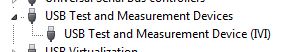
Once this field is selected, the PC should detect the USB connection and install the device. (you can see in your device manager as a Test of USB and the measurement device):
Once this is done, you can then enter the NOT-MAX and it will detect and display resources. You can now communicate with the device:
If you have problems, do not hesitate to give me a call and I'm happy to walk through it over the phone.
Kind regards
Leonard Brown
Technical sales engineer
Teledyne LeCroy
1-800-553-2769 -
Several timers loop data acquisition
Hi all
I am developing a VI for FPGA Deployment. My equipment consists of a chassis/controller for cRIO-9072 with module 1-9211 thermocouple, card SD-1 module, 3-9215 HAVE modules and universal modules 2-9219. I will collect data of two thermocouples on the 9211, 14 channels on 9215 channels and 6 on 9219 modules. This system communicates to the host via ethernet.
I have prepared a vi (see attachment), which used two DMA FIFO for writing data to data acquisition at a different speed. I will be sampling the s and 9211 9219 much more slow (500ms by samples), than other channels (40 ch/kech. / s). Currently, my FPGA vi trying only to taste two different modules. When I run the present on the host vi and try to read the data, I get only extracts of the data at different intervals. If either of her would reveal latency with the connection or the host vi failed to refresh quite quickly? I am relatively new to labview, so any help is appreciated. Thank you.
Gaussy
Hi Guassy,
There are a few things that you need to change:
(1) you must separate your acquisition in the FPGA in two separate loops if they have to operate at different speeds. As it is, probably will run at the slower speed of the two parameters.
(2) you must do the same in your VI in real time, or set up the DMA readings so that they will be read at the same pace. For example, suppose that a single module acquires 1000 hz and the other at 200 hz. If you want to read 100 samples from the first module (so your reading will occur at 1000 hz / 100 samples = 10 hz), you will need to read 20 samples from the slower module, so it is synchronized with the first module.
(3) your timeouts are too short on your DMA readings. Your slow acquisition is 500 us. It will take 50 ms to read 100 samples requested, but the delay is set for 10 ms, so 4 times over 5 playback will return nothing.
(4) you use graphics and no graphics. A chart will only show the current data buffer that was written for her. Refresh rate of the façade is nondeterministic, so that you can't see every update. If you use a chart, the chart will record all data written on it to the indicated depth (default is 1024 elements).
Also remember that you can have three FIFOs DMA between the host and the target FPGA, so use them wisely. It is often easier to perform your purchases on the FPGA at the same pace and send them through the DMA FIFO even in VI in real-time. If you need a few channels to connect at a lower rate, you can always throw the excess samples (there are some decimate wave screws that are perfect for this).
I hope that helps!
-
We send 5v data acquisition using a voltage generator. Hook us it up to a voltmeter and see 5V. When connect us the generator voltage to a valve "normally open" parker, the voltmeter indicates .14V. It seems that when we connect the two sons of the valve for the voltage generator, the son act as pattern. We want to control the voltage flowing to tap through Labview. We checked the wires to the valve and they work very well, because if we send a constant 5V since the acquisition of data and put ashore, she, the voltmeter indicates 5V. Someone knows why the son act as pattern and low blood to .14V?
nsatpute wrote:
Our data acquisition is NI USB-6259. The valve requires only a 5V max and our DAQ provides up to 5V. However, after connecting the valve to the acquisition of data, the grave tension to almost 0. We start from the principle that the son somehow act as the reason, but we are not sure if this is the case.
The question here is not how much voltage the valve wants, it's the current needs of the valve. The 6259 can put only 5mA via an analog output. Your very likely tap needs much more than that. If you need to add in an amplifier circuit that can supply more current to operate your faucet.
-
Control and simulation and data acquisition
Hello
I am applying to motor control in Labview. I'm sampling speed from DC engine in real time through an acquisition of data. (my sampling time is 1000 samples per second)
Then wrap speed as input to a Simulation (simulation and design of the order) and inside the loop simulation, I have a PID controller. The PID has the actual speed of the engine for the acquisition of data and the engine reference speed as input.
Reference engine speed comes from the generator of signals (control design and simulation-Simulation) and is a waveform.
My step in the engine size is 1000.
I am running this application real-time and drawing the reference signal and the motor real signals. I run into several problems with regard to the calendar.
1. when I change the size of the step of the simulation loop, the frequency of squares of reference also seems to change. For example. What step size = 1000, duration of pulse = 1 s. What step size = 100, pulse width = 0.1. (My pulse frequency is 1 Hz, Simulation clock - 10 kHz). How step size can affect the pulse width.
2. can you explain the relationship between the DAQ, the Simulation step size loop sampling time, Loop Simulation period.
3. If I want to collect different sets of data using sampling different hours, it's OK to change the sampling DAQ time without changing the size of the step of the simulation.
Would also like to emphasize that the DAQmx calendar under sample clock mode is placed in front of the simulation loop and the output is connected to the loop simulation.
Appreciate any help.
Hello
Maybe some screenshots of your code would help. Furthermore, what you have read your samples together with your DAQ screws?
(1) If you have a waveform, the output is specified as:
For example, if you change the size of the step of the simulation loop, you change the simulation time which are introduced into the signal generator and affecting the waveform that you see if you do not have a size quite small step to characterize the waveform that you generate.
(2) sampling DAQ rate is the speed at which samples are taken on the acquisition of card data itself. The size of the simulation step, help. "Specifies the interval between the time when the ODE Solver evaluates the model and updates the results of the model, in a few seconds." Simulation loop, still using, "Indicates the amount of time that elapses between two subsequent iterations of the loop of control & Simulation.". " "Step size determine the value of t that is introduced to the functions you use in the loop simulation while the loop simulation period controls simply to how fast you change the following t value. The sampling rate of DAQ hardware is a clock of completely separate hardware controlling the analogue-digital on the DAQ card converter so that you can get a deterministic dt between the samples being acquired.
(3) you can change the schedule for the acquisition of data, but you will need to restart each time the changes take effect. If you change the calendar of data acquisition and want your values to correlate with your simulation, you will need to change your size of step as well.
-Zach
-Zach
-
Measurement of low-cost input analog (4-20mA) with data acquisition
Hello
I would like to have a very low cost measurement system loop which I can plug in my laptop current:
I have a load, which is connected to a circuit of air conditioning/signal booster, which output a 4-20mA. I want to measure this current loop signal.
An idea for the lowest cost system? I think that the most NOR DAQ are too expensive and too exaggerated.
I have LabVIEW.
Use of remote sensing current low-value resistance, then measure the fall of voltage through it with the help of an acquisition of data 6008/6009? They have about $150.
You will probably need to amplify current-sense with a MAX4372 or similar resistance to achieve a result that allows you to use a reasonable scale on data acquisition. I measure the current through our products in almost all of our equipment to test in this way. The size of the resistance of meaning as a result. The 6008 is accurate enough, but it is not the fastest nor well presented. But starting at $ 150, they are hard to beat.
-
Average data acquisition alternating window 25sec
Hello
I am relatively new to programming and LABVIEW and was hoping to get help.
I am analyzing the retinal potential obtained in answer to Flash (ON and OFF) model 120 LEDS (simultaneously)
The rate at which the LED on and OFF depends on a pulse of squares of 1 Hz and 5V amp (from the device).
I use USB-6009 to convert analog signals.
Data are collected for 50-100 scans (LEDs go ON and OFF), is - 25-50 s of data collection. Followed by a break (no data genuine collected) from 25 to 100 seconds, after which a new cycle/game data are collected for the next dry 25-50 and so on. Sampling rate = 1000 Hz (1ms/point).
My goal is to perform an average of data collected with the timestamp. Display the waveform of flood and averaged over the waveform graph and write the data on average in an Excel with a time stamp.
Attached is a diagram of what I expect, I need a direction to start and move forward.
Help, please
Thank you.
Hi Lana89,
Since this is a simple data acquisition task, you can go through the sample data acqusiition and move forward.
Kind regards
SrikrishnaNF
-
choice of the model of design for data acquisition system
Hi all
I have a problem on the selection of the model design / architecture for a data acquisition system.
Here are the details of the desired system:
There are data acquisition hardware and I need to use by looking at the settings on the user interface.
the period of data acquisition, channel list to analyze must be selected on the user interface. In addition, there are many interactions with the user interface. for example if the user selects a channel to add scanlist, I need to activate and make it visible to others on the user interface.
When the user completes the channel selection, then he will press the button to start the data acquisition. Then, I also need to show the values scanned on a graph in real time and save them in a txt file.
I know that I can not use producer consumer model here. because the data acquisition loop should wait for the settings to scan channels. and it works on a given period by the user. If the loop of user interface makes higher then loop (loop data acquisition) of consumption. This means that queue will be bigger, larger. If I use notifier this will be some data loss comes from the user interface.
y at - it an idea about it? is there any model of design suitable for this case?
Thanks in advance
Best regards
Veli BAYAR
Software for embedded systems and hardware engineer
Veli,
I recommend the model producer/consumer with some modifications.
You might need three loops. I can't tell for sure from your brief description.
The loop of the User Interface responds to the user for configuration entries and start/stop of acquisition. The parameters and commands are passed to the Data Acquisition loop via a queue. In this loop is a machine States that slowed, Configuration, Acquisition and stop States (and perhaps others). The data is sent to the processing loop through another line. The processing loop performs any data processing, displays the data from the user, and records to file. A registrant can be used to send the Stop command or stop the loop of the UI for other loops. If the amount of treatment is minimal and the time of writing files are not too long, the functions of processing loop might be able to happen in the case of the UI loop timeout structure of the event. This makes things a little easier, but is not as flexible when changes need to be made.
I'm not sure that there is a type of design for this exact configuration, but it is essentially a combination of the models Design of producer/consumer (data) and producer/consumer (events).
Lynn
-
Unknown device named "PCI data acquisition" and signal processing controller in Device Manager
Greetings,
Yesterday, my brother, who was running Windows 8.1 Overview on his Asus S400CA Ultrabook fell on a big problem of the NTFS partition corruption that made it impossible to recover through the Refresh Utility Windows 8.1. Given the situation, my brother decided it was better to go back to Windows 8, I had to install Windows 8 on their PCs by using an external DVD drive with a Windows 8 x 64 installer I already buy plenty of detail. The computer never asked me for a product key that I have read is normal in Windows 8 PC now having these embedded in the motherboard. So far an installation smoothly, but he's going to be delicate in the part of pilot facilities. Before you remove the computer I went to the Asus website and did my best to find the specific drivers for my brother's computer and downloaded the key drivers, chipset, audio, intel graphics card, bluetooth, trackpad Wireless LAN, LAN and Asus and installed. I used Device Manager to check that the drivers have been installed and which did not exist. I was able to get most of the drivers installed properly, however, said the Device Manager miss me the pilot of "Data Acquisition and Signal Processing controller PCI. Unfortunately I go to Asus website to see that if I can find the driver however, I can't do this right now.Check the attached screenshots for visibility...I also tried to use Windows Update to see if he could find the correct driver and unfortunately it's a dead-end. Because of that I write in this forum to see if someone can point me in the right direction when it comes to this missing driver (and others) indicated in the Device Manager.One last thing that I would ask is if I can use a utility like DriverMax to find missing drivers or should I go and install it manually?Thank you very much in advance for any help on this matter.Original title: cannot find drivers for Asus S400CA Ultrabook PCIHi Mike,.
Please keep us updated on the status of the issue. Please do not hesitate to answer, in case you need help with Windows in the future.
Good,
ASUS technical support according to my brother was a bit of a dead end, so I went to another Google search and found the culprit. I was missing the following drivers of ASUS:- Intel® dynamic and thermal platform frame driver
- ASUS Wireless remote control (a driver for you to enjoy the airplane mode (Wireless) On / Off)
The first pilot took care of the Acquisition of ICP data and Signal Processing controller and all but one of the unknown devices. Finally, the other took care of the last unknown device in Device Manager.I never thought that ASUS would use this a strange name for their driver because these names are extremely misleading.Other than that, I can finally say with certainty that the computer of my brother is back in business, and I can call this comprehensive process of restoration of Windows 8.Thanks for any assistance to Zaki J, I appreciate much all advice through this process!


Maybe you are looking for
-
iMac suddenly beach balling a lot
Especially with Lightroom CC when it opens files. I see a few HD errors in the audit of the being. Does this mean I have to replace the drive? EtreCheck version: 2.9.6 (256) Report generated 2016-02-22 15:32:37 Download EtreCheck from http://etrechec
-
laptop does not start at the operating system hp mini 1154nr
Hi all Can I please help determine if my hard drive is bad or is there something I can do to fix this? The problem im having is that my computer hp laptop mini 1154nr at startup hp scren with f9 and f10 display on screen. I press f10 and then exit th
-
I just bought the new Macbook to 2015, a week or two ago and I just noticed today that the screen has several spots that can be seen when it is on a black background. I tried to clean the screen several times, and they did not disappear. Any thoughts
-
HP - Compaq ProBook 4520 s: HP - Compaq ProBook 4520 s compatible RAM upgrades
Hi guys! I bought the HP - Compaq ProBook 4520 s and I plan to upgrade my memory (4 GB of ram). Is PC3-12800 unbuffered NON - ECC 1.35v or PC3-10600 1333 - PC3 compatible? Can anyone suggest me what is the most compatible? Thank you!
-
Web Works SDK Installation stuck on the first Page
Hi guys, I installed SDK WebWorks on my Mac OSX 10.8. I have java version 1.6.2. However, when I run the installer, it asks me to enter the Admin password and then, it launches the Installation Wizard of anywhere. It presents the first screen with a