Spectral histogram of adc output
G ' Day all the
I have a LabVIEW task that I'm confident should be dealt with before (several times). However, not for the life of find me a solution documented. It's displaying a range of possibilities of an ADC on a histogram channel (no, not the statistical flavor - the spectral version of science).
I have a 8 k ADC front-end DAQ loop which (for reasons of this example) gives me the amplitude of incoming impulse (value between 0 and 8191). In this loop, I would a 'live' spectrum in real-time of the cumulative number of hits by way of the ADC.
I can think of ways using an 8 k array and incrementing the bins manually but how to get the data in the table persistent in the loop... and actually display.
If I have to invent my own wheel to solve this problem while it is OK, but I'm sure that like most of my brothers of coding, I'd rather use someone else
See you soon
Steve
Look at this example of a histogram. Which is similar to what you need?
Tags: NI Software
Similar Questions
-
I need the raw ADC output card PCI-4462 using DAQmx
I need the raw ADC output card PCI-4462 using DAQmx
Is it possible or are only regulated units availible.
Ken Manatt
There is a version of 'Raw' DAQmx Read (see image). This is probably what you are looking for.
-Alan

-
Performance outputs analog 4461
I'm generating a sine wave of 1 kHz to 1.5V waveform DC offset and 800mVp. I use this signal to test a 12 bit ADC. As indicated in the attachment the best I can get is - 70dB on the second harmonic, which is to be able to test only a system of 11 bits. I need better that - 75db on the 2nd harmonic. I use the output in an active probe impedance high through a HP being a 24-bit DAC I thought that it would be able to perform this task. What Miss me? I've also attached the LabVIEW code that I use.
John
-
myRIO ADC problem: side affacted channel of its previous channel
Hello
I use several channels ADC myRIO now and facing a question about it.
I use 3-channel ADC Port A: AI0 AI1 and AI2.
I have connected AI0 in the middle of a potentiometer for voltage accoss it. And connect anything to AI1 and AI2.
CDA works very well. I can move the potentiometer valtage perfectly AI0.
However, when I changed the value of the potentiometer, the CDA of AI1 and AI2 results changed also, 0, 1V to 0.8V about. Please note I have nothing plugged in these two ports.
Is this true? the ADC AI1 and AI2 and AI3 same (PORT A) port are affacted by AI0?
When I connected AI1 to an Anolog output senser, the result was also affacted by the potentiometer which was connected to the AI0.
When I connect AI1 in power, he was out of influence.
Did someone already had such a problem? Can someone help me to solve it?
Thank you
Fisher lah
It is the response of support OR:
Please note the small change you notice when both of your strings are attached can be due to several factors such as the wrong wire shielding, etc and EMC (electromagnetic coupling).
What is a floating channel terminal, random or variation is normal and due to internal correlated myRIO circuits and should not be a cause for concern.
Well, I'm still very confused.
-
Spectral power sinewave AWR VSS level
Hi all
Could a good colleague AWR user wanting to help me with responding to a question concerning my use of a measure of the power spectrum - use of the SPECTRUM of VSS-> PWR_SPEC function?
It's a simple question, but I think I need help from experienced users of AWR to help me.
In VSS, I simply used a sine-source to generate a sine wave of 1 kHz with an amplitude of 1V (PIC)... in other words 2V peak-to-peak. Then I simply put this sinusoid through a real signal to the converter complex (R2C) module. And then I put in place two simple measures of VSS. A fair measure was to observe the time - the wave of the sine wave - to make sure that I was getting 1 kHz and 1V (peak amplitude). The other measure involved simply by using measurement of PWR_SPEC to look at the spectrum of the sinusoid.
For a sinusoidal 1V peak, I calculate that the RMS 1/sqrt (2) amplitude. And if the reference resistance is 50 ohms, so I calculate that the power of the sine wave (Vrms ^ 2) / 50, which is 10 mW (IE 10 dBm).
For the sine wave spectrum, I expect to see two spectral lines, one at 1 kHz with an amplitude of the component of 0.5 and a to 1 kHz (negative frequency) also of amplitude of the component of 0.5. In terms of power and with a 50 ohm reference resistor, then is the power in the component of 1 kHz (V ^ 2) / 50 = (0,5 ^ 2) / 50 = 5 mW. And the power of the component-1 kHz is also 5 mW. Thus, the sum of the power of these two gives 10 mW, which is what I expect because the total is equal to the computed RMS power above (in the sine wave).
Now, in simulations of VSS, simulation results are indicating that the power of the component 1 kHz is 2.5 mW (i.e. 3.979 dBm). And also indicates that the power of the component-1 kHz is also 2.5 mW (3.979 dBm). So the results of the simulation, the total power is 5 MW, which is exactly half of the value I want.
So for now, it seems that the levels of spectral power of the simulations of VSS components are always 3 dB LESS than what I calculate. So half the power is lost somewhere.
Can I ask other users of AWR, if I set up the simulation properly (or not) and point me in the right direction? I think I'm just not using the Simulator correctly and just need some advice to put me on the right track. Or if I get things set up properly, then I'm missing an important step as the calibration for the measurement of another point of reference?
SINUS block with a complex output, by default, uses the representation complicated envelope with a frequency equal to that of the sinus. So, if you place a measure of its output waveform, it will display a constant power of (1 + j0). The CTRFRQ = 0 setting will allow you to 'Center' of the signal in the DC and see a sine wave at its output. The spectrum of a complex sound signal will contain only a single tone to + value of the QRU. The two points to + FRQ and - FRQ, with 7 dBm power, each will be displayed only for a real signal if you view all frequencies in the spectral measure.
You can find detailed information on this subject, as well as calculating corresponding, by doing a search on "complicated envelope representation" online. The main thing is that the complex representation of a sound signal will be A * [cos(2*pi*f*t) + j * sin(2*pi*f*t)]; However, when you use R2C you get only the real part, A * cos(2*pi*f*t), therefore half of the power you would get a SINE block with an exit node complex.
-
I use the outgoing/incoming analog DDK with the DAQ 6341 SMU map.
The examples, for example aoex5, show a single timer (method outTimerHelper::loadUI), but the example shows the DMA loaded with same size of vector data.
There is a comment in the outTimerHelper:
 call rogramUpdateCount, which implies that memory sizes different pad per channel can be used.
(the comment is: switching between the sizes of the various buffers is not used)
Nobody knows what should be the format the DMA buffer for data from multiple channels with different frequencies?
For example, we want a0 with a sinusoid at 1 kHz and a1 with a sine wave of 1.5 Khz. What looks like the DMA buffer?
With the same frequency for each channel, the data are interleaved, for example (ao0 #0, ao1 #0; ao0 ao1 #1, #1,...), but when the frequencies for each channel is different, what the stamp looks like?
Hello Kenstern,
Data are always intertwined since each card has only a single timing for each subsystem engine.
To AO, you must specify the number of samples that will be released to the AO. You also specify the number of channels. Because he didn't is that a single engine timing for AO, each AO will be channel will be updated at the same time to update clock tick. Data will be interlaced exactly as shown in the example because each channel AO needs output at each tick of the clock to update. The data itself can change depending on the frequency you want to copy.
kenstern wrote:
For example, we want a0 with a sinusoid at 1 kHz and a1 with a sine wave of 1.5 Khz. What looks like the DMA buffer?
With the same frequency for each channel, the data are interleaved, for example (ao0 #0, ao1 #0; ao0 ao1 #1, #1,...), but when the frequencies for each channel is different, what the stamp looks like?
In your example, you must come with an update rate that works for the two waveforms (sine waves of 1 and 1.5 KHz). To get a good representation of a sine wave, you need to update more than 10 x faster than your fastest frequency... I would recommend x 100 if possible.
Update frequency: 150 KHz
Channels: 2
Then create you stamps that include complete cycles of each wave you want to produce based on the frequency of update. These buffers must also be of the same size.
Buffer 1: Contains data for the sine wave of 1 KHz, 300 points 2 cycles of sine wave
Buffer 2: Contains data for the sine wave of 1.5 KHz, 300 points, 3 cycles of sine wave
You can Interleave them as before. When the data are performed through the ADC, they are out different sine waves, even if the AO channels are updated at the same speed.
-
I created a histogram by making a great picture with 600 items for each of the bins. The histogram is working in that it collects data, but it does not keep the program. It resets itself after a while and back to zero and continues to rely. I need to be County all the time of execution. Any ideas on the problem?
BluesKnight,
I think having solved the problem by taking the output of the histogram table and add to the registry to offset. I'll have to keep in mind the limitations of a 32-bit integer, because it run for a while.
Thank you for your help in this matter.
ssmcd
-
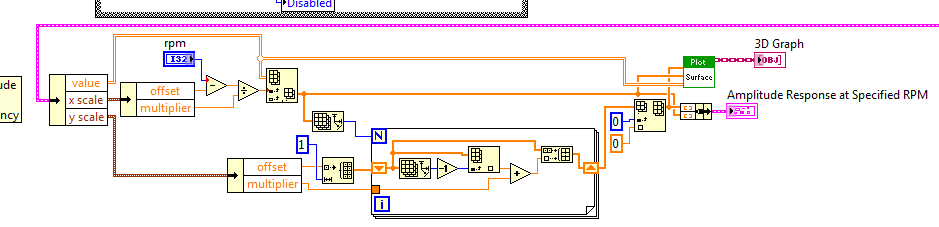
Map of spectral OATS (colormap) of a 3-d chart
Hello;
Sorry for my English
My problem is how to trace a colormap (OATS spectral map .vi "sound and vibration module output") in graphical 3D surface my entries are signal scaling and the velocity profile and my output is a colormap value I can trace this in the 2D color palette
graphic with no problems but can't do 3D please I need help
BROUTCHOUX,
If you want to analyze the color of VI map data in a vector, vector X Y and Z matrix, you can use it with this type of track. As the color of VI map is written, it displays a 2D path where the third dimension is the color spectrum.
This example of community pulls the data for you, you would just connect to the spectral curve:
https://decibel.NI.com/content/docs/doc-24070
Like this:
-
How to calculate time filter ADC for USB-4431
I do a continuous measurement of the aregenerative AOAI. I need to compensate for the delay of ADC filter both the delay in output filter
The delay of output filter seems to be well documented in the manual NI DSA (link below)
http://www.NI.com/PDF/manuals/371235g.PDF
ADC filter delay is more difficult to find manual DSA says look at 443 x specifications.
The specification gives a delay of "nominal" of 38 samples ADC filter. I can't find a more precise definition (link below)
http://www.NI.com/PDF/manuals/372485c.PDF
I'm using labview 2010, on XP
attached is a sample vi. He uses a loop of producer consumer example that I modified
I could manually find the total different sampling frequency offset, but I would have preferred a way to calculate it.
Thank you
Timm C.
When you say 'calculate', mean you automatically measure, calculated by the formula, or search in the table?
It's a good idea to measure the total delay (DAC + CDA + other) of the measuring device to each sampling frequency of measurement used in your application. Best practice is to run this measure whenever the system is powered up or rebooted.
We recommend that you use VI provided by Sound and Vibration Toolkit to measure the delay and additional delays that may be introduced by the device under test:
\vi.lib\addons\Sound and Vibration\svt_Calibration\SVL measure Propagation delay .vi (DAQmx) If you don't have a SVT/SVMS, you can recreate the measure of delay with LabVIEW complete edition features.
Start to synchronize your AO and AI using the same implementation used in your application of measure.
Use a test as a monopulse Gaussian signal and search for relaxation both the signal generated as well as the acquired signal. The difference between the locations of trigger is the delay.
Or use a test signal as MLS or Chirp, and cross-correlation model to measure the delay.
But I like to use the VI SVT ;-)
-
Dear experts OR,.
I have a PCMCIA DAQ6062E card OR makes the ADC and DAC for the collection of data in my lab. However, I'm confused with the bits of resolution posted on the Web page or http://sine.ni.com/nips/cds/view/p/lang/en/nid/11918. On the description on the right of the 6062E map image, it says: "..., 16-bit analog input,..." However, if you click Open the book loads tab below, under the heading "Analog Input", it says: "resolution...". 12-bit". Even for specifications under the "Analog Output" section: 12 bit. Dear Sir or Madam, I think I'm confused. NOR-6062E DAQ has a 12 bit or 16 bit ADC?
Sincerely,
Fuh
Dear Seth,
I thank very you much for the clarification.
Sincerely,
Fuh
-
using several of the ADC (ad7476a) via SPI
Hello:
I BF537-EZkit and AD7476A-GERD and I set to work using the project "SPI and UART.
But in my project, I have to AD7576A several... How to configure the SPI to do this?
I used the "analog s in reading" loop inside the moment (who writes via UART), but he reads the ADC too slowly for the reading of the AC...
What is the correct way to do it? The UART is useless I use it just to see the values read by the ADC...
Thanks in advance,
Antonio Freitas Verissimo
Hello
To control the operation of the multiplexer, you can use a digital output of the Blackfin. You can use the PPI on the Blackfin to do. You will be able to control in LabVIEW with functions at Black fins that have been added to the palette for LabVIEW.
If you are not familiar with LabVIEW, you can learn here:
http://digital.NI.com/public.nsf/allkb/7D5F60ADBFD9CDC2862572BA005DD96A?OpenDocument
Besides, the exercises provided with the EZkit should help ( http://zone.ni.com/devzone/cda/tut/p/id/6949 ).Best regards
-
* See Appendix VI
port 4 (can forget the other ports) the graph of the histogram, it produces a graph of a table 1 d of a cluster of 2 elements. I want a graph of just a cluster of 2 elements, I did this for the rest of the project and not the table 1 d. any ideas?
In generate_hist_Generic.vi, you HIstogram.vi inside a loop, and you send the output through a tunnel of indexation, which translates into a table.
Because your vi (hist.vi) call passes an array of single element, the loop will iterate that only once, and the result will be an array single element.
You can use the table to Index to get the item. See attachment.
-
The power spectral density function counts inaccurate amplitude caused by the window function?
I'm new to this forum, so please let me know if this would correspond better to a different discussion forum.
Here's the question:
I would like to know if the power spectral density function ("FFT PSD for 1 Channel.vi") automatically compensates for the loss of the amplitude of entry caused by the window function. In other words, is a specific window correction factor applied within the PSD vi or do I apply manually?
Details of the background:
I tried to answer the question myself by generating a sine wave sampling, it as it is periodic in record time (i.e. 0 to each end of recording time). The frequency of the sine wave was such that the frequency would exactly correspond to a spectral line in the PSD. Then I generated the PSD of the sine wave twice: once using a Hanning window and once using a rectangular window (not on average in both cases). The rectangular extent of the PSD with windows to the frequency of the sine wave is 1.5 times the size of the PSD with a Hanning window applied.
The experience above indicated to me that a manual setting of the PSD output for the function of window was necessary, however, I repeated the above experiment using random vibration data and does not clear 1.5 x factor. I have also been informed by his colleagues that the PSD should set for the window function.
Thank you for your comments.
Spectral leakage. When you use a finished sample data from the spectrum resulting is the convolution of the spectrum of the signal as if it extended indefinitely in time with the spectrum of the window. Even if you do not use a window function, you actually have a rectangular window the same width as the sample size.
Draw out of the VI PSD with all style of trace to show points to the data points. Turn off Auto scale on the X axis, and expand the graph around your pic. Look at the results of different windows. In any case, there are several values non-null. With actual sampled data of limited duration, you will never get the idealized line spectrum.
If summarize you the output spectral value remains close to 3.2 for all windows.
Lynn
-
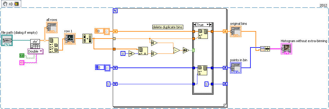
Hello
I'm trying to generate a histogram of data from the oscilloscope. The data is a kind of noise. The problem is that the data is already bin - ed the oscilloscope and the binning is not constant. If I can use a histogram, the output will be largely dependent on the binning in the histogram. If I have for example the binning set wrong, I couldn't see some vertices or I could see a fall somewhere, just because a histogram bin counts 2 buckets of the oscilloscope and the other a 3 bins of the oscilloscope. Later, I get a Gaussian of the histogram.
My question: is it possible to do a histogram on the data I receive directly from the oscilloscope, without attributing bins? And I can still fit my Gaussian data?
Best regards
Lorenz
Edit: So I want to essentially circumvent the problem of interference between the 2 offering.
I would now like to accumulate all the data points have the same value and get a distribution from that.
OK, now I understand! I would call it a histogram without binning-extra:
-
What is the best way to generate the density curve for example spectral dBuV / 200 Hz?
There are large screws for PSD, but this is an easy way to create a field of spectral density with units dBuV/200 Hz?
Hey steveMAX,
If you have equipment that can acquire these tensions, then it should be too difficult. You can use the Express VI spectral measures to produce the data. This will automatically give you the output in dB. You can then resize the axis on the graphical indicator you create so that you can display the correct data and label the axis correctly.
Kind regards
Chris
Maybe you are looking for
-
iOS 9.3.1 App crash "active Zoom.
I made the mistake of updating my mini Ipad with ios 9.3. Now, when I'm in an application (it doesn't seem to matter what type - games, weather, news) there all of a sudden freezes the screen is blank and I get the 'active zoom' appear square before
-
Images of the particular load-only error of the site, other computers can see perfectly well site.
I am trying to display fabric.com. Initially, I looked the site very well, then I have connected to a WiFi with bad service and none of the pictures showed on this site and others. Now whenever I discovered the site, photos do not come to the top. I'
-
helps connect to the NIST NTP server on port 123
I can get time NIST in day format using the rt_nist_date_time.llb example, posted on ni.com, but I can't connect to NIST NTP format time data using the port 123. I freely admit to be over my head with this stuff and have spent a large part of this h
-
Free CD for XP Service Pact 2 theres not listed for the country!
Didn't try to download CD & theres no registration for USA. Cannot get past this entry box.
-
Hi all I have an anyconnect configured in an ASA, is is authenticating with an ACS, we do not have more than 8 users with this vpn, I would like to know how I can configure the anyconnect to also do a validation of the local user if the ACS settles.