Speed CompactDAQ OR 9401 DIO PWM
I think the use of a DIO NI9401 to generate 4 PWM. The module can do 100 ns (10 MHz). If I want to generate 4 PWM, each 1 MHz with a CompactDAQ, I should be ok, right? I guess I can do that, because the NI9401 is a correlation module, and I should be able to give the news of PWM waveform for module and it allows to generate the PWM without using software to turn the line. CompactDAQ not being real time as the CompactRIO, I'm afraid that he can't have enough speed. Comments?
jyang72211,
My understanding of your project, you should be able to do. Don't forget not to a rate of update of the full cycle taking 1 MHz and 10 MHz, you can change state 10 times per cycle (duty 10 cycles). Specifications listed on our site for the 9401, that it seems the maximum clock frequency of 10 MHz, which should be fine.
One thing to note is that you should probably use the regeneration for continuous output data, I doubt that you will be able to broadcast four waveforms by usb/ethernet to 10 MHz. However, it is possible to get a glitch when you start trying to write a new waveform in the guy when you implement the regeneration of your project. This could be a problem for some apps and not even noticed by others.
Tags: NI Hardware
Similar Questions
-
Hi guys!
I'm working on a project where I want to control a motor dc with VirtualBench and LabView.
I have the engine connected to a H-Bridge motor, so I need to send 3 digital signals from the DIO VirtualBench to H-bridge.
With respect to management, I figured out, but now I need help to get a PWM signal to one of the DIO pins.
I can generate a PWM of the FGEN but do not know how to export to a DIO PIN.
I can also generate a PWM with the Express-> entry-> function Generate signal in Labview. But I get an error when you try to write this signal to pin.
Or is there a way smarter or easier?
Help, please!
/ Christian
The digital i/o pins are supported as the SPI, I2C, static DIO (timed by the software) and exports of MSO Trigger or FGEN signals start. There isn't any feature PWM/meter.
It is not a way to generate a PWM signal real on the DIO pins, nor can you give a digital waveform to dig write. From the FGEN might be your best option here.
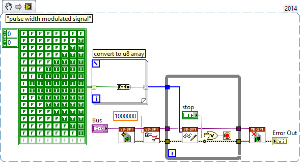
Another possibility might be to use (ab) the functionality of mastering of SPI. The following VI generates a modulated signal of pulse on dig/1 (MOSI) width. It will also generate signals on dig/0 (CLK) and dig/3 (CS), which may not be desirable, and you will have "gaps" between each call to read write of SPI.
-
Voltage offset problems with the NO-9401 for PWM signal output
I try to create a 20 kHz PWM signal to drive a motor control circuit uses the NI 9401 module in the chassis OR cRIO-9073. Generating the PWM signal works. For some reason, changes in shift of power as the market factor is increased. It is less effective for the engine, as you can imagine.
The code I am using is the finder of the example, for the generation of PWM on an FPGA and is attached.
I thought that it worked before but may have used the the NOR-9505 rather PWM output to test my circuit. It would be unreasonable for me to do this as a permanent solution.
The problem can be summed up as: with an increase in the liability of the cycle the voltage line (offset) movement of the output signal in the negative (according to ADGE) Basic or down. The Vpp signal is correct and does not change. Against ticks from 0 to the maximum of 2000 ticks (duty cycle IN), the offset voltage shift is such that 100% the level of full voltage is 0V.
Any ideas as to why this offset voltage shift that happens?
Do not be dismayed, I worked on the problem. There was a connection problem - I thought I was logged in as reference Earth, but it has not been properly clipped.
-
Error-200022 OR-9401 DIO and task of the clock
Could someone please watch this VI and explain how I can fix getting the reserved error-200022 the task? The VI implements a clock task to monitor the engine steps and another to monitor the engine on the NOR-9401 entries. There must be a way to make the two tasks together I hope somehow without this reserve error appears. If this is not the case, how would have managed to do this differently?
Thank you.
-When I ran the VI I 200463 error. I could solve that question changing in the DAQmx creating channel line group to a single channel for each line of entry.
-Then, I ran the VI and I have error-200022. So as a workaround, you must change the meter (ctr0) If you use 4, 5, 6 and 7 in the form of digital lines. However, if you make this change you will get error-201133. To resolve this problem, click the link below:
Concerning
-
Generate a single pulse on several channels of an external trigger high-speed DIO
Hello
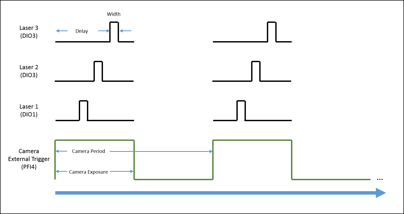
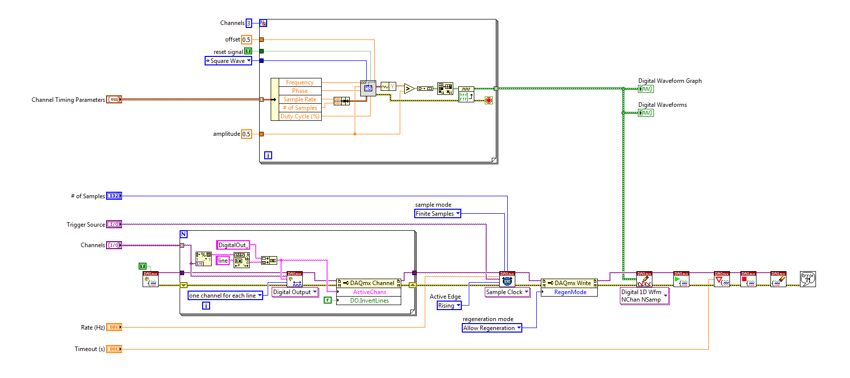
I'm trying to implement a system using a PCIe-6535 b connected to a high speed of SMB-2163 DIO. The system must be configured to work with a camera send a trigger (at the beginning of each show) to the PFI4 which in turn sends a single pulse on three digital output channels to lasers. Each output has its own specific deadline and the width. There is no counter on the SMB-2163, so I think I need to use Pulse Width Modulation (PWM). I saw this example and adapted to my system:
https://decibel.NI.com/content/docs/doc-8010
However, when the source to enter the DAQmx VI of sample clock is set to PFI4 (instead of the on-board clock) to receive input from the camera, changes in behaviour. The rate of sampling in the sample clock VI is ignored, and each element of the digital waveform is triggered. I need the sequence to complete each after trigger.
I am attaching a quick diagram of the sequence. Any suggestions on how I can get this kind of events triggered? (With the help of LabVIEW 2013)
Thank you
Mike
PLATES
The external signal must be configured as a trigger for digital startup rather than the sample clock. I do not think the 6535 redeclenchables supports digital output, so you don't have to restart the task after receipt of each trigger (something like this, however you can improve performance by committing to the task by using the task of control DAQmx before entering the loop).
Best regards
-
cDAQ-9178 & NI 9401 - ASM: incremental Rotary encoder works is not beyond a certain frequency
I use a chassis with a NI 9401 DIO module 9178 cDAQ. I'm trying to convert the output of a rotary incremental encoder ASM (in radians) to rpm.
Sensing head (PMIS4-20-50-240kHz-TTL24V-Z0-2M-S)
Snap ring (PMIR7N-20-50-M-20)
The encoder outputs 2500 pulses per rev (output 5V TTL). The maximum speed which will see the encoder is 2800 rpm, which is equivalent to 2800 RPM * 2500ppr/60 = 116,667.67 Hz in terms of frequency.
Since the NI 9401 of the operations specifications:
Maximum of the input signal switching frequency by the number of input channels, by channel
8 input channels... 9 MHz
4 input channels... 16 MHz
2 input channels... 30 MHzI use only 1 channel, so I'm assuming that the 9401 should be more than capable of handling the 116kHz which the ASM encoder is spit.
Everything works fine until about 2100 RPM (~ 87, 500 Hz) but then I begin to see a drop in rpm, followed by a flattened behavior, then a slight increase. But never more than 2100 RPM. Our test unit is inspected for other reasons at the moment so I can't produce a plot of the behavior (I can reupload later). I think this must be a matter of aliasing with the meter or something of the sort. I have a digital filter set in place with a minimum of 4.0E pulse width - 6. It is two times smaller than the width of minimum pulse at a frequency of 116kHz (0.0000085714). I don't think this should have an impact on the calculation.
Any suggestions? This value of RPM is essential to our application.
Thanks in advance,
-MB
brown_ktr wrote:
I have a digital filter set in place with a minimum of 4.0E pulse width - 6. It is two times smaller than the width of minimum pulse at a frequency of 116kHz (0.0000085714). I don't think this should have an impact on the calculation.
A 116 kHz frequency, the period is ~8.57 us, but the pulse width half duty cycle of 50%. Ascent/descent time factor, and it is quite possible that 4 US is too long for your encoder signal.
The shape of this graph supports this theory, if we consider that there is variation in the exact pulse of each encoder pulse width. The shortest pulse is ignored when the filter starts to kick in, and the speed of ROTATION increases pulses longer and longer are ignored then as well.
Try to decrease the minimum pulse of digital filter (US 2 or even 1 US) width and see how it goes.
Best regards
-
synchronize NI 9514 with NI 9401 for digital output
Hello
I need to write code to trigger a laser for a PIV system. I use the NI 9514 with training AKD to order a servo. I need to send a + 5V signal to trigger the laser at an angle of rotation of the motor (this is repeated for each turn of the rotor) specific. I also have the NI 9401 DIO. Any idea/example of how to proceed will be much appreciate. I use the scan to the NI 9514 mode, my system is a CRio-9022 with 9114 chassis.
Thank you very much!
According to me, that the example to compare periodic Position is what you are looking for. The description States "shows how to use the output of compare position to generate an output signal to a regular period.
You can find it by going to help > find examples > Input and Output material > Motion Control > NI SoftMotion > properties and methods > advanced.
-
Using the C-series SCTL DIO module with slower than the top level [FPGA] clock
Hey all,.
I'm running online research on a problem that I have a lot of success.
I have a chassis with integrated FPGA, top-level 9030 clock 40 MHz. I have a NOR-9401 DIO C Series module plugged and the value that will be managed by the FPGA target. I need to count some linear encoders to exactly 10 MHz, no more, no less. They are periods and gives a result of such kind that if I oversample or underestimate, I get garbage.
If I create a SCTL and assign a source of synchronization derived from 10 MHz, I get an error code generation who:
"Node read e/s for DIO3 FPGA is used in a clock domain that it does not support. Areas of clock supported include: the clock of higher and clocks that have a rate that is a multiple of 40 MHz, for example 40 MHz, 80 MHz, 120 MHz and so on. »
I tried several ways to work around this problem; First I tried just using a while loop with a loop set to 4 is ticking timer, but it then takes 9 clock cycles to perform the count for a reason any (although this code may compile in the SCTL without any problem). I then tried to use the SCTL with a constant of 'true' AS a hack for a 'timed sequence' framework-related, and that certainly has not worked.
Are there any strategies or techniques, or settings somewhere to work around this limitation on the AID I need to taste exactly 10 MHz? I'd like to do this quickly in the software and get this rolling as soon as POSSIBLE.
An image of the relevant section of the code is attached, I'm happy to provide you more things on request.
Thank you very much!
Maia Bageant
Thanks for the reply! The problem ended up being a hardware problem based on how coders were connected. Now that I've fixed it, they're perfectly happy are oversampled.
I guess my question is always legitimate to other applications, but not necessary for encoders a.
-
xw6400 & xw6600 secret fan: quiet workstations
My best info on tweaking of the workstations xw6400 and xw6600 to run more quietly without increasing the internal temperature when measured with specific utilities has been noticed (and also BIOS) in the xw6600 is attached.
I mention the speed reducers of Noctua fan resistance, 4-wire, and those that work very well for fans of memory and the chipset. Also, I swapped the xw6600 parts in the xw6400 (fans and broadcasters) the advantage of the most recent HP engineering.
Overall my versions optimized for these workstations run as quiet or more calmly than the Z620, at little cost. The 4 speed reducers son PWM-preserving you seek are more easily purchased through a pack of 3 of Noctua, found if you google NA-SRC7. Use one on your memory fan and the other on your chipset fan and fan of memory if you have a xw6600. Other methods of note are more than a project, but I recommend doing at least the addition of the adapter.
See attachment:
A little added information about fan of little chipset of the xw6600 who run very fast in the xw6600 and is slow. The Northbridge chipset on the xw6400 has only a radiator... not a fan of any other movement of air attracted on the radiator by the memory fan. I saw no deficit of cooling by dropping this 3745 up to 2752 chipset fan speed. About 1 k rpm speed reduction significantly reduced the total noise of work stations, however. The same concept goes for why add a reducer of Noctua 4 son LNA to fan fan speed memory of the xw6600... lower the speed and noise of the fan with no measurable in time of the memory increase, while maintaining the ability of the motherboard to increase the speed of the fan automatically if necessary.
HP uses the PWM controlled EFB0412HD Delta 40x40x20mm which has one - modifier 7R49 (on the label). These modifiers to identify fine details of the fan, and for is this it indicates that control PWM has been added, the wires are short and white connect type conventional PWM.
If you never had to get only a replacement fan 3 son he will run to 12VDC full speed, with no gas HP PWM applied. Here is the RPM:
3-wire (son PWM is unplugged or 3-wire fan): 7500-8500 (measured on several xw6600s)
No adapter and with reference HP PWM applied Butterfly: 3745 (average)
"Adapter 4 son Noctua LNA more reference HP gas: 3101"
"Adapter 4 son Noctua ULNA more reference HP gas: 2752"
Noctua ULNA 4-wire adapters are difficult to get, but at least add in adapters Noctua ULNA NA-RC7 4 wires on your xw6600 fan memory and chipset fan. Those who are easy to find in a 3-pack by searching for "NA-SRC7.
Attached are the specs of the Delta with the version HD of this fan 12VDC highlighted and a pic of the fan with this modifier code on its label.
-
What is a digital output (DO) good for?
Actually, I wanted to use the outputs digital to move from a 24 VDC circuit (to turn on/off other devices etc.).
But the current output outputs digital is so low that I have even impossible to pass an opto-coupler (opto isolator).
That's why I wonder you use outputs digital for if you cannot use them to change anything?
Of course, I can create a circuit MOSFETS or transistors to switch 24VDC power with the TTL 5V digital output signal. But I guess that most of you do not :-)
And of course, I know that I can buy OR relay modules/cards. In fact, I have many digital outputs available and do not want to buy new modules/cards.
Now, I can test and actually I get 10mA @ 5V on a digital output of NI 9401 (DIO), using the digital output to pass an opto-Coupler.
It seems that the information contained in the data sheet are supposed to mean something else...
-
At the same time entered into a local variable of a digital control while maintaining control.
Hello world
I'm quite new to Labview please bear with my lack of technical terms. I also want to apologize in advance if this topic has already been discussed somewhere in the forum.
I'll try to be as brief as possible - I will use Labview for controlling the speed of a DC by PWM motor and want to simultaneously have 1.) control button which allows me to vary the PWM (0-255), and 2.) be able to 'fix' the value of the command using the indexed values.
To better illustrate this point of view please the VI attached. When you run the code what I can do is change the value of the control by using the indexed values. So going back to my question - what changes should I make to the code in order to have the choice of using 1.) (and 2.) at the same time?
Any help would be greatly appreciated!
After extensive research on the structures of the event and property nodes, I finally found a solution.
Is attached the working version of a button control that can be further manipulated by a secondary control, but still maintain it's own control capabilities (IE not the substitution or the line of the error stream)
I hope that someone in the future will find this useful!
-
I can measure the speed of the NI 9401 fan & cRIO 9075 under Scan Interface?
Hello
I am currently using OR 9401 & cRIO 9075 to develop a project, which is to control the CPU fans.
Since I have to communicate with other instruments by serial port, while I have a NI 9870 module to implement the instrument control.
I finished the part of control instrument under scan mode and would like to add the function of the fan speed reading.
Now, I wonder if there is a problem when I choose the Scan Interface to deverlop the program.
I found the following tutorial, he uses the FPGA interface to impement the acquisition of control and PWM frequency.
http://www.NI.com/white-paper/3230/en/
So if the function of the fan control only developed under an FPGA interface, I have to rewrite the control instrument part, seems to be a bit complicated...
You can use the hybrid mode.
http://digital.NI.com/public.nsf/allkb/0DB7FEF37C26AF85862575C400531690
-
I have a 9401 on a chassis 9188 module. What I want to do, is to have 3 DI, 1 and 1 PWM.
I thought I could put the DI 3 on channels 0,1,2. Output channel on 6 and a PWM using a digital channel 7 (-1). In this way, that they would be grouped with 1 4 input channels and the last 4 production by the manual.
The problem is I get a 201133 error that says that the device can be configured for input or output due to another task or directions when I try to run everything in the same vi. I can make the DI and DO tasks with no problem OR the PWM task without problem. I tried to book the tasks with the DAQmx control task VI as the suggested error, but not luck.
Is it possible to do all this on the 9401 at the same time?
Bryan
You won't be able to use 1 DI, 1, and up to 4 meter which are material tasks timed at the same time when you use a 9188: http://digital.ni.com/public.nsf/allkb/5E0B829E50ADE1BC86257AC50062B2D2?OpenDocument
In addition, you will need to make sure that you book the tasks to avoid the error of 201133 with the 9401: http://digital.ni.com/public.nsf/allkb/0495B7D5E2345DF386257730007EFD17
-Mike
-
Problem setting up an encoder input and PWM output tasks on CompactDAQ
I use a chassis with a modules 9474 cDAQ-9174 and 9411. I do not think it is important, but they are the cRIO-XXXX modules NOR old provided with a test configuration that has been distributed to early adopters. I use DAQmx tasks in an application (C libraries) to read (angular position) quadrature encoder and drive a motor directly with PWM current (pulse output). For various other needs, my tasks Setup is as follows:
[DAQmx] MajorVersion = 9
MinorVersion = 2
[DAQmxChannel venture 9411 wheel entry/AngularPosition]
CI. AngEncoder.PulsesPerRev = 500
CI. AngEncoder.InitialAngle = 0
CI. Encoder.ZIndexVal = 0
CI. Encoder.ZIndexPhase = a Low high B
CI. Encoder.ZIndexEnable = 0
ChanType = input meter
CI. MeasType = Position: angular encoder
CI. AngEncoder.Units = ticks
PhysicalChanName = cDAQ1Mod2/ctr2
CI. Encoder.DecodingType = X 4
[DAQmxChannel venture 9474 PWM output/PulseOutput]
CO. LTD.. Pulse.IdleState = low
ChanType = output meter
CO. LTD.. OutputType = Pulse:
CO. LTD.. Pulse.HighTime = 5.0000000000000004E - 006
CO. LTD.. Pulse.LowTime = 5.0000000000000002E - 005
CO. LTD.. Pulse.Time.InitialDelay = 0
CO. LTD.. Pulse.Time.Units = seconds
PhysicalChanName = cDAQ1Mod1/ctr3
[DAQmxTask venture 9411 wheel entry]
Channels = venture 9411 wheel input/AngularPosition
SampQuant.SampMode = continuous samples
SampClk.ActiveEdge = Rising
SampQuant.SampPerChan = 100000
SampClk.Rate = 100000
SampTimingType = sample clock
SampClk.src=/cDAQ1/100kHzTimebase
[DAQmxTask venture 9474 PWM output]
Channels = venture 9474, output PWM/PulseOutput
SampQuant.SampMode = continuous samples
SampQuant.SampPerChan = 100000
SampTimingType = implied
RegenMode = allow regeneration
[DAQmxCDAQChassis cDAQ1
] ProductType = cDAQ-9174
DevSerialNum = 0x18B3EC0
[DAQmxCDAQModule cDAQ1Mod1]
ProductType = NOR 9474
DevSerialNum = 0xDEDF40
CompactDAQ.ChassisDevName = cDAQ1
CompactDAQ.SlotNum = 1
[DAQmxCDAQModule cDAQ1Mod2]
ProductType = NOR 9411
DevSerialNum = 0xDEDB24
CompactDAQ.ChassisDevName = cDAQ1
CompactDAQ.SlotNum = 2
Each task works fine on its own (i.e. without the other). The problem is that if I start the task of the encoder first and then the task PWM, the latter causes an error:
Error-89137 occurred to the DAQ Assistant
Possible reasons:
Specified route can not be satisfied, because it requires resources that are currently in use by another route.Source device: cDAQ1
Point source:
80MHzTimebase
Destination device: cDAQ1
Destination
Terminal: Ctr3SourceNeed for resources in use by Source
Feature: cDAQ1
Terminal of source: 100kHzTimebase
Destination
Feature: cDAQ1
Destination terminal: Ctr2SampleClockThe task name: _unnamedTask<61>
I don't know why this is, but if I start the PWM task first, and then the task of the encoder, it also works. I should also mention that initially I was using counter 0 encoder, which caused a shift in the 100kHzTimebase to Ctr0SampleClock, which, according to the ways of device 9411, is not supported. Yet it worked (in itself). I wonder if this is happening under the hood isn't quite what is shown.
What is exactly the conflict and what can do to avoid it? The reasons for having to use specific modes and the settings (for example, the 'continuous samples' with 100kHzTimebase clock) are rooted in various performance and requirements of optimization that were created in a previous version of our software, so I prefer not to take a completely different path, if some small changes would lead us to correct the problem.
I appreciate your help.
Kamen
Hi Kamen,
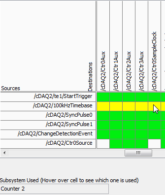
The time base of 100 kHz is not a direct route to the counter sample clocks, the device actually uses one of the other counters to complete the road (the routing table is a little misleading here because it shows 2 meter that one always doing road - in fact it will be any available counter):
So in your case, when you start the task of the encoder, it uses one of the other available counters to complete the configured road (100 kHz to ctr2 sample clock timebase). Of course, she chose meter 3.
Possible workarounds (looks like you have already found one yourself):
1 start the PWM before the task of the encoder task - if the task PWM starts first the counter is already booked and the task of the encoder would choose another available counter to complete its road.
2. explicitly reserve the PWM task before you begin the task of the encoder (if you need to start the task of the encoder first).
3. use cDAQ1/_freqout to generate the clock sample 100 kHz signal and use this instead of routing to the time base of 100 kHz to the counter sample clock.
Change autour counters should also work, but I'm not 100% sure how the unit selects which counter to use for routing (I don't expect change in the future, but if it's not explicitly spec'ed somewhere so I wouldn't take my chances)-if it were me, I would choose one of the other options above.
Best regards
-
phase shifted PWM with Ni 9401 and Crio
Hello
Do you have an idea of pwm shifted 180 degrees?
(duty cycle frequency and variable difficulty)
I tried a design, but it seems in the graphics design works on the realtime.vi but it does not work with the fpga.
Graphic output pwm FPGA are distinguished by the real time as you can see in the pictures.
On the other hand, VI Fpga produce two pwm, as seen in the oscilloscope when the fpga VI runs.
However, there is no phase shift between the PWM waves.
It is a part of my thesis, but I'm stuck in this problem, so I need assistance on your part.Thank you.
Best regards;
My hardware:
cRIO-9024 and cRIO-9118 chassis
NOR-9223, 9263 - nor, nor-9401, or-9474
two nor-9225 and nor-9227
Hi Maurice
Thank you for your help.
Yes I want to that they will be moved with the right variable and 10 kHz. I put 49% maximum duty.
I put the output into the same output block.
Square wave generator does not accept 'loop' while.
I have attached a simple FPGA project file. Could you please tell me what is my fault?
The resulting Pwm frequency is 10 kHz, the only problem is always the shifters.
So, I always need assistance.
Maybe you are looking for
-
not even sure how to ask the question... I have 2 external hard drives connected to my iMac, and 2 external hard drives connected to my mac mini... use an external hard drive to backup to another... it's 4 power supplies, 4 candles, 4 separate units.
-
Where can I buy a phone in the United States?
There is no information on the Web site on the search for a phone of a person living in the United States. The United States are not yet in the drop-down list and I went to Best Buy and a few other places when it may be available and they said they h
-
How can I disable my notice of permission
can u help
-
I can't hear any sound in my headset when I plug in my laptop which has Vista SP2 installed.
I can't hear any sound in my headset when I plug in my laptop which has Vista SP2 installed. While my speakers work well, I cannot hear any sound in my headphones every time that I plug them in. And whenever I take off the helmet, I can hear clearly.
-
Cannot find files after deleting one our user accounts.
Original title: help! Accounts deleted and made new and delicate issue, I know! But, I will be greatly grateful to the person who answers this! I want to get the files and images and not the account I had before. Anyway I could do? Oh, and I can't pu