synchronization mx-daq-dio HS
I would like to synchronize the nine 6123 cards (100 kHz analog) with six 6561 cards (LVDS 2 MHz). Correct me if I'm wrong, that the correct technique is to use meters. Use one count 6123 to generate a pulse of 100 kHz'd sync analog acquisition. Then set up a second 6123 meter as continuous trigger (20 - Pulse), trigger some of counter1 counter2, which gives an impulse of 2 MHz clock had analog acquisition. Then set TClk of LVDS to trigger 6123 counter2. Hey presto, all channels are overall sync.
Writing down is easy, but write the code a bit more complicated. If applications engineers or congratulations looking for members of the community have achieved such a feat, send the example code, it would be much appreciated.
Hi all
I just wanted to post the summary:
In order to synchronize, you must share a sample or reference clock. With the HSDIO as the master, you cannot share it except using the ClkOut Smb, impossible to write trigger lines connection in in a way that can receive the S series.
Using the S series as the master, you can easily generate a 2 MHz clock signal using a task of the meter output. This signal must be routed to the HSDIO device. This is only possible with the help of an external connection (ClkIn smb connector or line Strobe), since the card cannot be written in PXI_Trig7 or line STAR PXI S series (HSDIO device can accept signals of sample ClkIn STAR PXI and Strobe clock; it can accept clocks of reference on ClkIn, PXI_CLK10 and Trig7).
See the attached example, I created to do exactly this.
I realize that using external connections may not be the preferred solution. Another idea we had, it is possible to use a build task in conjunction with script on a device HSDIO markers in order to effectively generate the 2 MHz clock that can be shared on a line of PXI_Trig. This can be broken down on the S series to the sample clock cards HAVE.
Kind regards
James Hillman
SR: 721280
Tags: NI Software
Similar Questions
-
Card NI DAQ for SinCos encoder?
We have a RON285 heidenhain encoder that uses signaliing 1Vpp for "infinite precision". Essentially, it generates two differentials Sin / Cos signals angle and the phase between them allows you to achieve extreme precision for the angle of the encoder. You must always send two signals with a comparator hysteresis to essentially convert the signal quadrature encoder and count the pulses. Calculation of phase angle gives you the fractional precision.
(1) no matter who never used a capture card of data OR to read in the first tensions and make the calculations necessary to convert the singal SinCos until a high precision angle? If so, you are ready to share the code?
(2) make the SinCos--> Quadrature conversion on the card itself by splitting off the two singals SinCos in two other channels and specify these two channels is coded quadrature singals or do have external hardware do the comparator + hysteresis before it captures in the map?
P. S.
I just found this piece of hardware that does exactly what I described in #2 above, I get this same functionality using just the DAQ itself card? http://www.motrona.com/SinCos.html
The pointed inline Heidenhain WHAT JB interpolator is exactly the kind of thing I used other suppliers. Yes, you can introduce digital quadrature channels in a meter and other synchronization maps DAQ in a PXI chassis. 9 kHz in quadrature frequency is easily manipulated by the jury.
Setting the "pulses per rev' to 360000 and choosing degrees for units should cause the task to do the math for you, for example, when you call DAQmx Read values should already be adjusted to degrees. Personally, I do always some reason check this scaling value to make sure that there is not a factor of 4 gap because of the differing terminology between encoder and DAQmx tasks sheets.
As to limit yourself to the Tween 20 x, I tend to agree. If the Encoder error has been distributed randomly, I completely agree. But because much of it is probably more systematic than at random, there is a * chance * as some other fractional resolution might be useful. Probably a pretty small gain at best however. Unless it's quite similar cost & time probably, I wouldn't bother to > 20 x.
-Kevin P
-
Data acquisition and video acquisition
Hi all
I am a new user of Labview. I am trying to build a VI that synchronize acquisition DAQ voltage of one or more channels to an AVI video acquisition (IMAQ) (including a bayer encoding process), recorderd by a digital camera.
I built this VI which I attach.
The problem I have right now is that I am able to do a video and a signal, but the duration of the video is always different from the signal, I can read the time in the file LVM vector.
Could you please tell me how I can solve this problem?
Perhaps this question may seem easy, but. As a new user, I know very well how to use Labview in the most effective way.
Thank you all for your time.
Emanuele
Thank you very much, I am modifying the program, but I do not understand how you linked the son two error, I can't find the box you put just before the other 'error' box, please let me know hat it's and what is used.
Thank you very much four alos your patience.
Emanuele
-
Excerpts from continuous data acquisition
Hello
I want to make an acquisition of continuous data with a NEITHER-6133 @ 1ms per channel. The data must be stored on hard disk. At the same time, I want to take excerpts from acquisition to calculate different values. The acquisition of the extract must be triggert by an external digital trigger. Are there examples, which combine continuous data collection and collection excerpts?
Thank you very much.
Best regards
Michael
System
Windows 7
LabVIEW 2012
NOR-6133
Thanks to the support of NOR-Germany, I found a solution for me:
1.) continuous trigger switch
Connect 2) the trigger for the signal to a digital i/o
3.) synchronize AI and DIO
Excerpt 4.) the samples needed by the search within the digital waveform pattern
Result:
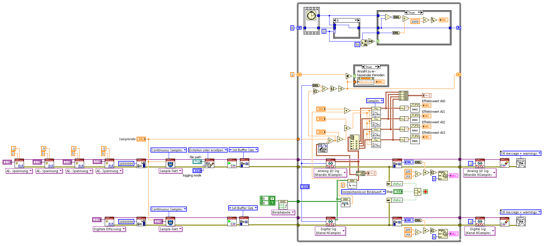
The example shows 4 IA channels Cup (tested on Win7, NI PCI-6115, 4 channels each 5. MECH / s) and calculation on extracts from each channel signal triggered parts.
-
Can we run a LabVIEW VI and downloaded at the same time on Arduino code map Arduino?
If we use LabVIEW to write data in series to an Arduino, can send us on the Arduino code before you run the VI so that the Arduino has something to do with the signals it receives from LabVIEW? Specifically, we want to use the digital IO pins to read into a signal on the Arduino (provided in series by LabVIEW) and do something with the signals as a LED lights up. Is that what most people do?
Our project includes a parking meter and we want to use the Arduino by itself, but first we want to simulate the code using some signals that we want to move through LabVIEW. Basically, the meter said the Arduino, if they are paid, and if there is five minutes or less remaining on time. Based on this information and data from a PING sensor, we will determine which exit to turn off (a flashing LED to different frequencies to designate two different messages).
Sorry if my question is not clear or if it is trivial; my partners and I are very new to LabVIEW and the Arduino, and we try to get this working soon.
The LabView VI Arduino library is designed to work with the Arduino as a USB DAQ/DIO.
This isn't really what you're after...
I don't really know how LabView would be useful in this project.
-
U8 NChan NSamp 2D DAQmx writing question: Digital
The help file says that for the "Digital 2D U8 NChan NSamp' vi, each row of U8s is a channel and each column is a sample. But each sample U8 get extended to 8 bits? If so, what bit is first (MSB or LSB)?
If this is not the case, how the U8 is sent to the material. Is the U8 a sample of port where each bit value corresponds to a line on a port? If it is this plan, so I guess if you had 3 lines in a channel, 5 bits of the U8 would be unused. I also assume that all lines in a channel would have to be on the same port.
I guess my confusion comes because I think a somewhat broad digital as channel, while the literature seems to indicate that a digital channel can be composed of several bits.
I don't have a DAQ DIO to confirm this, but I think the LSB of the U8 goes to port x 0 (D0), line up the MSB goes to port x line 7 (D7). So if you had 3 lines in a channel, 5 bits of the U8 would be ignored. Yes, all lines must be on the same port. If the polymorphic selection is U8, then you must have 8 rows on the same port. If the U16, two ports are concantenated to form 16 lines that correspond with the U16.
I too tend to think of a digital channel in one line. The terminology is confusing. They shouldn't mention the word of all channel. It should be ports and lines only, as port 0 line until the line port 0 7 0, then 1 line 0 port and so on.
The expression "each row of U8s is a channel", I think that this meant that only one channel is the 8 lines of a port. In other words, the channel is a port. I guess they use the channel because if you specify U16, a channel could be ports 0 and 1.
-
Alert about the NOOB - interface DIY to labview circuit suggestions?
Good afternoon everyone,
Long story short, I did not use labview in years and years and years. I wrote code built-in to most and c# and the design material since my days of recording data. As fate would have, I just become used by a very very large company that seems to have a love with Labview interest, so I will use to automate some tests and other whatnot. For everything that I have, it is clear how to go. I'm more concerned about how I could make interface labview for personalized, switches, relay, simple stuff like that stuff. Maybe just control and not proofreading.
So my question is, is there, and if so, what is it, a circuit interface that would allow me to plug and interface to a piece of custom circuitry. I'm guessing a series or USB or maybe even an interface chip FTDI or something would seem logical. I can do everthing beyond that, I don't want to go down rabbit hole if there is a proven simple circuit already out there. I know there are few interfaces (myDaq?), you can buy, but I'm hoping to find a way that I can't buy anything and I can just incorporate some little project that I do.
I googled around and have yet to find anything. A general topology is good, a schema is better, a diagram with code source (if necessary) is ideal.
So what you know? and thanks in advance.
What is and Arduino? They are cheap and once you have something doesn't work, you can load the bootstrapper Arduino Atmel virgins and incorperate into your design.
It is predefined code LabView as cominucates with an Arduino and use it as a simple Board DAQ/DIO. That is, it must always be teathered it do not program the Arduino to run stand alone.
https://decibel.NI.com/content/groups/LabVIEW-interface-for-Arduino
-
Can I synchronize list XCP DAQ with my analog input data data?
Hi all
"I use ' ECU M & C" for measurement of a computer data using the XCP DAQ list. "The data is read at the sampling frequency I put in ' MC DAQ initialize.vi. This works well.
I want to associate this data with my DAQmx device measures. Is it possible to synchronize the clocks of the sample (by RTSI?) in the same way, it would be with DAQmx CAN synchronize data?
Material: NO PCI-CAN/2 & OR PCI-6229.
Thanks for any input.
PJ
Hi PJ,.
Well, I think I understand now, I don't know why I DINA see this before. It is not possbile to do this with the ECU Measurement and Calibration Toolkit, sort of XCP DAQ, is not something that you are able to do.
Best regards
-
Synchronize PXI-8512/2 and DAQ, PXI-6220 CAN
Hello
I read some examples and other posts on the topic "sync", but I need more information.
I'm using a PXI-8512/2 with an older application, based on the API of frame. Several frames are transmitted and received periodically, and I need to enter a unique ID of arbitration which has a cycle of ~ 5 ms.
At the same time, I need a task of data acquisition (analog input) with a sampling frequency of 1000 Hz.
The challenge is, I need to have the same time base for the analog input and CAN.
As far as I understand, the timestamps CAN are created in the PXI-8512. The timestamp of the start of the DAQ tasks is based on the time of OS (Windows).
Transmission/reception CAN must be running still (to perpetuate the ECU), and the data acquisition task will be triggered manually.
I found the example '\nican\Frame - base with NI - DAQmx.llb\CAN Frame entry API DAQmx Input.vi'. It fits my needs? There is a comment saying: "the departure of AI uses the same sampling as CAN. What it means? The sampling frequency of my CAN is fundamentally different from DAQ. But I have to be able to associate each sample DAQ for a CAN of armature (same time base).
Thank you for any information helping to clarify.
Concerning
Hello
Sorry, I don't know why I thought you had an X-Series. There is also an example for the other series with the XNET driver:
Synchronize PXI - CAN with analog DAQmx of entry (using the PXI-Clk10) .vi
Kind regards
Heinz
-
Dear community,
I am trying to implement a background basket (software) PXI trigger on a chassis NI SMU-1082 with LabView 2015 (32-bit) running on an SMU-8135:
HS-DIO (SMU-6544) in slot 2,
-Acquisition of data (SMU-6363) into the Groove 4,
-Flex RIO (SMU-7962R + OR-6583) in the Groove 3.
The trigger schema is explained in the attached file ' LV-PXItrig-HSDIO-DAQ - overview.jpg ".
Scenario 1: written DAQ analog signal and sends signals trigger HS-DIO (software) through bottom of basket, after East of waveform of the complete signals to DAQ for acquisition.
Scenario 2: logical impulse on an external port HS-DIO triggers signals HS-DIO, after HS-DIO waveform is complete DAQ triggered for the acquisition of the ADC by the backplane.
In principle this breaks down to send a trigger of module A to B by PXI backplane. The SMU-1082 chassis has a bus trip with 8 lines (PXI_trigX, X = 0,..., 7) more a trigger in Star controlled the slot 2.
I've linked to implement a software trigger, but I can't access the refreshing resource and execution, see the attachment. Other ways of implementation including the DAQmx Terminal / routine disconnect Terminal have not worked for me either. I am aware about the connection of trigger using the node property VISA but I can't make a trigger.
Tips, comments or solutions are appreciated. Thank you!
For scenario 1, you want to trigger the HSDIO acquisition to begin as soon as the analog output DAQ starts? You can use
DAQmx Export Signalto send the trigger for the start of one of the lines from the Trig PXI backplane. Then, you need to configure your HSDIO acquisition to use a trigger digital beginning on the same line of trigger. Take a look at the example of the "Dynamic hardware generation start trigger" in the Finder of the example (help > find examples)For scenario 2, looks like you do a dynamic unit HSDIO generation when a digital trigger arrives on one of the PFI lines. Once the build is complete, you want to send a trigger for the DAQ hardware to begin sampling. If this is the case, you again use a trigger to start material in your task of NOR-HSDIO, as you did for scenario 1, but use external trig line as the source, rather than the bottom of basket. There is no case of material when the build is finished, but you can use a marker in script mode event instead. The example of the Generation with dynamic event marker' in the example Finder gives a good starting point for this type of operation. You'll want to set the output terminal for the event to be a line of backplane trig, and then tap the DAQmx to start on the same line trig trigger.
-
Synchronize two E-card with traditional DAQ series
Hello
I have a PCI-6052E and a PCI-6071E and I have a Matlab program that interacts with traditional hardware DAQ driver cards.
It is possible to synchronize the two cards use RTSI or something? If so, what should I do in matlab to achieve?
I'm a bit confused, because I don't know if this is only possible using DAQmx.
Thank you!
Hi zlyhere,
Using DAQmx would definitely be the best choice.
In terms of using C vs the Data Acquisition Toolbox for The MathWorks Inc. Matlab® Software, I would recommend the Toolbox for ease of use. The MathWorks develops the Toolbox, so they must have documents on how the maps can be synchronized.
If you find that you need more features, you can fall back to C. Documentation is available at
"" "" Start menu"all programs" National Instruments "NOR-DAQ" support textual Code ' using NOR-DAQmx C reference
MATLAB® is a registered trademark of The MathWorks, Inc.
See you soon!
-
Synchronization of several high at different frequencies of sampling DAQ cards.
I'm having sync problems 3 high DAQ cards with different sampling frequencies. I use 2 cards PXI-6259 nec 10,000s samples and 1 PXI-6221 Board to interface for my SCXI modules in 10 samples/second. The problem that I discovered is the time related with the waveforms of the NI PXI-6221. When I run the code on a development computer using virtual devices in MAX, it works as expected. When I run the same code on real hardware, the stopwatch turns approximately 25 X faster than normal. I enclose the code and the config that I use.
Any ideas?
Hi NGNN CAD.
First of all, let me say that your code is very nice!
The problem is that you are using the fast sample for the device that is supposed to be slow clock:
Even if you specify the rate as 10 Hz, the clock itself is still at 10 kHz (by specifying the right rate allows the DAQmx driver determine the size of buffer etc and don't actually change your external sample clock speed - however, it changes the rate of the simulated device).
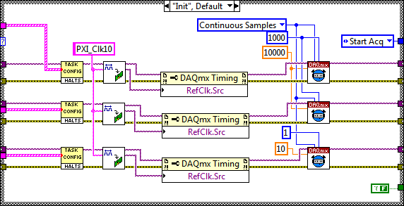
My recommendation to synchronize devices would use the built-in PLL and lock to the reference clock 10 MHz of your PXI chassis. Your devices would always share a trigger to start, but each would generate its own sample clock based on its time base that is locked to 10 MHz reference.
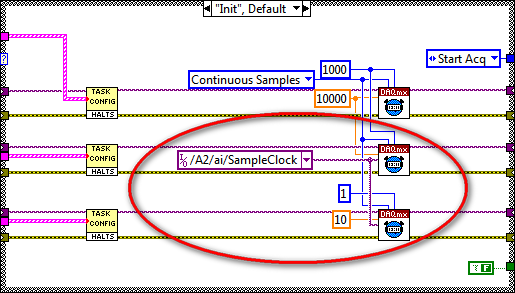
The code should look like this:
I hope this helps, let me know if you have any questions!
Best regards
-
Synchronize subvis SMU and DAQ
Hello
I am trying to build a VI in which a DAQ 6368 outputs an arbitrary function, and a bed SMU4141 the trace underway, each sample to ~ 10 kHz. I want that the acquisition of data to read it's own output voltage at the same time. In this way, I get a trace of tension of the acquisition, data and track being SMU allowing me to make curves of IV. I want the voltage and current traces having the same number of data points and on/off switch at the same time.
Now I think that my VI is too complicated - I separate subvis for DAQ and EMS equipment, and I'm trying to use triggers to synchronize their departures.
Can someone help me along here? I use the right architecture still do this? I have attached a few screenshots of my attempt to trigger and the VI total.
In classic mode, I was able to solve my problems as soon as I made them public.
Basically, I have my DAQ output buffer manually the value 0 (required for PID loops). THE DAQ acts as a 'master', and it sends the trigger "/ XDAQ_1/AI/StartTrigger", which is read by the trigger measure SMU. Also, I realized that I had to make the largest buffer for THE DAQ (what that standard OR buffer table is). Finally, the PI/synchronization loop works best if the PI is 0,5 s as opposed to 1 s - more rapid turnover of data and less buffering, I guess.
-
Hello
I use a M Series DAQ card (6229) multichannel and multipoint make reading and writing of waveforms, all synced to a clock generated on the 6229. Now I need to extend that to a "remote" (10 m) location and I was planning to use the Ethernet (9188 or 9184) CompactDAQ chassis or maybe 9144 Ethercat slave. Before I have buy and learn the hard way, I thought I would ask some advice:
My questions are:
(1) using the DAQmx can I access the IO on 9184 or transparent 9144 using a multichannel multipoint DAQmx task as I do for the PCI 6299 card?
(2) are all of these chassis supported if I use RT on the host?
(3) is the best way to synchronize and trigger the remote system to the host using a digital line between the 6229 plug-in and the chassis from a distance, and if so, how can I connect it to the chassis and set it as a sample clock?
Any help would be appreciated.
Hi AnthonV-
You make perfect sense. And, I am pleased to report that you can program your analog output task CompactDAQ to use a clock timed by material, like your M Series device. In fact, it is possible (and perhaps even likely) that the same code of OR-DAQmx you use for M-series can be used directly on CompactDAQ also long that the AO, relaxation and sources of timing and similar channels can be updated to point to your CompactDAQ chassis.
As I've mentioned before, please note that only the CompactDAQ USB chassis (except the cDAQ-9172) are compatible with the PharLap LabVIEW RT objectives. I don't know if this will meet your needs for a > extension of 10 m from the host system.
-
Synchronization of different DAQ devices
Hello dear members,
I want to order the spindle motor. He needs three analog time delay signal to the reader. With the LabView program, I generated the three delay time of signals. But I have the hardware DAQ who have only two analogue output pins. So, I decided to use two data acquisition devices so that can get three analog output ports. I'm a little worried about the synchronization between the two Renault. I will be happy if someone can help me to let the different Renault synchronization procedure.
Thank you in advance.
Best regards
Azim
Hello azeem,
There are different ways to sync a/o on the DAQ hardware. However, it depends on what devices you use. Could you tell me what DAQ hardware you use? LabVIEW coding is not very difficult, but how you connect the hardware will be different. For example if you use two pci cards you can connect them via a RTSI cable; Use them as master and refer to the clock out of the master.
Kind regards
Jonathan P
Maybe you are looking for
-
How can I migrate bookmarks from Camino Firefox? My only options are Chrome and Safari.
I followed the instructions on site for this migration ("migrate from another browser") but my only option in this way are Safari and Chrome.
-
App (other than Message) to send SMS
Girl has no data on his iPhone. When she is on Wifi, no problem to send an IMessage, but when it is not, therefore, a way to send her SMS. I don't want to change the parameter setting, I want just an app that could access my SMS provider.
-
A question about the job application process
Hey. Recently, I applied for the post of trainee on "jobs.apple.com. I guess that I have completed successfully, it causes, I received the email telling me to wait until a recruiter turns to me. But after about 3 weeks I'm still nothing happens. One
-
When I print a page header and the bottom does not print correct.
My pages are not printed correctly. This has happened Each time Firefox opened Is some time now
-
Impossible to uninstall Firefox HP Smart Web Printing.
I tried to uninstall HP Smart Web Printing from the Add/Remove panel, but the addon repeat myself that it will be uninstalled once restarted Firefox even after that I restart. Using Firefox 3.6 Beta 2. How to manually remove it? Message edited by Scr