Table 1-d digital indicator
I read another post on this forum, but I can't seem to make it work as I'd like. I have a constant matrix 1 d in the block diagram, which I want to output to a digital indicator on the front panel. The thing is that I wanted, it displays the first item in the table for a while, and then automatically update the second element and so on. I guess that this will involve loops and others as I have tried, but above all it has yet to work properly.
See you soon
Craig McMillan
Just change everything in a loop to a for a loop and pass berries outside.
Tags: NI Software
Similar Questions
-
view table 1 d in the digital indicator
I would like to display the first item in the digital display and the next show in the second place, the second component of the digital indicator and so on.
How to get around doing tat?
Try this:
-
Digital indicator rounded to the nearest whole number
I have a digital indicator for a 2D double table, and when I play with the display Format in the properties of the indicator, I can adjust to show the 3 digits of precision. However on the indicator, I find myself just get something like 1548.000. However, it did not make sense to me that this number would not have some amount of non zero decimal places, and when I probe the wire table 2d, enter the flag during the race, I can see that the number should actually be something like 1548.315... Is there a rounding adjustment when I checked that I can't find? (The indicator is set to U16) Any help would be greatly appreciated.
Colin
Of course I answered my own question as soon as I post. I realized that I wrote that the indicator is U16 that that was my problem, change to the dual representation to be fixed. Sorry for this pointless topic.
-
You can use the value of a digital indicator in a digital control?
Hello!
I have to develop a code where I need to find the maximum value of a waveform and draw a line at 50% of the value. So I chose find the amplitude of say 10 cycles of waveforms and found the maximum value of the amplitude.
But my real problem is, I have to use the maximum amplitude value I get from the table VI maximum and back into a program to calculate the value of 50%.
So it is possible to use the value of a digital indicator and put it in a digital control? As in MATLAB or C, you give a name to the variable and use it later to do all the calculations. Is it possible to do something similar in LabVIEW?
-
How to upgrade the digital indicator with digital input
Hello guys,.
I'm trying to write code to do the following:
The P0.0 USB-6501 connected to a switch which is held at the top via a resistor.
The switch is pressed and I can detect the entry (my LED panel changes color).
I need to update a digital indicator (I think it's the correct vi I use) whenever you press the switch.
Any assistant will be much appreciated.
-
Input data for digital indicator tab does not exist
Hello
I'm trying to define the range of data for the numerical indicators on LabVIEW 10.0.1. For some reason when I go into the properties of my digital indicator, there is no input data tab as explained on the Web site of NOR: http://zone.ni.com/reference/en-XX/help/371361H-01/lvhowto/changing_data_ranges_of_nu/. In addition, in the tab data type, there is a section for the range, but everything is gray. Any help is appreciated. Thank you
Dig up a very, very old manual (1996!) isn't all that productive. If you want to restrict the output, just use the function in the range and force.
-
Possibility to write a program for a digital indicator labels
I see that there is a property node for the digital indicator that you can manipulate the tag with it. After trying to use this feature, I get an error saying that you can change this functionality during edit mode. My question is if there is property node to change the text why you can't it programmatically change?
You must show the legend for the control and hide the label. You can change the captions at run time.
-
digital digital indicator of coercion dot
Using the evaluation version of LabVIEW 2013 64-bit.
I have a digital U32 digital indicator on the front panel.
I'm passing a reference of it to a Subvi. The Subvi has a control that is the server VI-> generic class-> GObject-> control-> digital-> digital
On the main VI, there is a point of constraint.
Don't know what LabVIEW dislikes and what should I do to remove the point of constraint.
OK, I see what you're saying now. You get a coercion of the reference, not pulled from property of value inside the Subvi.
This seems to be a difference between a strict typed and a normal digital command reference. You can reference a strict type of entry by a right click on it and select this option to display the control. Then, drag a control inside (preferably a just like you trying to control). But this will make the specific digital control U32 VI. Not always desirable. As you have now, I think it changing just the reference. I personally don't worry about this.
-
Digital indicator increment problem
I am trying to get this simple vi to increment by one digital indicator whenever the voltage measured from my USB-6008 is equal to a specified value. When I run the vi, the indicator displays "1" and when the voltage is equal to the specified value, the led shows "2" but when the voltage does not match the specified value, the witness returns to '1 '. Is there a way to increment the pointer by one when the tension is equal, then have the indicator remains the same when the voltage decreases and is not equal to the specified value, then have it increment by one the next time that the voltage is equal to the specified value? Any help would be greatly appreciated. I have attached a picture of my front below.


You need a registry change
-
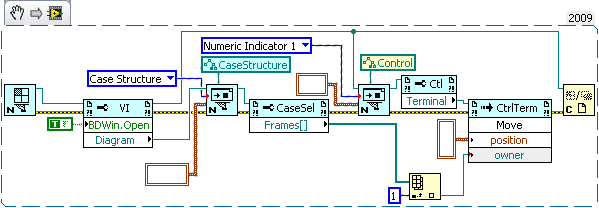
How can I put a digital indicator in a box structure using VI scripts
I am using VI scripts and I try to add a digital indicator within a box structure. I'm able to add the structure of the case and the digital display fine, but as soon as I determine the structure of the case as the 'owner' of the digital (rather than the pattern-block being owner) I get error 1060. Is there a way to get around this?
Note: I am doing this is because this particular (indicator in a case structure) provision will prevent a VI to be inline when it is built. This model will provide no functionality itself, it prevents only inlining. It is added to a larger VI which is used to initialize objects in a simulation, and there are many of them in the total simulation. If they are inlined, it takes a long time to generate the C code and a performance on this VI is not a problem because it is run only once at the beginning of the simulation. The rest of the screw must be inline for performance reasons. Therefore, I am open to other options to avoid a screw of Inline if 'the indicator in a structure of the case' can be done via the script.
If this is not clear, please let me know and I can clarify. Thank you.
Sorry for the mess, it works for me.
Don't mind the empty cluster constants.
-
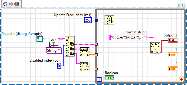
When the value to display in the time format double digital indicator... Changes in value.
Hi all
I can't display the values that I want. I have a value double say 320 sent to a digital indicator where I edited the properties of it to display in a time format that contains only minutes and seconds as Yes, 3:20 '. Unfortunately, it takes the value and change it to another value and display that. I don't know what is the issue. If anyone knows the solution... Please post!

There is an image attatched!
Thank you.
I believe only then due to the fact that when I convert a timestamp value to double as 03:20, he gave me 320. So I thought that the reverse can be trying. Should I just enter the total amount of seconds and that will show the Minutes
 econds I want?
Thanks for the quick response.
-
Size of analog input to see the digital indicator cover
I read a channel of analog input with several samples, and I want the magnitude of which is playing to display on a digital indicator which is on my front. I know that it is not possible to wire just the data directly to a digital display of the signal due to the difference in the data type. Does anyone have an ideal on how I can get around that?
Dear Thuillot
You can use 'Extract only your Information' function found in the range of signal processing.
You can find more information on this feature here
Kind regards.
-
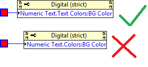
Solid color BG for digital indicator
I'm trying to programmatically set the BG color for a digital indicator providing a color constant to the relevant property in the attachment node.
However, I get only a stroke instead of the solid color background color. Cannot get on this issue.
You must use digital color Color.BG of Text.Text instead of digital color of Text.Color.BG.
-
I use the digital indicator for my Countdown to 0 (zero). The thing is I don't like when the number of numbers to 0, and then view - 0. Someone knows how to set the display to 0 instead of - 0.
Thank you
The only reason is could may show zero is if it's displaying a negative number slightly less than zero and is getting round. What is the representation of your screen? Is this double or is it all over? Maybe if you have validated your VI, we see what is happening and provide better suggestions.
-
input string to digital indicator
I get read values string in the following format
\s\s\s\s\s\s\s\s\s0
\s\s\s\s\s\s1000
\s\s\s\s\s75000
-\s\s\s\s\s1000
How can I format for digital and show them in digital indicator (I32) like
0
1000
75000
-1000
etc.
Read the characters are always 10 in number and I want that they to display the digital signature
Thanks and greetings
Hi rajxabc
Please check if this meets your requirement.
Maybe you are looking for
-
How to change the color of the background behind the characters in Pages
How do you change the color of the 'paper' where the characters are in Pages? I tried all kinds of things and I'm sure, one time explained, will be simple. But I don't know how to make the black characters and white background. It was simple in Wo
-
Can someone tell me how to combine many files into one big file? I know how to take individual files and put them into folders, but how do I combine multiple files into one big file? Any help would be greatly appreciated.
-
Battery handling with the HP HDX16t Premium Series notebook PC
Hi guys, I was just wondering how this PC manages the charging of the battery. As in, it completely cut off the power supply to the battery when it is fully charged, as if the battery was not yet in the laptop or would he keep it loads whenever he g
-
Error 2732 Directory Manager not no reprogramming
has received an error message "error 2732 Directory Manager not no initialization" which attempted to install a speedlink driver package meant for 64-bit operating system. Any solution please
-
Cannot install Microsoft Security Essentials. Continue to settle failed. error code: 0x8004FF49
Cannot install Microsoft Security Essentials on a PC. error code: 0x8004FF49