Table of waveform
I put the x axis to display the current time, but he does not correctly the value of y. If I start at 00:00 table then I would like the departure of the x-axis to read 00:00 and the next value on the x axis to be 01:00, but this does not happen. The first value on the x-axis change every hour. See the attatchemnts for more details.
No, the cleaning tool is to make your code readable.
If you call this case statement several times, which would explain your problem. The offset, in your case, would be to the start time. This should be called once - at the beginning at the start of your program. The multiplier is the time between samples. This would normally written only one assuming that you have a constant sampling rate. If your sampling rate is not constant, then you should probably use the XY graph where you write a time stamp for each new sample.
Tags: NI Software
Similar Questions
-
Table of waveform in time real Multi ground
Hello
I've attached a picture showing part of my code. What I'm trying to do is to create the exact waveform as "Cell pressure (kPa)", but in the x-axis in real-time. I created the "wave form" and that it does not work enough. This table will 'Y' to 'build the waveform"will contain 8 items and when I run the program,"Waveform"shows all the elements in a plot rather than in 8 different locations in a single diagram.
Can someone choose where I am doing wrong?
Thank you
Hoda
Hoda wrote:
Table of waveform isn't the time component. I need to show all plots on a graph and real-time
As you convert scalar data to a cluster to the chart, he has no information indicating the time. Missing time initial T0 and the dT for the time interval.
Outside your wire loop right now for the Xscale.Offset property for the graph node. Because your loop time is 1 second, you must set the DT. But if it was something else, you must set the XScale.Multiplier property as well.

-
Table of waveform LabVIEW 2009
I have a problem with the table of waveform in LabVIEW 2009, the chart will not poster on the table after a few iterations. This is a bug that appeared in LabVIEW 2009. The same program worked well with LV 8.6. Does anyone know a work around for this problem? I am currently using Version 9.0f2
See the attached diagram
It's strange...
I checked that save this return to 8.6 does indeed.
If you replace the function Merge signals with a bundle of things function seem to work fine.
There is also something weird happens with the property node. If you start with a pnode for active track, then drag it down to add another element, then change this new element to draw colors, you get an error on the property node.
"Interesting."
Steve
-
How to change tables of waveforms?
Hi, I hope you can help with this.
I read 6 channels of analog data to a USB - 6008 1000 samples/second, 1000 sample blocks in a loop. The data come from DAQMX as an array of 6 waveforms.
I want to (y) scale all data such as 0, 1, 2 channels are divided by 3 (because electronics has an op-amp of gain of 3 x on channels) and channels 3, 4, 5 are divided by 15 (because electronics has a 3 x the gain and there is a resistance of 5 ohms and I'm trying to measure the current).
You might think it's ridiculously easy... but:
(1) to "scale and offset" labview vi only works on waveforms (no tables of waveforms)
(2) insert a node of matlab or matscript me does not work only the tables on waveforms,
(3) with the help of a simple 'divide' VI, it is impossible to define the denominator as just one number... "3" !any ideas? as usual, it is the kind of problem, people have to face all the time
Dave
Hi Dave,.
That's how I'd do it - use the table of values of divisor.
Hope this helps - example in lv 8.6.
Kind regards
-
How to trace datetime against temperature table of waveform
Hi guys,.
I try to draw data from my table and to draw a time value date on the x axis and the value of the temperature which resemble 32.5 c
on the y axis on a cat of waveform. I'm new to studio measure, anyone have an example on how to proceed?
I have a loop that loop and gets the data from each row (time and temperature) and I want to draw in each loop, I leave,
If the graph will be a building, and the user can see until I read all the records.
Hi lil_racoon,
Thank you for the additional information. After looking at what you're trying to do, I think that the enclosed code will achieve your goal. Try to adapt it to the work of your application.
Thank you
-
How to determine the strict reference to the table of waveform
Hello
I want to change the properties of a waveform by programming. I used to get all references maps of waveform a function of range in my script VI VI. Then I typecasted references to more specific class (strict-single track) after this trial I was able set properties such as data history. Everything works fine but if I add a graphic that is multiplot, that this approach does not work.
The problem is that in the table of references, there is reference to a graph in multiplot waveform, and this reference is not possible typcast to the more specific category (strict-single parcel).
My question is: how to determine if the reference in the table is matching the proper waveform (single or multiplot) charts.
In the VI attached is a code that demonstrates my problem.
Thanks a lot for the replies
Jan
Thank you for advice. VI point 2 from your answer, I created and it works. The solution is attached.
If I understand it correctly. I need to know the type of chart to come.
My first idea was to create a VI in Drop that initializes all the graphics of VI on chart type independently.
But this solution is fine because I will only use graphics-single plot and multiplot(two elements).
Thank you
Jan
-
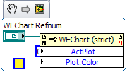
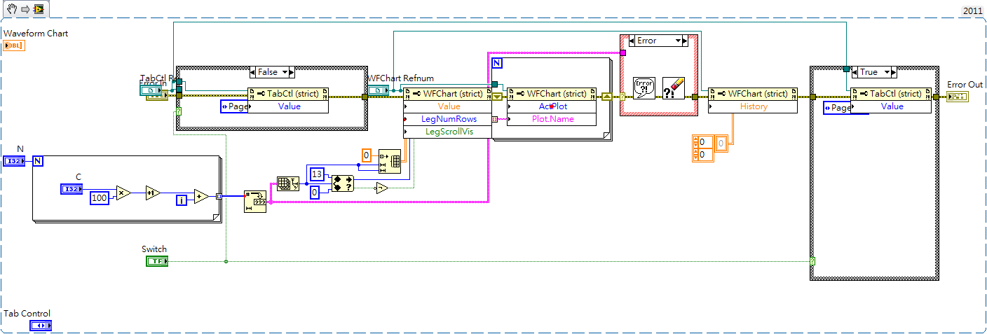
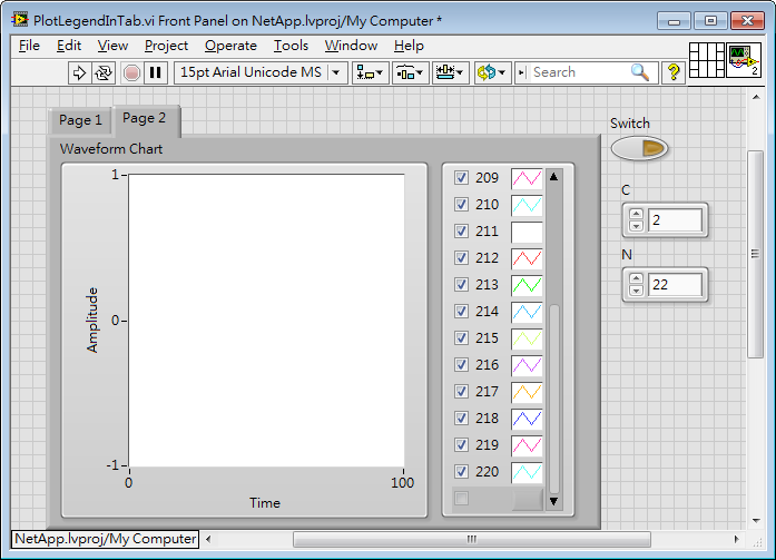
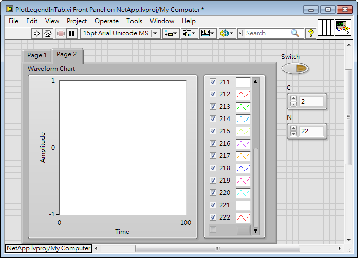
The table of waveform in the tab control
Hello
I would change the parcel number and the name of a waveform graph plotting in a tab control.
First of all, it works fine without a tab control, but I have several cards (such as temperature, pressure, tension...) while I put every chart in the pages of a tab control.
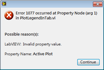
1077 error happened when I "add" the parcel number and change the name of the parcel.
Here is a sample I did to describe this problem.
Start, if the number is 20, there are 20 plots in this table on page 2.
t
Do not operate the switch, replace C 3, N-18 and run that and it can be seen that the tab control will pass to page 1.
Switch to page 2 and field names are updated, but left a relic.
Add N 22, replace C 2, and then run it again.
Error 1077 has arrived! Go to page 2 and the parcel number is always 20, and field names are updated at 20.
Run it again and it works fine!
It is very difficult for me.
If I spend first on page 2 and run the program, it works very well also.
(In other words, if the switch is active, then the program works very well.)
The version of LabVIEW mine is 2011.
I don't know I missed or misunderstanded something about this problem.
Is someone can give me any suggestions? Thank you very much

Step 1: Do not use tabs, use sub-panels. You can get the same user experience, but with a much simpler code.
Start here: http://www.notatamelion.com/2015/02/09/building-a-subpanel-based-user-interface/
Mike...
-
How convert the waveform on the table of waveform waving on waveform graph
Please answer now...
Your other post indicates it is a thesis, I consider homework. What did you do? What do you mean? What do you get a waveform graph? You have one, or the plots of 10? If you have a parcel, what you get as the data type for the data in the chart? If you have more than one conspiracy, what do you get? What is the data type that accepts a waveform graph? Have you looked to see how that is defined?
For example, let's say you have a parcel on your chart. When you get the data, you get... a table 1 d of values. It's kind of logic, right? Well, what is the type of waveform data? It consists of a starting point, time delta between points and an array of values. Hmmmm... So, what about using the wave function of build? Just a thought...
-
Insert in the table of waveform
This is a snippet of code that I use in a larger program, but the functionality remains the same. I read two waveforms of an oscilloscope and insert them in my DataSet happening in the world. For some reason, when I do the table insert, no data ever made in this table. What concept am I missing here and how can I remedy this?
Build table is the correct way about 99.9% of the time.
I don't think I've ever actually used insert into the table. It is intended for those situations where you want to Insert and in the middle of a table element, not when you want to build on the table at the beginning or at the end.
Your original mode has not worked because you wired the value of the N terminal in the insertion index in the table. This value is 3. If the next table in the loop is empty, then you cannot insert an element at index 3 because the rest of the table before does not exist.
-
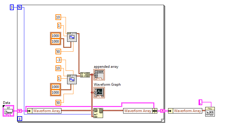
Limit the size of the table of waveform graph
I try to display two graphs to the user in the front panel. Data are data from continuous waveform with 5 channels at 10ksps. Chart 1 displays all of the data wiped out 1 on each slice of 50 samples and Figure 2 each sample but only for the last X seconds of data (adjustable seconds for the display of control).
This code works, but it lacks memory very quickly, because in Figure 2 all data is stored although only 10 seconds can be displayed. I have attached an image of a simplified version of the block diagram.
I tried wrong with Replace table subset and turn table 1, D but just may not be quite right. The timestamps are disabled, the timestamp is not incremenent, or the read buffer overflows DAQMX and it crashes. Does anyone have a suggestion on how to create an array of size ended up with something like a FIFO buffer so that will plot the graph 2 correctly? An example VI or the screenshot would be great.
Thank you.
The simple solution is to use the subset of waveform to get the data you want to display in the chart 2, then only write the chart instead of all the data.
As a comment, you may want to max/min decimate things data for chart 1 instead of simple decimation. It will give you a much more accurate chart.
The following message may be useful.
-
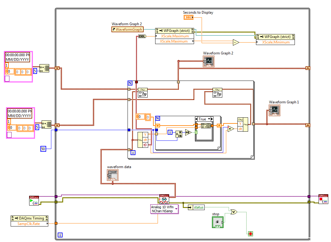
How to table of waveform of input 1 d in the lock with the amplifier
I have a LabView application that I have to change to include a lock in the amplifier. The application uses a capture card of data several times to capture a sample of 0.1 s of two signals (one signal, a single reference) in a laboratory test. Before the measure was made by the base RMS module to record the VRM in the signal, and the reference is ignored. However, the measures that I am now the scene run many s a lower and so I would use a simple RECS in the kit OR of.
I am happy (I think) with the configuration of GARLIC but I am struggling to understand the requirement of input data. It should be an array of 2D, with the identifited of reference signal. However, the output of the part of the utility that captures the waveform is a table 1 d of waveform. Could someone advise me on how to convert the table 1 d of waveform in a 2D table suitable for admission to the GARLIC?
As you may have guessed that I am a newbie to LabView, I try to modify an application designed and assembled by a former colleague, so I'd appreciate simple suggestions!
TIA.
You have separated for each signal waveform 1 d arrays, or do you have a 1-d single waveform chart where signals are separate items in the table? If this is the first, you should do something like the code below. If you have a single Bay, then the code would be similar - you could just use a table of unique Index function. You may or may not need to transpose the table 2D. I don't know what waits for the lock in Subvi - channel data by row or column.

-
Table of waveform and digital signal 2
Hello
I need to see 2 or more digital graphic USB6008 of waveform input signal, but each signal must be different offset, it is possible?
Just add a constant offset to the second signal between the Boolean value to (0,1) and the fiber node.
Lynn
-
Table of waveform does not change with time
Hi all
I have attached the VI I'm working. I haven't done any progress with VI after watching a few tutorials and read. I probed the entrance to the waveform graph, and it is simply not chaning over time (x-axis). What should I do? Data works very well.
Sorry end that. Here, it's in 2010
Dynamic data wires are blue SNO - they can take almost all data - (some of us older users despise them as much as express screws) hang a DDT directly by a waveform chart to your question the WC provided by default Datatype DDT. Conversion of the scalar measure express vi everyone downstream forced to accept that the data was just a simple DBL.
-
Incorrect data that appear on the table of waveform
I have two cards of waveforms in my vi, two current plot or tension. After that I created an array of data points, I send them to the waveform diagrams. The datapoints are completely incorrect when tracing (scale, no points, no autoscaling) Although, when I export my data to excel, it is perfect. All possible solutions on how to fix this? I have attached my vi for reference (sorry if this is a bit messy). I use the tab control and my problem is statement of the case "Ids vs Vgs.
You can cheat and use the graph XY Express or use a couple of dice shift registers of Y and build separate X. There is also the example of the graphic called expedition XY.
-
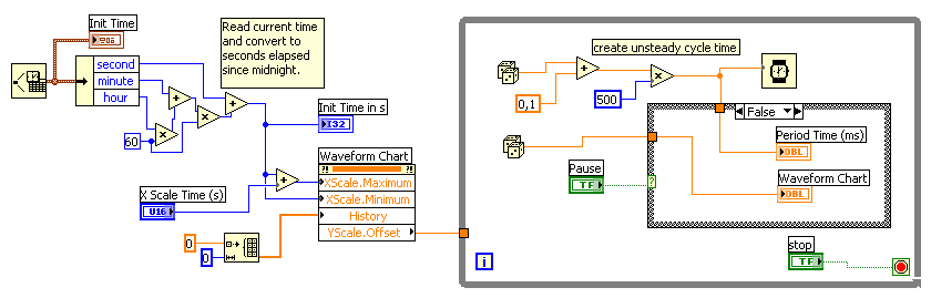
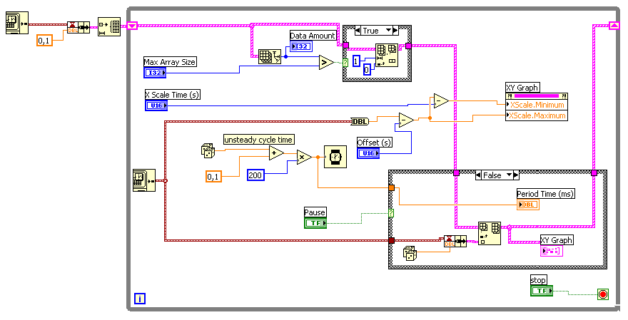
Problem with table of waveform: time scale do not see the time correctly
Hello
I have some problems with a graphic.
I want to display data, and the duration between two unique data can vary. It's something between 50ms and 500 ms.
The problems I have:
1. the time is not correctly displayed in the graph (allways 02:00:10 instead of the current time)
2. the data points in the table have a distance of 1 s (x-scale). This is not correct.I've tried several things, but I thinkt that I am on the wrong track.
Could you please help me?Johannes
LabVIEW 7.1 (!)
I'm sorry. The property on the left node was not necessary...

Maybe you are looking for
-
I use Safari "Version 9.0.2 (11601.3.9)" and everything was fine until about two days ago. For some reason, youtube seems to be not displayed properly (see the example image) Anywhooo... I use youtube a lot so it's causing a big problem for me. Anyon
-
Store data in a buffer of Labview
Hello I was wondering if labview allows you to store data in a sort of buffer or temporary memory to wait all the complete test and then export them to excel using the report generation tool? If possible, I would like to know how can I implement, bec
-
HP 21-2014: HP 21-2014 in a computer, Ram memory upgrade question
Hello, I have a HP 21 2014 all in one computer. He now has 4 GB Ram memory and an AMD processor. I was wondering how it would be possible to increase the Ram up to 8 GB. Is there a certain number of model or brand of Ram do I need to buy? I looked a
-
How can I add options for editing the menu in Microsoft Money 2004 drop-down?
On the tab edition shows cut, paste, copy. The Edit tab on Money 2004 helped me empty checks, remove any transactions, etc. What should I do to do to have these in the Edit drop-down? original title: do I have to do something for the software Money
-
Impossible to format my Sandisk Ultra Plus 16 GB MicroSD
Hi, I bought this product about an hour ago from Bestbuy. It was sealed in his case, there is no way, it was a homecoming. When I insert the SD card with the inside microSD adapter to my computer, it asks to format the drive. Then the Format Windows