This kills LabVIEW VI
When I run the attached VI (LV 8.6) it gives me the following message is displayed:
This message seems to be thrown when the program enters the loop For. I have re-written this from scratch twice now and the same error is thrown in the same place. I want to see if anyone can reproduce this on another computer and if so, if anyone has any ideas of how to fix this. I'm posting in 8.6 because it's the version that I am having trouble in. Any thoughts are welcome!
I can reproduce this too. There is definitely something wrong.
Possible workaround:
If you add real data to "array", so it is no longer empty, it does not crash.
If you do then the "table in" empty once again, it still works very well.
Go figure.
Tags: NI Software
Similar Questions
-
I use systec usbmodule1 to send and receive messages CAN one have tried this in labview?, if so can you send me the code
Thank you
Hey,.
All our drivers CAN have been written for CAN of National Instruments hardware (referenced here: http://digital.ni.com/public.nsf/allkb/E2C6ED025C798C5586256F4E00520448 ). So, you will need to manually, code all your communications unless Systec provides a LabVIEW driver. There could be several dll files Systec provides for communication, which you will be able to access through LabVIEW. Take a look at the node of library function call, which is in the range of functions under connectivity-> libraries & executables. Here, you can call a dll file, as well as the different functions in this dll.
I suggest posting your question either on the forum of LabVIEW, as mentioned previously, or on the forum CAN found here: http://forums.ni.com/ni/board?board.id=30
-
Installation of the USB-5680 kills Labview
Does anyone know why the software that comes with the USB-5680 power meter would cause Labview 8.2 no longer start successfully? I think that the error was: an unrecoverable internal error: lvint.cpp, line 1538.
Hello LabTech,
I don't know what is the cause of your problem, but you can try to replace the file ni568x.rc with the attached to this knowledge base article. I found a question where to replace this file corrected exactly the problem that you see. I would like to know if it works and if you have any additional questions.
-
How can I do this in labview: find the numbers of the overlap between bits
Dear
I have this problem it really so complex to solve for me
This isn't the House work its related to my academic research
I have two streams of bits, each of them with a length fixed k bits as follows:
x = 1, 1, 1, 1, 0, 0, 0, 0
y = 1, 1, 1, 0, 0, 0, 0, 0
I need to extract the following information
A1, the number of 1 overlapping: in this case is 3
A2, the number of 0 and 1 which overlap x of Y: in this case is 1A3, the number of 0 overlapping of X and 1 of Y: in this case is 0
A4, the number 0 that overlap on the two x, y: in this case is 4
I thank in advance
Best regards
Sorry, I was posting by phone earlier. Here's what you can do.

(If the berries are important, you must convert to I32 before summation)
-
How to convert this matlab labview code?
result = find (([(arrayofval > = minvalue); 0] & [0;)) (arrayofval< minvalue)])="">
([(arrayofval <= minvalue);="" 0]="" &="" [0;="" (arrayofval="">minvalue)]));
Thanks in advance.
-
Accelerometer: Can I do this with my labVIEW 8.2 Student Edition?
Dear anyone who reads this,
Sorry, but I'm still a beginner in this program. But I want to know if I can do this with labVIEW or not: I have an accelerometer sensor, attached to a flat surface. Of course there will be noise, but there will be times of impact forces that causes a significant acceleration to be detected by the accelerometer. I want to put a threshold to a certain extent so that only signals above specified scope will give data. Most of the time sounds will be below the threshold, but impact force will be causes acceleration to go above trigger level - by using a counter (to continually County time), I want to labVIEW to record and give wide/show time (which is recorded by the meter) at the moment the first data point is detected (which is the first data point magnitudes the trigger level).
Now, considering the impact creates soundwaves and they are very fast, as it takes a microsecond counter.
Is this possible?
A simple answer Yes or no would be greatly appreciated. Any additional comments are welcome.
Thank you
Hi Bangkok,
You will be certainly able to do this using LabVIEW, however, so far, the discussion has been clocked by the software approach. In LabVIEW, rather than use the mask and the limit test VI, I probably just use the base level trigger found VI here instead.

For best performance, you must perform this trigger at the hardware level. Any of our material of the M series low cost support material analog trigger. You will program these devices with our driver OR DAQmx. The installation of this driver includes many examples of LabVIEW which will help you in the right direction.
-
How to interface a simple way using LabVIEW 2009 simulink model and SIT?
Hello
I finally found a way to use a template simulink with LabVIEW and the Toolbox to SIT, but I'm not satisfied.
If you have any suggestions, the link of resource that I missed, please do not hesitate to answer
Note that I do not know much about simulink, so that is my question seems stupid, let me know what
Software configuration
OS: Windows (not an RT target)
LabVIEW 2009
SIT 2009
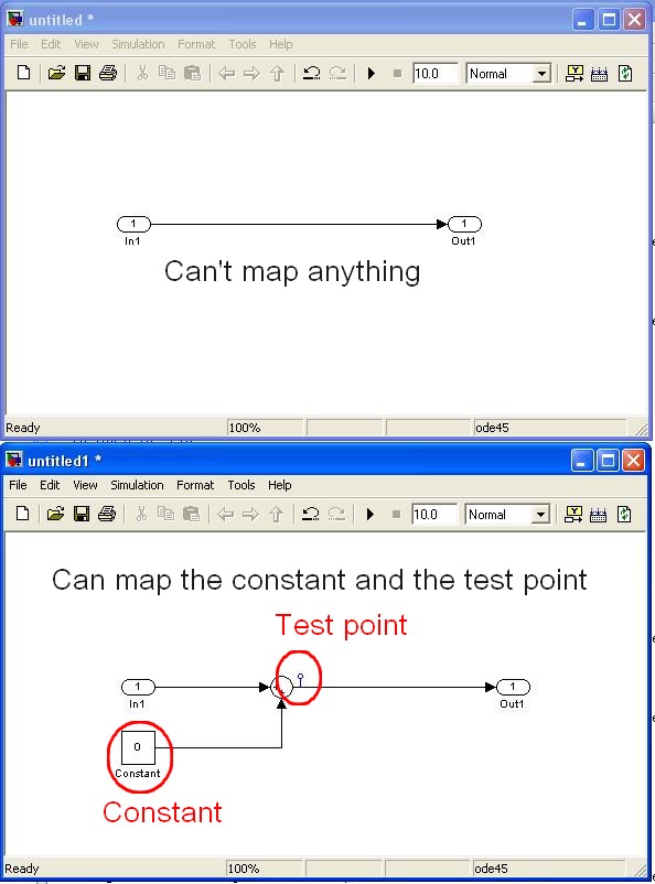
question 1: interfacing the model DLL (mapping considerations) with a driver VI
We have created a model of DLL by using the 'Workshop in real time' tab in simulink.
In LabVIEW, launch us the tool 'SIT connection manager' and try to use the DLL with a driver VI by mapping the e/s model for screw/lights orders.
The fact is that I fail to connect to my controls/indicators VI/o model because they do not appear in the mapping dialog box.
The simulink single objects that I managed to map are "constant" and "test points" while I need to edit the template simulink itself (example below)
Are in e/s model, not considered as part of the parameters of the model? (this could make sense because the mapping says in fact that it operates on "model parameters")
Is it possible to link the IO model VI commands/lights?
Note:
-the "configure HW i/o mapping" dialog box allows me to map model e/s with e/s HW...
-The examples also use these "constant" and "test points".
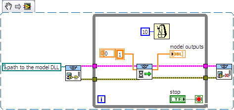
2nd question: use of direct screw SIT
I tried to use the DLL directly with the screws SIT (code example below)
This kind of code works well on another project (target of 8.0/RT LV) but not on the current project (LV 2009/Windows)
The second stage of the model never ends:
-0-index of the loop works as expected (model doing its job).
-index of the loop 1 starts normally, but execution is stuck in the 'SIT scheduler.vi.
Then I have no choice that to kill LabVIEW ("Reset screws" windows appear if I try to stop/close them).
Is there a reason that I do not see what explains this behavior?
Thanks for reading.
Any help appreciated.
Kind regards
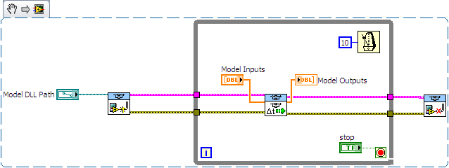
Hello
I spent some time analyzing the VI driver as you suggested.
Here are my findings.
Question 1: the SIT connection manager does not pass to the model SW controls/indicators. Only, it allows the user map HW AIs/AOs.
The only solution I found (to have a SW - for example a shared variable - object that is mapped to an input/output model) is to customize the VI driver that is scripted by the SIT Connection Manager ("_Base
rate Loop.vi" in the flat sequence structure named "read code") Question 2: after spending some time in the VI driver, it seems that the VI to call right is not 'SIT scheduler.vi' but 'If SIT take model no time' (which uses the other as a Subvi)
My conclusions are correct? If I use the API in the wrong way, please let me know.
Kind regards
-
After reading repeated advice to use a task killer, I finally decided to try it. After a week with disabled ATK, I must admit that it is true. My phone works more smooth and the battery lasts longer without the task killer. I was skeptical, since every time I killed tasks, the displayed memory free above ATK would rise and it was a good thing, right? Appearently not. It was finally explained to me that the processor gets run low power to keep these inactive processes just being run, but cycles up to full power to restart the services put to death. This is the info that made me try. But my performance of phones, it's what will make me keep this killer turned off task.
PS: I still use it occasionally to kill an individual application or two that I know is ill-conceived and won't close as it should be, but then I immediately kill the killer of the task itself.
You are absolutely right. My XT battery is very good without a killer get easily 30-40hrs with the right amount of usage. I'm still currently testing this belief with Taskiller I am also running, well Lite Panel System testing. Battery Manager that is filled with this camera is awesome. I've never used ATK. I perfer TaskillerPro.
-
Ethernet I / P Communication between Fanuc LR Mate 200iC and LabVIEW
How can I read the outputs and write entries of a device, Ethernet/IP, using the NI Ethernet/IP drivers?
I recently get the NI Ethernet/IP driver OR to communicate with a robot of 200iC Fanuc LR Mate using this communication protocol. In fact, I set up the robot as a parameter to map digital 1 to 64 and output digital from 1 to 64 and through the Ethernet/IP configuration.
What I do is for example, a specific moment in my logic to the status of an output of the Fanuc Robot to take measures, or give some input to the Fanuc Robot so do some operations. Now, as I noted above, I get this drivers recently and apparently they are new or regular technical support do not support for this product. Basically there is no apartment of the LabVIEW help on this driver documentation, and this help doesn't help too much.
So, if someone can help me to make this work I really appreciate it a lot. I'm in the middle of a project we showld integrate via Ethernet/IP. Here is a screenshot of the the inputs and outputs in the configuration of Fanuc Robot are on Slot 1. Attached is a table with a summary of the Fanuc Robot of the configuration settings that should be used to set up the scanner (in this case, LabVIEW):
I'm using LabVIEW 2011 with Ethernet/IP v1.2 drivers on a Windows 7 Professional
Once again, any help on this will be really appreciated. Thank you.
Hi Ferdinand,.
Please refer to the help as documentation below:
1. open LabVIEW, go to the Help Menu-> NOR-Industrial Communications for Ethernet/IP. This is documentation of EIP support for all applications.
2. in him getting started window of LabVIEW, please go to find examples. And check the directory:
Input and output hardware-> NOR-Industrial Communications-> EtherNet/IP
In this directory, there are several examples of use of the PPC.
And for your case, read the example in ".vi AccessAssablyInstanceData (Explicit)", which should be very similar.
For any question below, please do not hesitate to contact me.
Thank you.
Chris
-
PCI-4351 and what version of labview?
I have a Board of 24-bit AI NI PCI 4351 that I am tring to use with Labview 2009 on Win XP with 7.44 DAQ. Whenever I have a vl of the 4351 on the block diagram, I get an error message indicating that this vi is old to be converted to this version of Labview.
So I guess my question is, "what is the latest version of Labview to be compatible with the PCI4351 on Win XP and 7.44 DAQ card?"
It is clear that these VI have been created in LabVIEW 5. In order to open this VI LabVIEW 2009 you will need to register in an intermediate version of LabVIEW (LabVIEW 6 or higher). You can check it out on the table in the link below.
How to change to different version of LabVIEW VI: http://www.ni.com/tutorial/8387/en/
There is a forum of OR which allows display of VI and other users to convert for you, see the link below.
Conversion of the VI Version: http://forums.ni.com/t5/Version-Conversion/bd-p/VersionConversion
-Will.i.am10
-
A non programmable power supply with LabVIEW + additional programming hardware
My company is interested in the use of LabVIEW to automate a non programmable DC power supply. The instrument in question is the U8001A device, but the idea must be the same, regardless of the manufacturer (the instrument was purchased while I was hired, or I would have opted for one with SCPI commands if that's a thing for power supplies):
http://www.Tequipment.NET/AgilentU8001A.ASP?source=googleshopping&gclid=CMn-rPzAks0CFZM6gQodMu4McQ
We have two connectors that would be plugged into the power supply and in the 'brick' that holds some sample we want to warm up. This has worked well for our initial target, but we are now interested in time these events alongside 1-2 other instruments that we are exploited (for example a-ohmmeter for quality control), where we can control all this through LabVIEW. Say, only allowing the power reaching the sample at intervals of 5 seconds, with widths of 1-2 seconds impulse.
I'm sure I'll need a multifunction data acquisition device, and I already have my eyes fixed on the purchase of the NI USB-6501 (link below). My main question is about any additional material which is necesasry, if only a debate of ideas cenceptual on what I'm trying to accomplish. I can do everything I plan only through the acquisition of data, or are there other necessary materials, such as doors? What type of material is suitable for it? I apologize if this is the wrong sub-forum for this topic, as seems to be the subforum of material more appropriate upon publication. Thanks for your time!
http://sine.NI.com/NIPs/CDs/view/p/lang/en/NID/201630
Not even an analog command on this power supply... Range of tension and how much power do you need? You may be able to make an operational amplifier circuit, but find out who can handle that many likely power won't be easy.
Honestly, I say just to bite the bullet and get a programmable power supply. It will be cheaper as you try to make a personalized tour to adapt to a peg in a hole square circle.
-
Failed to retrieve the DIAdem DataFinder research data, using data-finder toolkit LabVIEW 2009
I am facing problem to retrieve the DIAdem Datafinder data.
At first, I developed this project in LabVIEW 2010. But because of a problem that I met in LabVIEW 2010, I thougth to work on the project in LabVIEW 2009.
Then, I reused the project that I created using LV 2010 using option economy for the previous version.
When I tried to retrieve the data from the tiara using data finder toolkit. I got a 305505 warning. Please see the attached message of Warninig.
But I have not seen this warning while I was working in LabVIEW 2010 and also, I was able to get the data from the tiara.
Please suggest me a way to solve this problem.
Hi Nanda,
There is a bug when using the SDK use in combination with DataFinder Toolkit 2009.
This bug is already fixed in LabVIEW 2010 and use SDK 2010. But as you said there is another question in LabVIEW 2010, forcing you to LV 2009.
I suggest you use LabVIEW 2009 with use SDK 2009 and DataFinder Toolkit 2009 and instead to use the "Waveform.vi results" to read the search results, I would recommend to use the screw storage. I spread your example VI and it attached to this message. You will still see the dialog box to search for "lvStorage.dll" but it will automatically disappear and the VI works anyway because in this case LabVIEW will find the dll itself.
My extended VI uses the '_openWithRoot.vi' to open a file with a different use than CT or PDM. This VI is also described in the following knowledge base article: http://zone.ni.com/devzone/cda/epd/p/id/4181
With LabVIEW 2010 use support has been enhanced and fully integrated in the standard palette of storage screws. So in LabVIEW 2010, you can replace the "_openWithRoot.vi" with the 'Open Data Storage.vi' standard but with LabVIEW 2010, you can also use "Waveforms.vi results" to read the search results.I hope this helps.
Kind regards
Eva -
Where can I find the Helper of Plot Bar 3D LabVIEW in 2014?
Hi all!
Sorry if this question is trivial. I know this is supposed to be pretty simple. However I fail to solve the problem.
I need to generate a 3D bar plot. For this, I found the attached example VI: 3D bar with custom labels chart 2013.vi. I tested this 2013 LabVIEW VI and worked perfectly. However, I have to work with LabVIEW 2014 (German edition, SP1, f3). When I opened this VI with the 2014 version, I get a broken VI.
I realize I don't think 3D Helper.vi of Plot Bar where I used to find it in the version of 2013 in my 2014 LabVIEW (see image of attachen). In addition the broken VI seems not to recognize the custom 3-d bar graph indicator.
I appreciate any help you can provide to me!
Sincerely,
Diego
Hello everyone!
I just found the cause of this behavior. The Helper of Plot 3D Bar is not available in the basic development system. It was possible to see in the 2013, because it was a trial version where the VI is available!
Thanks anyway!
Diego
-
Hello
I program of the United Nations (BAT - emc, a field generation software), which is supposed to call a labview llb and let him start the vi It contains.
On a computer, the operation proceeds as planned, but on another computer (that I must now USE), it does not work.
I tried to visualize what is happening with "Process Monitor", but I admit not knowing how to interpret all this. LabVIEW seems well try open the llb but don't about it apparently not...
I said that I have the demo of labview on both pc pour l'instant. I also put in the capture process by taking monitor PJ (it's not very readable in .csv so if someone a process monitor tell me, I'll send it en pml)
A big thank you to those who can help me...
I solved my problem: had to add "*" to export in the list vi, in order to allow the export of all the vi.
Thanks anyway.
-
Cloning a hard drive using LabVIEW
I'm trying to clone my laptop 476 GB HDD for a 450 GB SSD. The data on the laptop HARD drive are about 350 GB total, so there should be. Each commercial application, I've tried has failed to be cloned for one reason or another.
So I thought, ' Hey, I have a development environment, I'll do my own cloning software in LabVIEW! I understand that sector-by-sector copy of data is extremely low, but is it possible to do this in LabVIEW? My research drew a blank.
Thank you
Malcolm
Yes, unfortunately you have almost 0 chance to be able to do it using LabVIEW (except trying to hang in an application that does) as LabVIEW is a high too high level language - all file system operations pass by and get handled by the operating system.
As others have said, you should reduce the partition first, before you can move the disk - many tools better cloning can do for you. Unfortunately, I don't remember the name of the tool, I used to do it on my laptop but I certainly heard of the Acronis software before. Make a copy of the file in the operating system will not work because it won't copy things like the boot sector information.
There are also a few layouts guard/traps around moving a HDD to SSD (for most around things like sector sizes) - it is useful to have a read around this before you start.
Maybe you are looking for
-
My Favorites be saved if I off my computer and reinstall everythingback?
I have to reinstall windows on my computer, but I hope that I do not lose my favorites in Firefox, once I got everything reinstall. I hope that Firefox can record these for me once everything is done in a few hours.
-
HP ProBook s 4530: hard reset and factory reset the same thing?
Hello I wanted to know if the hard reset and factory reset are the same things? my laptop does not light and I discovered that I can reset hard, but I don't want any of my data on HDD to erase. is this possible? (I stop before so there is no data on
-
My FireFox bookmarks disappeared, there is nothing in the backup file, by chance, I found FireFox Bookmarks in the trash. How to make?
-
just turned on laptop and speakers don't work even tried to update this thing idt have no ideas?
I tried to download IDT and looked like it had not worked when I check and play sound the bar up and down as if something is playing but nothing doesn't come out. I even tried helmet still nothing. Any ideas? Thank you
-
I live in Wellington, NZ and am eager to try the XPS 13 Ultrabook before you consider buying. Anyone able to help?