Time triggered by daqmx measurement
Hey
I try to get a measure of the time triggered by a contribution by a NI USB-6009. The installation is a diode and a light sensitivity device. These must then switch between them a few times and I want to store the time every time they meet. Because I'm pretty new to labview I don't know how to solve this problem, so I hope someone can help  .
.
Best regards, Jesper
Hi Jepser.
I presume the USB-6009 case is the measure of the unit of light sensitivity. Is the signal of the digital camera? What is the calendar requriments for your application?
There is a generation to check on USB-6009 and that you can use for edge counting applications. By counting the edges and store the timestamp for each edge in Labview you can then calculate the time between edges.
Please let me know if it works for you.
Thank you!
Tags: NI Software
Similar Questions
-
Triggering and simultaneous measures
Hello world
I wrote a Vi to acquire data simultaneously from 7 devices. I use cDAQ9178 with NI9203. The vi will acquire current values 4 to 20mA. Could you please check the attached file and let me know if I need to improve.
I have a question and I would be grateful if someone can help me to answer.
1. how to open the binary file for writing to the file measured by EXCEL?
2 is it better to use write on the worksheet for data recording, if yes how to include the time column?
3. I will use external trigger via the port of PIF0 signal, is it OK to do with dag support? I have not yet tried, but it seems simple?
4. Finally, I have another vi for the valve which should be triggered with vi as, is their anyway to do it? I was thinking of the authors of the notification, but I don't know how to use
 ?
?Sorry to ask too I really urgently need all this. I should finish my Tuesday data acquisition system

Best regards
In your example above, you have the Setup to write it into a file measure so it renames an existing file. This replaces the file at each iteration. You must change this to add to the file. It's in the "If this file exists' section of the configuration dialog box.
-
Input analog frequency on DAQmx measurement
I have an analog impulse (amplitude varies) connected to my USB-6212 DAQmx device. I am looking for a way to measure the frequency of the signal. So far, I have found no method DAQmx supported to achieve this. I'm coding in LabVIEW and the only way I found to do this is by writing my own code for the analysis of signals amplitudes to determine the level of half-max to find fronts and edges in order to count the pulses to calculate the frequency. Someone please tell me there is a better way. I need help on this one guys.
With an analog capture, you can try the function extract your unique information on the Signal Processing > range of measures of waveform. There are also Express your measures VI.
-
In the control loop time interval and simultaneous measurement
Hello world
I just started to learn labview so please do not judge my messy programming

I want to constantly measure certain values (humidity, temperature, etc.) and once a certain threshold is crossed, I want to activate a device. Measure and activating things works perfectly if used separately. If I combine it and measure for awhile (10 samples at 100 Hz continuous playback mode) I get the error 200279 "attempted to read samples that are no longer available.
If I use (100 samples to read 100 Hz n samples) it measures for some time (interrupted manually after 4 hours), but I recognized that there was a gap of time of half an hour between the timem system and the 'real' time shown in the table.
Oh, and this isn't really critical time. It is enough if it measures one sample per 5 seconds or more.
Is there a quick fix and dirty for this?
Thank you for your very long in advance.
Hendrik
-
Loop root, time travel and DAQmx Watchdog
I just ran into the issue where time travel calendar control blocks the execution of my system. See here to discuss this problem.
I have a data acquisition loop race which uses the DAQmx watchdog and open this browser window is causing my dog die of hunger, which causes the stop of my application. Curiously, when I opened the drop-down menus, as shown in the above thread Jack, I don't see the same behavior. It is not really clear to me what the original block, but do not have drop-down menus.
I wonder if anyone has suggestions for workarounds in addition or explanations.
One solution, I did it in the past to solve this problem was to create my own dialog box Date/Time in LabVIEW and hide the native button and add a normal button to the face before that this dialog box was invoked. Given that this makes the dialog a normal VI the problem of root loop is not present with it. There is a VI in resource/dialog/picktime.vi that looks like the dialog box used in the date/time picker, but it isn't since changes to the present VI appear not in the native dialog box. LabVIEW seems to use an internal C implementation of dialogue which is the root cause of the loop of the root being blocked since the message of dialogue Manager is running in the same thread as the loop of the root.
Create a copy of this VI into your own project and adding it through your own browse custom time should solve the problem.
-
USB-6225 DAQmx measurement problems when using a voltagesplitter
Hi guys
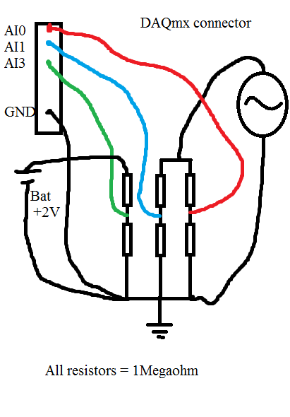
I had a serious problem regarding the use of DAQmx USB-6225. Please look at my diagram below:
When I measure the waveform sine on AI0, everything is OK. Even with a very sampling rate high as 80kS.
When I measure the waveform sine on AI1, everything is OK. Even with a very sampling rate high as 80kS.
When I measure the battery voltage on AI2 CC, everything is OK. Even with a very sampling rate high as 80kS.
Now comes the problem:
If I measure all three analog inputs or the two and two together, I get a very different result when I measured one and a single channel. If I add more channels (i.e AI3 and AI4) on my USB-6225 DAQmx, without connect anything to them, I can see the sinuses even as I do with AI0 AI1, but with less amplitude.
When I measure the voltage as well as AI0 and/or AI1, the domain controller becomes sinus armor as well. If I connect the + 2 V DC directly to data acquisition without resistance, I see a line perfectly DC on my chart, but with the sinus AI3 and AI4 top.
If I use an oscilloscope and measured directly on the same wire that goes to my data acquisition and the resistorcoupling, I can see small pulses of the samplingfrequency and the signal seems quite noisy.
That's my big problem:
Everything works perfectly if I use R<100Kohm. any="" value="" below="" 100k="" is="" ok.="" this="" coupling="" on="" the="" schematic="" is="" just="" a="" test.="" the="" trouble="" comes="" when="" i="" need="" to="" measure="" a="" circuitboard="" that="" draws="" energy="" from="" a="" capacitors="" in="" the="" circuit.="" if="" i="" use="" any="" resistors="" below="" 1megaohm,="" it="" draws="" energy="" from="" the="" circuitboard="" and="" the="" test="" is="" not="">
Anyone with some experience around this problem? The impedance of the analog input on my USB-6225 DAQmx is 10Gigaohm so it should not really been an issue.
Here is what I tried:
With the help of a D - sub cable with shield. I tried to use with no shield shield closed, I have both ends and closed, the shield only on my DAQ.
I checked my code and also just used the DAQ assistant.
I checked all parts off my setup for groundcircuits and I twisted each cable from any power supply, the signalgenerators, the DAQ cables.
I have connected my DAQ to mainsground (in the wallcontact 230V and Yes, we use 230V in Norway). Also any other equipment.
I connected without mainsground. Also any other equipment.
I tried cables as short as possible.
I tried to use the differential, CSR (Respect to GND), NRSE (Respect to the sense of IT). Nothing has worked.
I tried to use as sample rate and samples possible. (It helped a little when the DC measurement and AN analog input. If I tried all three, he has yet again).
All this comes to mind that the USB-6225 DAQmx cannot manage measuring more than resistors with values around 1Megaohm and above.
The answers will be rewarded with congratulations and a sincierly 'Thank You '.
Hi guys again!
Bother replying this thread

I'm a guy. I don't read manuals! But now that I did... And. There are 4 pages describing my problem and what to do about it. So problem solved
I have experience ghostvoltage of the other channels due to the high - impedance of the source. I created a follower of tension with an op-amp and the problem disappeared! Thank you ni.com/info/f/. Do you have answers for everthing is there to inquire. Except why I ran out of beer. mmm beer!
-
Is it time stamp with daqmx read
Hi all
Simple question. I have currently not creating a task or starting a task, I simply create a channel and reading that chanel.
It is... Why I don't get a timestamp when you do and do I create a task to get one of this?
There is a timestamp when you use the DAQ Assistant or when you choose to return a data type of waveform with DAQmx Read.
You can't do a reading without a blemish. You don't have to create the task in MAX, however.
-
How to choose destinations for counter/timer signals in NOR-DAQmx?
In the document M Series DAQ
M series user manual
622 x, NI 625 x and the materials NOR x 628
M series user manual
July 2008
371022K - 01appears on page 7-30:
Counter/Timer default pinout
By default, NEITHER-DAQmx routes counters/timers and outputs inputs to the PFI pin, shown in table 7-4.
Table 7-4. 68 peripheral pins by default Counter/Timer pines NOR-DAQmx
Counters/timers fail-safety connector 0 PIN (name)
0 2 CTR (PFI 12)You can use these default settings or select other sources and destinations for the
counters/timers of NOR-DAQmx signals. Refer to the connection counter signals
in the NOR-DAQmx help or the help of LabVIEW in version 8.0 or later for
more information on how to connect your signals for common counter
measures and generations.I couldn't find any hint to the appropriate command of DAQmx in the "NOR-DAQmx C reference Help" to select other destinations for counter/timer signals in NOR-DAQmx.
Please can you tell me the DAQmx command right? Thank you very much.
I use the NI USB-6259 M material Series DAQ, BNC end unit.datafriend,
If I remember correctly, you can "free" the output terminal of default counter by calling DAQmxSetCOPulseTerm and passing an empty string in the 'data '.
Hope that helps,
Dan
Edit: You can also set this to any other valid terminal (IE... "Dev1/PFI0") and to send the output to.
-
Neither daq 6009 - delay in time between the measures
Hi all
My first post
I have a small question about the acquisition of data with the NOR-DAQ 6009, where I try to get one or more number of samples per minute. Let's say I want to wait for some time before taking a measurement. I don't know how to do this. I tried to figure it out by myself, but because I am completely new to LabView and I come from the OR-6009, I was wondering if someone can help me here.If this is useful, I enclose the .vi.
Please let me know if you need more info.
Thanks in advance.
You would get the timestamp before the average like I said or just call to get Date/time according to the seconds. Example below. You can recreate a waveform data type or do whatever you want with the timestamp and the average.

-
measurement time and openness 4132
Hello
I use a 4132 SMU with a switch 2531 to measure different resistance in an electric circuit. I use a brief biphasic pulse of 50ms ~ to measure resistance. My problem is the measurement time if long - it seems that the minimum pulse width I can do is a 30ms pulse in a polarity and a pulse ~ 40ms in the other polarity. I disabled 'way' that knocked 20ms on each phase, but I am still left with a ~ 70-80ms measure, but I wish it were half that, if possible. The only other way I can see to minimize the measurement time is at the bottom of the window opening, but any if I increase or decrease the time of opening, the measure takes about 10 x longer if the opening is none other than 1 PLC.
Attached is the Subvi I use to measure the unique resistance value. Note that first I close the relay to solve part of the circuit and then configure the SMU and then get several measures, one for V (+) and one for the (-) V. This measure will be repeated 15 times in quick, although succession with different closed relay, which means that the SMU gets reconfigured/initialized 15 times with the same parameters, so maybe that's my problem. I have not ventured into the handshake, but I would like to know if there is anything else I can do since the handshaking deal would take a lot of programming. In any case, when I run the VI several times, there are only 8 ms between biphasic pulses, so the reconfiguration may not take THAT long.
I posted a jpg file of the time trace of the impulse it generates (10,000 samples per second). Note that the first phase of the pulse is a different length of time that the second phase: there is nothing in the program that would cause - it would be more logical if the first phase was more time on behalf of increasing the time for the configuration of the SMU. So I have sort of a bunch of problems here: 1) cannot reduce opening time 2) want to avoid a handshake VI if it means hours and hours of programming, 3) uneven pulses. I hope someone can point me in the right direction!
Thank you very much
GimNPC
gimNPC,
As mentioned earlier, you should not call Reset every time at the end of the method. Instead, set the output to 0 c. Moreover, all the attributes that are not changed will not need to be reconfigured, which will speed up the loop a little (maximum, that I would expect several milliseconds).
When you call niDCPower Reset, the opening time is reconfigured. On the 4132, anytime, the opening time is reconfigured, must wait a minimum of time to allow a measure being erased. It is because of the behavior of one of the hardware components that we use. If you prevent the reconfiguration of your opening time during each run, your speed should be improved significantly.
Please let us know if these suggestions help, or if you have any other questions.
Thank you
Tobias Gordon
Software engineer
DC accuracy
National Instruments
-
Measure the time of the rising edges of a digital stream using a USB-6341
I have a DAQ USB-6341 map.
I use Measurement Studio (writing code in c#) on a Windows 7 computer.
I'm relatively new to the DAQ cards, programming, so I could ask something that is obvious (sorry if this is the case).
I went out a stream of digital pulses to an analog output channel. I wired this channel to one input of the meter channel. I am able to measure the number of edges upward to the inlet of the meter channel (since the digial flow is continuous, the number of rising edges increases with time).
I would like a time stamp of each rising transition and I like to keep these timestamps in a table without ever growing (or maybe bin these timestamps in a histogram).
Set up the meter channel to provide the timestamp data? (rather than just count)
Thank you for your help.
WRB,
The meter must be able to measure the relative time between the different edges of your signal. To do this, you will take care to set the meter to measure time. It will measure how long a full period of your signal takes. You can configure edge that you want to start with. You'll want to set up your timed 'implied' measure. This sets up the meter to automatically take action whenever a period is over. While it's not exactly a timestamp, you can find the distance between two edges by adding the time periods between the banks in question.
I see another technique that you can use. This would put the counter to edges of County one of the basics of time of your device (it has 100 KHz, 20 MHz and 100 MHz bases long). Then configure the task to use your signal as a sample (configuration to use rising edge) clock. Whenever the song occurs, you will get the number of ticks ticks selected timebase that took place at that time. One thing to note here, however, is that the counters are 32-bit wide, so your code will have to manage the overthrow of this charge if you are using a fast time and base running for long periods of time.
Hope that helps,
Dan
-
Is there a programmatic access to the Calibration Wizard of DAQmx channel in LabVIEW?
Hello
I'm making my own external calibration of my SMU-4300 OR against a HP 3458 A using an amplifier to the source of several different voltage for the 4300 points. I use the channel calibration Assistant in the DAQ Assistant to my virtual channel manually set and save each point. This utility works great for me because I don't want to accidentally erase the external calibration constants and adjustments are seamless later (without having to apply one of the constants of calibration every time I have a measurement, it has simply everything for me in the background). The only problem is that manually configure each condition to calibrate is extremely slow and tedious; I want to speed up the process by creating a VI that opens/closes relay and resolve tensions that I want to calibrate.
I was looking around the Calibration DAQmx palette, but I was unable to find a screw that had the same effect as the wizard of calibration channel without changing the external calibration constants. Anyone have any suggestions to achieve this? Worst: I'll create a linear scale and apply it to my channel, but I have to find a way to merge it with the already existing scale...
Thank you
Jack Grantham
Validation engineer
Texas Instruments
Hi Jack,
I recommend you to programmatically create a custom scale to correlate your reference known to your desired reading levels. You can then apply this custom scale for all the tasks you want to apply benchmarking. This knowledge base article explains how to create a custom programmatically through our API DAQmx scale:
http://digital.NI.com/public.nsf/allkb/F7DAE47B4408A86F8625765700767FCD
Who will work for you?
-
DAQmx: (almost) synchronous Continuous Acquisition / how to trigger Council transfer buffer?
Hi :-) :-) :-)
We have an NI USB 6289 acquisition card. I would like to continuously acquire an entry of 'almost' analog synchronously. How synchronous 'almost', I mean that when a Read DAQmx is executed (anytime), I would be able to recover all the data present on the PC AND buffer all data present on the stamp on the card at the time of the read command.
In order to test the behavior of the DAQmx Read, I used the following DAQmx vi (for a life-long real I would need a loop structure, but it's just a theoretical experiment):
DAQmx create task
DAQmx Create Channel (polymorphic instance HAVE voltage)
DAQmx Timing (instance polymorphic sample clock, Mode sample set on samples continues, the rate set at 1000)
DAQmx Start Trigger (polymorphic instance Start / None)
DAQmx beginning
Here the program waits n seconds (variable), then
DAQmx Read (instance polymorphic analog Wfm/1Chan N Samp, number of samples per channel-1).
Buffer FIFO of Council seems to be large 8192 samples.
If the time between the beginning of DAQmx and DAQmx Read is less than the approximately 8.2 seconds, DAQmx Read recover whatever it is, if it is more than 8.2 seconds, DAQmx Read retrieves 8192 samples. I expect this behavior: fills up the buffer Board it triggers the transfer of all data in the PC buffer and DAQmx Read reads the buffer of PC, it cannot recover data after the transfer has taken place.
What should I do in order to force the transfer of data from the buffer of (even if not full) Board to the PC at the time of the DAQmx Read buffer while the timing is in CONTINUOUS mode? I would like to be able to recover all the data from the buffer of PC and the Board of Directors in order to have all the most recent data and without having to put in place an acquisition of finite samples and a circular buffer of software.
I tried the DAQmx channel property node Analog Input/Properties Advanced options/General / Data transfer and data/memory transfer mechanism and set set of e/s, but it doesn't work or the DAQmx channel property node Analog Input/Properties Advanced options/General / Data Transfer and status of application for data/memory and set it to Onboard memory Custom threshold but I could not access the property of Custom threshold (this is not there!).
I'm sure there's an easy way to do this but I did not understand as yet...
Thank you!!! LucaQ
I am inclined to agree with Ravens Fan. However, assuming that you must use the USB DAQ for your application, a better way to implement your code would be as follows:
-
PXI-6230 and differential measures
Can you use the 6230 for closed measures the differential and unique at the same time? Only 2 measures for Diff and 10 for itself? What do I have to configure it somehow in MAX?
Thank you.
Of course, you can mix the types of channels, although the 6230 has only 4diff/8se and not the number you mention. You can do it in MAX or in your code. In MAX, just select the configuration of terminal for each channel. I know not what programming language used because you don't mention it, but if it is LabVIEW, you use just a function separate from DAQmx create channel for different channels and themselves. Don't forget to take into account that each diff channel requires two real physical channels. So, if you select ai0 for diff, which also uses ai4.
-
What is the unit of time by variable (dps.metered.dwelltime) messages to In - app?
And where is the documentation of Cloud Mobile Marketing? I'd love to see how all these key context are defined and what units / syntax, they expect.
The Analytics team:
Please see the Report Analytics for AEM Mobile Guide
Sent each time that a measured section is previewed above the pause time. The pause time is longer on shelves of phones and is reported in this event.
"The pause time triggers are 25 seconds for a Tablet and 15 seconds for a phone . " .. We will add this to the documentation.
Hope that helps.
Maybe you are looking for
-
Windows 10 for Officejet 4500 driver
Hello I've updated from windows 8.1 windows 10 and after my windows activation, even once, I did a clean install of my windows. After a successful installation and activation of windows, tried to install the printer driver using the driver windows 8.
-
How to get the display driver for hp250 g1 for windows7 32 bit
Hi, I bought a laptop HP 250 G1 & installed windows 7(32bit) but I'm not able to find the display for this driver. The i found on the site of hp drivers named AMD graphics high definition hd extracted al drivers driver in drive c, but there is no dis
-
When I right click on the desktop I no lnger didn't get the menu drop-down normal.
Y at - it a shortcut or another way to trigger this menu, or repair my right click?
-
My computer, I cannot access my account even though I have the password.
I have problems with my user account on my laptop Inspiron 1525 Windows Vista. Although I tried to type my password to access my account, it keeps giving me a message. The message reads: "the user profile Service service has no logon. User profile ca
-
HP Laserjet Pro print FAX error messages M127fw
My M127fw Pro Laserjet prints an error report anytime that the incoming telephone line becomes active. It's a line for FAX use only, and there is never intend to use this to talk. Given that any appeal could only be a robo call or a solicitation, a