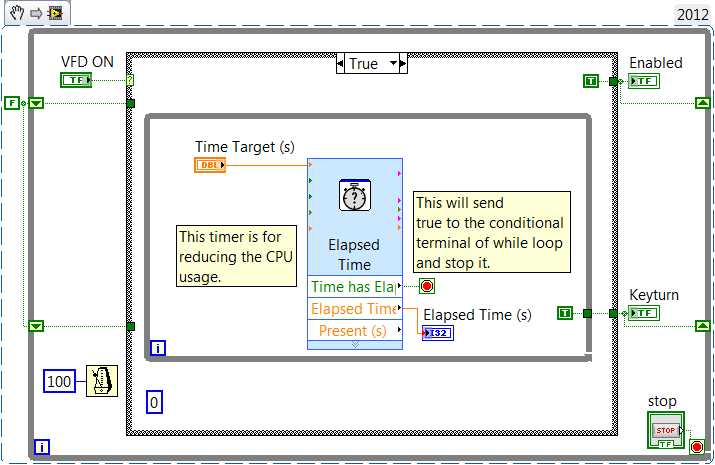
Timed Boolean switches with case structure
I'm trying to implement a control for a switch that, when enabled, a signal of 'essential' lights up for 2 seconds and then turns off, as soon as the essential signal sat for two seconds that the VI should send say that the switch is turned on. I can't get it work the way I want to. I think it might be a way to do it with a machine to States, but I don't know much about them.
Hello
I changed your Boolean lock so it will break again in the off position. This stops the VI into the case again and again until turns off. Then I added two registers to hold the values of the indicator to shift.
I guess that my bias is that you would like to continue to operate in the while loop, which goes back to the case of 'OFF '. If expand you this to a state machine, you might have several cases, shift registers would provide the 'flag' access status to other cases.
It is a single method, it fits your application. How would you install it in a larger design?
Copy the snippet on the desktop, drag on the VI.
Did you want the keyturn to turn on for two seconds and then have the activated LED light? If so, you have to move the location of the indicator in the target time while loop, this will in turn while the target time loop times two seconds.
Tags: NI Software
Similar Questions
-
Operating a SG200-08 switch with case removed.
I'll put a SG200-08 (8 port switch) within a 2U rack mount chassis.
To improve cooling I thought I'd take off the outer case.
Is there or are there problems with the help of the switch with the cover removed?
Thank you
Glen
Hi Glen, the first question would be, the warranty is voided and you are not entitled to any help. The second question is static electricity and environmental concerns. The third question would probably be your property insurance.
He is strongly against the recommendation to alter or change these units.
-Tom
Please mark replied messages useful -
Boolean switch until released by using a structure of the event
I use a Boolean control with mechanical action to activate the button, I want to return to the original state.
I use it in a structure of event defined to trigger a change in value. The action to push the button generates two events in the State on one and the other for when he returned to the stop State.
How can I control this to prevent a single event is triggered and the second event which is put on hold until is ignored, I want the button to return to the original state and not to execute the code twice.
Thank you
Jim
Right, I should have told latch. Do not forget to place the control button somewhere it will be read to reset the latch. It does not need to be connected to anything, just read. Sitting inside the case of the event is very good if you do not use anywhere elsewhere.
-
Control relay with Boolean switch using DAQ assistant 9481 - problems
Sorry for what may be a stupid question but I'm stuck in quicksand.
I use a relay module 9481 and have two external relays connected lines 0 and 1.
When I create a digital output 0 line by line, I can run the test inside the express and activate the relay and turn off without problem.
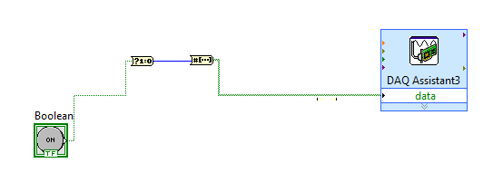
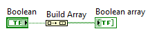
The generated block DAQ expressed expects a Boolean input of 1 d. (See attached photo).
I want to connect a Boolean switch relay line disk 0. You can connect live not because the switch is Boolean and the input is Boolean 1 d - I'm a conversation in the pict.
All plumbing lines display results, the relay never active.
Any bunch would be greatly appreciated! Thank you
Mr._Mechanical,
Welcome to the Forums of switch OR this forum is generally intended for products OR-SWITCH [such as the NI PXI-25xx & NI SCXI-11xx], I think I know the answer to your question.
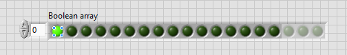
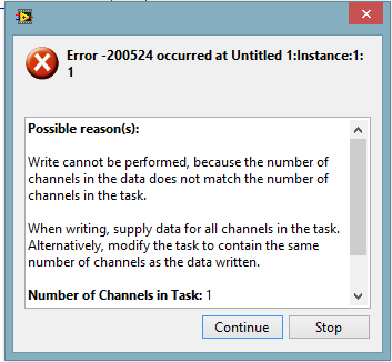
I think the reason why it's a failure is the conversion you make generates a table of 16 Boolean [as the 'boolean to (0,1)' function creates a data I16 type] with your data more false data points 15.
When you try to control the relay, he sees 16 datapoints are you Commander to a single port [channel] and so error out.
My suggestion would be to use normal DAQmx digital output screw [with, he set up as ' Digital > single channel > single sample > Boolean (1 line) "] rather than the DAQ assistant.
If you use the daq assistant, simply by using the function 'Building the table' will transform your simple Boolean data point in a Boolean array containing a single element.
While the DAQ assistant is very easy to use, I recommend that you use the DAQ assistant, because this reduces the features and increases the execution time.
-
Synchronize the case structure with enum update
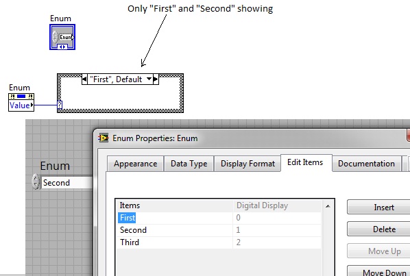
Hi, I created a control enum initially with the "First" and "Second" values. In the block diagram, I created a node of this enum control property and it is connected to a box structure. The structure of business allows me to manage the condition "First" or "Second" correctly.
I then modified the items in my enum so there is now a 'third party '. My problem is that structure business conditions still show as 'First' and 'second '; That is to say, I can't handle the "Third" condition My question is how to synchronize my case structure to show the updated enum values?
VI, attached, the sample created with LabVIEW 2009 version 9.0f3 (32-bit) running on Windows 7.
Thank you all for your help in advance.
Michael O'Shea
First tip: remove the value 'default' first case
If you have done your VI pauses when you change your enum, which is a good thing.
Now to synchronize, do a right-click on the border of the structure of the case and select 'add the case for all values', this is the option you are looking for.
Tone
-
Hello
I'm using LabVIEW 8.0 and I'm trying to create a subgroup of experts which shows the façade of a subvi according to the choice made by the user via the menu drop down Enum. I wired the Enum to a case structure and apply a coding identical to each structure of individual cases with the exception of course change the source of sub - vi. However, you receive an error "The VI isn't in a State compatible with this operation." I have managed to make a single sub - vi work within a subgroup of experts using a true/false case structure and the same exact coding. However, now that I use an Enum box connected to a structure of the case, I get this error. I enclose my diagram as well. Could someone help me as to where it is that I am wrong?
Thanks in advance!
If your VI runs already, when you try to run it? Which returns the error you get.
Check the State of VI before trying to run or make an error handling.
-
I have a business (with 10 cases) structure and I want 2 of them to be included in a loop.
Hi all
I'm new to this forum and I have a question.
I have a business (with 10 cases) structure and I want 2 of them to include in a loop.
How can it be done?Thank you.
mosheg.
Use own State Machine, where you can select the case according to your needs
-
Using switch and case with Radio buttons
Can I use the case switch with radio buttons?
What will be the parameter to determine the choice like xfa.event.newText is used for the drop-down list.
Aditya
Hi Aditya,
Select the exclusion group in the hierarchy (you have no script each option button) and select the click event. The switch statement would use the this.rawValue.
Hope that helps,
Niall
-
How to detect the correct sequence of Boolean switches pushed
Hello
My program is all what I want too. However, I need to have the Boolean switches (digital inputs when wired to the equipment) be detected in the right sequence. There are 16 switches on a Board of material. The test subject is displayed 3 colors before hand and the sequence of buttons to push when prompted on the screen with one of the colors, each color pertains to a specific sequence of 4 switches pushed on 16 as quickly as possible. The sequence of buttons remains always the same according to the three colors red, yellow, blue.
In the program, which is 99% working properly I tried to use a sequence of plate. It will give me a real if I hit the switches correctly - but will also give a real if I hit them back etc... I thought that a flat sequence is read from left to right?
Then I messed around by using a structured event - the array of switches, pushed index and compare it to a table of values control. I understand how it works, but the correct code is elusive.
I have attached a picture of program I did but it lacks the proper sequence. (Flat sequence)
I have included the code for the structured event that I messed with. Don't laugh - I was just making experiences - I've never used a structured sequence before configuration.
Hope someone can help me.
Ned
Hi Ned,.
Your producer-consumer model is actually very close to work. In the original version of screenshot, it seems you are trying to use the structure of sequence to capture the order, but in reality you will capture only the AND logical of all the 4 buttons with no information about the order in which they were pressed. The structure of sequence does not by itself is waiting for an event to happen inside the frame, it which means that all 4 frames read as fast as the processor moves to their reading - which will be very fast.
I've made a few changes to your VI and renamed him Rev 1. See if it makes a little more sense with the notes I made on the front panel. I also did a different version with a loop simple and some added functionality (-Ko), just in case Your ' e interested in another way to look at it.
Kurt
-
I have a simple application, where I use a pneumatic cylinder using the compressive force. The user enters a set-point of load in the front panel and my LabVIEW program reads the force coming from the load cell and adjusts the current in an electric regulator to control the load to the desired value.
I would like to have a Boolean simple of LED on the front panel to warn the user if the actual load is in about 2% of the set value that they entered. For example, if they have 100 N entry, I want the Boolean value of LED to be green when the load is in 98 N and 102N and red when it is not.
I thought that I would need a structure to deal with a numerical range to control the Boolean value. The problem is that the load set point will change based on user input, so the beach in the structure of the case will change. Is it possible to use the structure of the case where it can use the percentage of the target value of load as the limit for the beach? Or y at - it another way to code this feature?
Thank you
Russell
You can't do that with a case structure.
You want to look In Range and force.
-
Hi I am new in programming with LabVIEW and I try to create a program that allows to estimate gear changes based on how fast the vehicle of support falls. The speed is measured by an OBD device and the results are saved in a spreadsheet. I created a sample program that contains a loop that reads the table of speeds of line by line. I then created a case 2 structures for example 2 speed brackets each support represents a gear (3rd 35-54 km/h, 4th gear gears 55-79 km/h). My problem is I want to count how many times the speed changes of support from one to the other to symbolize a change of speed. Right now my program will count only the number of speeds within each support the entire speed range.
So in summary I need help, trying to create an effect of negative feedback while first gear which falls within a range of speed is counted as a speed change, but none afterwards speeds are counted until a new slice of speed came.
I attatched the logfile and VI of suggestions would be greatly appreciated!
Thank you
Michael
Hi Michael,
I made some changes to your code
1 replaced the 2 structures dealing with one, which displays the report.
With the help of numerical values (instead of Boolean values) as the case selector - you can use whole; I see in the file CSV that all your speeds are integers of anyway, but I added a bit of code that allows to convert an integer, rounded down. So where logic says 35-54kph inclusive, because whatever between 54 & 55 be have been rounded down, this will also take to speeds up to 54.999999 (etc.) if need be.
I then sent this 'current gear' variable to a shift register, so each iteration of the while loop allows to compare the report with the previous train. This case structure returns 0 if the speed is out of range (35-80).
2. I added the code that essentially says "is the new different gear to gear for the last iteration? YES - to increment the number of variable gears. NO - do not change the number of variable changes"this variable is also passed in a shift register, it's can be passed from one iteration to iteration.
3. I've got rid of 2 shift registers that you added, to write off the table index, because it is more effective and less code to just use the terminal of the iteration. (Don't forget iterations of loops are zero indexed).
At present, the code I've written generates the total number of changes in speed (0-3, 0-4, 3-4, 4 - 3, 4-0, 3-0). If you only want to speed changes, there are between 3 & 4, you could put a structure affair around the section of code that I added a box of decoration autour and run that code if the current/previous gear is not = 0.
I hope that this help - at least to give you an idea of how this can be accomplished.
Thank you
Amy
-
Synchronization of 2 loops while one with a structure of the event.
Hi fellow users of LabVIEW
I try to incorporate a structure of the event in my current exisiting VI to Save certain values of control as shown in this post
It's the VI that I use as model with my exisiting VI.
http://forums.NI.com/NI/attachments/NI/170/547715/1/defaults%20Demo.LLB
In case the 'stop, change the value' I use in the main VI and a 'real' constant instead of Boolean control of wire structure. While the loops are not connected. The table that I use in my exisiting VI (another while loop) is indexed and unbundled to be used here.
The work combined well screw and it gives me the results, my question is, in the long run it will give me issues. Do I still need to synchronize?
Thanks for all the help.
There's no problem because loop additional lower with the structure of the event.
Personally, I worry about the top loop. Why so complicated? Why so much duplicate code? Why all these hidden indicators serve as local variables?
Why don't simply place you the table in the entire cluster in a shift register and the index and ungroup by name wharever value, that you need to access. No hidden local variables or indicators.
-
problem with tab structure control and event
Hello
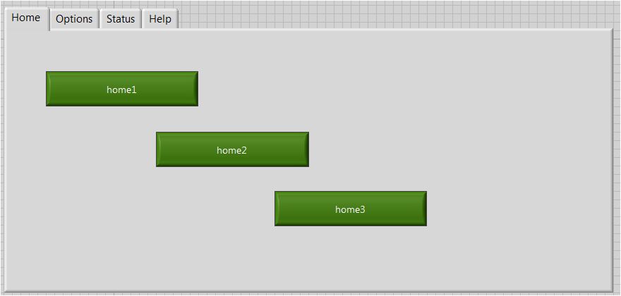
My program has a tab control. In each tab, I have an event structure to control some events.
I encountered some problems. These are:
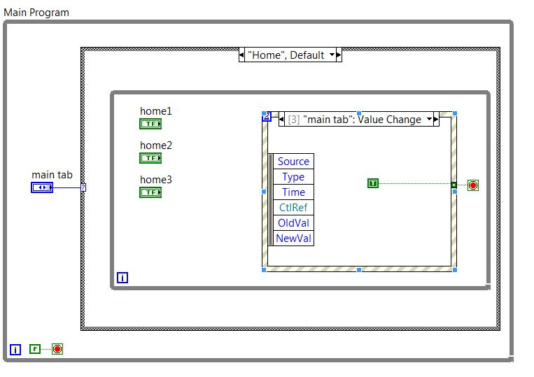
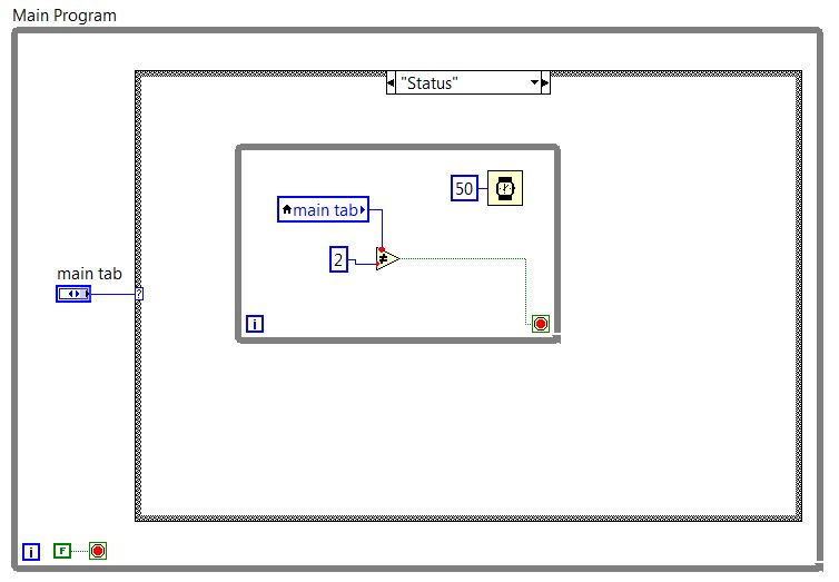
1. in each tab, I set tab as an event control, to altogether from the structure of the event as tab change (for example, the image below). My first problem is that when I change the tabs, in the arch depending on whether my program is entered in the next tab environment, happening at the event: change value to main tab! And gives bad result.
2 - I've scheduled two final tabs as below in the image. I had no routine in these two tabs. Simply, I want when I change the tab, it goes to the next case of the tab control. But when I run the program, it goes to something as busy after one or two changes tab and did not work properly.
Could someone help me please?
Thanks in advance
Baran
Rebecca wrote:
I want to have 4 tabs, each tab having 3 Boolean control.
If in each tab all Boolean control wins 1, a Subvi should be run.
I wrote this code with some time within each tab loop this case hase 3 for each Boolean control. The result is true.
But I think that if I write it with a structure of the event within each tab instead of 3 cases, the cpu load will be lower.
Is it not true?
Make a unique Structure of the event.
Add events for all controls (buttons, Boolean)
When the event is triggeredcheck for active tab control and decide what void / vi to run
It will work fine you
-
major error with the structure of the event
IM under LABVIEW 13.0 PRO
I don't know when this strarted bug happening, but now when I add a business to a structure of the event. Freezes in LabVIEW. I have to close labview with the Task Manager.
It doesn't matter what code I'm working with, even a new VI, with nothing else than a structure of the event.
I tried this on my desktop PC, my laptop and my CPU DAQ.
The error occurs on my desktop and my laptop. But it does not occur on my CPU DAQ.
Whenever I click on add event usually case, you get a popup to configure and add cases, but with the popup error never comes to the top and labview crashes.
Theres no code to share the problem ocured when adding events to the event structure. It happened with any structure of the event, in any code, all the time.
I spoke to an engineer of apllication of labview and suggested to delete the labview.ini file located in the installation of labview directory. I did this and the problem was solved.
Still not sure what caused this to happen.
-
Case structure works is not as expected
Hello all
I have a business structure which does not seem to work there in the State on.
I created the circuit 1st in 1st red slice and it works each led flashes on then off in sequence, but when I try this logic in a case statement (in the 2nd red block) they are all remain lit. What is the way in which the case statement suppose to work? Is their a workaround solution?
Thank you
First of all, you have here a block diagram. A 'circuit' is what you create in the material of electric wires and components with electronic.
All your case structures all work as expected. What you were doing in the upper part is different from the bottom. In the background, each LED is located inside a special case. This particular case only runs when something is true. You have no way of writing a fake to the LED, because if the LED is going to be false, this case will not run. Up there, the LEDS are always in the path of execution, so that they get a value True or False, written for them, as appropriate.
Maybe you are looking for
-
error 2131 on Equium A200 iTunes
Hello My first attempt ever to post to a forum, please nice to me! I know this has been covered before but I do not see how to fix the error. When you try to burn to a disc from itunes, I get error 2131. I have a Satellite A200 equipped of a TST corp
-
TCP connection does not work as EXE
All, I have a RT and GUI from Windows application that uses the TCP protocol to communicate between vi. LabView 2011 PXI chassis Works fine when I run both programs. A program is a graphical interface (uses TCP connection open) to the title of 'My Co
-
T530 - strange problem with RAM after BIOS update
Hi all tomorrow I update the BIOS to the version the most recent (2.58), after this operation, my laptop cannot start: by pressing the power-on button displays only a black screen and the market led... I have tried everything I can do to make it work
-
Windows xp home edition. The computer disconnects as soon as I connect.
This happens in normal mode and safe mode. I just removed a serious computer virus using avg 9.0. I had win antivirus 2010 on this subject. before removing the virus, it was blue screen of death. Now go to the Welcome screen. When I choose a use
-
Connection blackBerry Blackberry App world error
Can't access my BlackBerry App World apparently there is an error with the connection to the blackberry server. How can I fix it?