Timed structure
Hey everybody!
I have a while loop needs to be timed, which means I want to let it run only 10 seconds and if the Boolean connected did not 'TRUE' and I want to quit smoking and create a structure of business that will get if the loop ended within 10 seconds or not (and perform different actions on this basis).
I thought to use the timed structure but I don't really understand how to use it.
You guys (or girls) have any suggestions?
Thank you
If you do not use LV RT (e.g. cRIO, PXI) for this, you should not use a timed loop.
A simple loop using the synchronization features ("Time Elapsed") is the way to go.
Norbert
Tags: NI Software
Similar Questions
-
Timed Structure of the sequence timing error
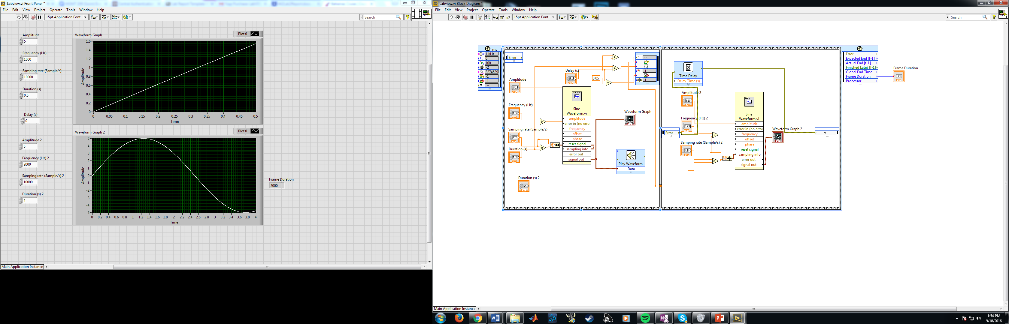
I'm trying to create two RF waves to pulse, at 90 degrees and the other 180 degrees with a second 2 delay after the first impulse. I used this time sequence structure and think that I followed the requrements, but no matter what I change the second pulse occurs immediately after the first. Please let me know what I am doing wrong or if there is another approach to do this. Thank you.
Two things. The delay on the structure of the sequence function is looking for a value in milliseconds, making connections in seconds. If multiple by a 1000.
Second, you're dividing your frequency of sampling frequency and fueling the sinusoidal signal generator. Just wire the frequency.
-
Abandonment of a loop timed - what happens?
LV2013, LVRT 2013
I'm not clear on what happens when you STOP a timed loop, STOP TIMED STRUCTURE vi.
The help says:
"If you try to interrupt a timed running the timed immediately loop loop runs the current iteration and returns ABORTED in the output of the REASON for the data node left."
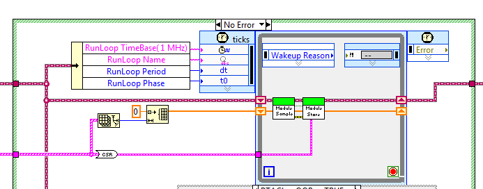
Given the following loop:
I can abandon this loop, by name, by the way.
This cancellation occurs at any time, regardless of this loop is where its cycle.
This loop runs at 10 Hz and takes 1 to 2 mSec per iteration.
1... what happens if the cancellation occurs during the delay? I guess that he wakes up with the reason set to ABORTED. It executes the code inside, or not?
2... Suppose that the loop has already run the vi of the SAMPLE, but not the vi STORE, when comes the demolition. It don't...
( ) 2A... An abortion without running the STORE?
( ) 2B... Run the STORE, browse again with REASON = INTERRUPTED, and then runs the SAMPLE and STORE again?
( ) 2C... Run the STORE, browse again with REASON = INTERRUPTED, then popping out without running again?
3... assume that the loop is located in the middle of the vi of the SAMPLE. What is this VI partially abandoned through?
What throws me is help text: "immediately runs the current iteration and returns ABORTED."
If she abandoned after he woke up normally, then the REASON is already set, so he can't tell me that it's been abandoned. But if she should set the REASON, then it must finish executing the code, browse AGAIN, and then run the code AGAIN, isn't?
Anyone know the rules for this?
I have not tested, I guess based on a combination of documentation and experience in similar situations. It should still run once with the reason set to ABORTED to give the code inside a chance to do a cleaning. If you are in the middle of an iteration, it will end this iteration, then run again immediately. If cancellation is received during the wait, the loop is executed immediately once (stops pending). The last execution will always be reason set to ABORTED, and you never have a situation where the code is suddenly stopped in the middle of execution.
-
Timed loop runs only once with pulse train?
It is a VI that attempts to drive a loop timed with a train of pulses 6608 OR map attached. My timed loop never appears to run more than one cycle. No error is reported. I suspect it's because I'm not set up correctly with NOR-DAQ. Any help would be most appreciated.
WB
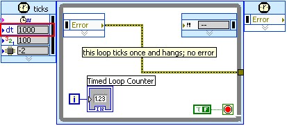
Hi Wb,
Take a look near the timed loop, I can see that the value of dt period is set to 1000. This period is used to scale based on synchronization source units. In this case, the clock contains 0.5 second pulses. Change the dt to a value of 2 has allowed me to see the timed structure to go as planned. See the image below for more details:
I hope this helps. Let me know if this behaves that way even on your system.
See you soon!
-
I need to continually take data but only trend occasionally
Hello. I'm new to LabVIEW and have been given the task of interfacing with a thermostat of LakeShore. My employer wants to my program to recover data continuously, but only to write the data to a file and a graph in a certain period. At this moment I VI data in a loop for which has a time delay inside and set the number of iterations that however many seconds or minutes to pass before it writes the data and then allow him to move on to writing to the extent of the file VI and the graph before returning to loop data. There must be a better way to do it with the timed structures or structures of event or something. My instinct tends to be to use a bunch of while loops for things, but I can't stop them with a button outside the while loop. Can someone help find a better way to go about this?
I would use an Express VI elapsed time that drives a business structure where the "occasional code" is in the real case of the structure of the case.
-
After the search and read a few posts from forums, I understand using the sequence is probably not the best idea?
I wanted to get some advice on the best way to address my problem.
What I want to do:
I intend to use the van der Pauw method and the hall effect to experimentally determine various parameters for a small sample of semiconductors.
Right now, it's a lot of your time to make all of the BNC connections required by the hand that in all the totals to 24 or 48 connections to make.
To speed up the process, I want to use Labview to control a microcontroller to control transistors which controls of the Tower relays who make the required connections. At the same time after each series of necessary connections have been made, a current source controlled by Labview must provide the necessary current, a voltmeter to read voltage. A total of six different sets of four connections to perform and voltage read for all six groups. This must be done twice, but since the equipment creating the magnetic field is controlled manually, I can just run the program twice.
Recently, I learned how to control an arduino using labview and how to control the power source and the voltmeter using labview as well.
So here's the sequence that labview should send orders:
Digital I/o using 6-pin on arduino
1. initially, all pins are attached below.
2. first pin set high, while the rest remains low. This option turns on a transistor making it the first series of connections.
3. the current source is turned on and provides a specified amount of current to the sample.
4 voltmeter measures the induced voltage and stores this as a double or be it in something like a table.
5 current source turns off.
6. second pin on arduino set high, while the rest low and steps 3 through 5 are repeated until all 6 pressure measurements were recorded.
7. the 6 measures must be exported to excel the file or Notepad or other.
8. the same data could be transmitted to something like a different tab in the same program to perform the calculations to find the semiconductor, parameters of the sample.
So now my question on the best way to do these things. I was looking through labview and found what is called a sequence of flat, but according to the forums it's supposed to be frowned upon.
My other thoughts using some kind of combination of loops/case, but I'm not sure how to structure and what should be included or excluded from the loop. Other thoughts are maybe a timed structure. Another possibility is to create 6 different vi and calling it one by one.
So basically the program run, and once completed, I need for each measure 6 voltage, preferably displayed in both a table and saved in excel/Notepad.
SaintsFan says:
So here's the sequence that labview should send orders:
Digital I/o using 6-pin on arduino
1. initially, all pins are attached below.
2. first pin set high, while the rest remains low. This option turns on a transistor making it the first series of connections.
3. the current source is turned on and provides a specified amount of current to the sample.
4 voltmeter measures the induced voltage and stores this as a double or be it in something like a table.
5 current source turns off.
6. second pin on arduino set high, while the rest low and steps 3 through 5 are repeated until all 6 pressure measurements were recorded.
7. the 6 measures must be exported to excel the file or Notepad or other.
8. the same data could be transmitted to something like a different tab in the same program to perform the calculations to find the semiconductor, parameters of the sample.
A state machine with these 8 States (and perhaps some assistance States: idle, stop, start, error, etc..).

Basically a while loop with a case structure (one case for each State) and a State (e.g., enum) variable in a passage that. Look at the design templates provided with LabVIEW.
(A flat sequence is too rigid for this. What happens if an error occurs in the #5 State? It has no way to go to a State of emergency. What happens if you want to stop in the Middle? What If a State fails and must be repeated.)
-
How can I make this faster (more efficient) loop?
IV attached a screenshot of my code. In the books it is said not having 'picture of generation' and "concetenate strings" in the loop, but what can I use instead? Also are there any other changes I can make to this program, to make it faster?
See you soon,.
Sam
Sam,
for a structure (except "timed structures" as the timed loop) of the time, you place the wait function within the frame where the wait is scheduled. So in regard to a loop simply drag it iside the loop and connect a time-out for her.
Looking in your VI, there is always something preventing the VI of work:
-Remove useless (in comparison with the 10) logic including the invalid son
-Connect a digital '10' to the "n" - of the loop in order to limit the number of iterations to 10.
-Change the output terminal of the loop of the piles of data to be "Indexing" (right-click on the tunnel and select "Enable Indexing"). This will create a table 2D channels; Therefore, you must connect the stringarray on table 'spreadsheet of writing file' 2D connector instead of connector D 1.
-Never, really never ever ever work with unstoppable loops in Windows! This already messed up complete systems of tests doing serious damage to the equipment. The only target I'm ok with infinite loops are FPGA and to some extend, real-time targets...
The right approach would be a producer/consumer, but looking in your messages that you posted the last days, I would say that it is beyond your current knowledge of LV...
-
digital output microsecond LED timer
Hey all,.
I'm doing a table of 10 LEDs in a row to form an analog timer to use to characterize the delay of the shutter on a digital SLR. We'll first stage shutter lag on the camera using a method different and well set the delay of the shutter for interior<1ms. i="" am="" trying="" to="" use="" labview="" alongside="" a="" ni="" usb="" 6251="" using="" an="" sc-2345="" for="" access="" to="" the="" digital="" outputs.="" im="" using="" a="" timed="" structure="" and="" a="" timed="" loop="" to="" ensure="" the="" timing="" between="" each="" led="" turning="" on="" corresponds="" to="" an="" actual="" time.="" however,="" i="" am="" not="" getting="" the="" results="" i="" thought="" i="" would.="" the="" timing="" does="" not="" seem="" to="" be="" what="" i="" thought="" it="" would="" be="" and="" i="" can="" not="" get="" the="" timed="" loop="" to="" work="" with="" all="" the="" channels="" at="" the="" desired="" frequency="" which="" would="" idealy="" be="" as="" high="" as="" possible.="" could="" someone="" take="" a="" look="" at="" my="" code="" and="" provide="" me="" with="" some="" insight="" where="" i="" may="" be="" getting="" issues?="" i="" apologize="" if="" i="" am="" overlooking="" important="" information="" that="" may="" be="" needed="" to="" help="" solve="">
~ Aaron
I have no DAQmx I can't be sure. I think that the 6251 has a maximum rate of 1 MHz in order to try to set the rate to 20 MHz should generate an error. For the purposes of test on the rate 1 Hz bit or less. Then you should be able to see the LEDs as turning on and off.
You may also need to set the number of samples to the size of the array. Referring to the size of the array fed to Scripture DAQmx, not the table on the front panel. With the number of samples set to 1, I would expect that he wrote that the first element of the array that is equal to zero. That does not produce a very interesting performance: he lets just all lights off the coast!
Lynn
-
I think that there is a bug in the function RT Set CPU pool assignments (SMP)
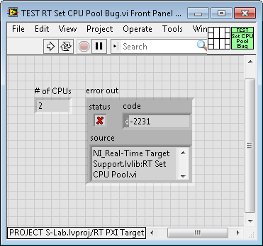
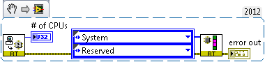
I'm trying to configure Symmetric multi Processing on a PXI controller which has 2 CPUs. I check the number of processors using RT get number of processors (it gives me 2). I have a constant matrix of wire to the RT Set CPU pool allocations function and create an array of 2 elements with system and reserved as the two values (to assign a single processor for my timed loop and the other for "everything else").
It works, which means it seems to do the assignment. But if I look at the assignments of Pool Set CPU error line, it returns-2231, "invalid CPU pool settings. Each pool must contain at least 1 CPU. »
I do not know what that means, or why I am getting the error (I might just "ignore it", but if the error is 'real', which is not supposed to do). The entrance to the Pool Set CPU assignment is described in the documentation as "an array of enumerations, with an entry for each CPU. For me, this means 2 entries, which is what I have.
Does anyone have a rational explanation of what's going on? Is this a bug? The documentation is the problem? I have attached the front (showing the number of processors and the error output) and the (very simple) block diagram.
Bob Schor
Thank you, Bobby.
I reread carefully the Note help "Specifies the Set of processors available for automatic load balancing". Now that I know the 'right answer', I can interpret what is written as planned, but it's not easy!
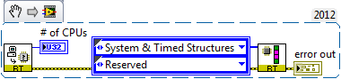
It is also curious that, although the previous example has generated error-2231, if we deleted the error (or wired never error line), function has, in fact, affect the system and Timed Structures pool to CPU0 (I have a few 'real' testing code that shows CPU0 with Structures Timed cycles). Given that the function "does the right thing" even if you specify parameters of 'bad', perhaps it should be treated as a warning, not an error (or otherwise make a mistake of 'real' not assigned to a pool - it also wouldn't hurt to have a less obscure the Error Message, or more explicit "be sure to have at least a CPU explicitly assigned to each system and Timed Structures pools") , maybe in "BOLD".
This code has no error:
Hereby I give you credit for the 'Solution', but I'll mark my answer as the Solution because it has a photo to help readers who are intrigued by the question and our responses.
-
Generation of PWM in FPGA pulses with nano seconds
Hi guys,.
I work with myRIO FPGA.
I have seen a few examples to generate PWM pulses in the FPGA target with the help of timed structures. Timed structures can contain the frame in the sequence structure flat with time control less than 1 micro second (1 MHz).
But I want to generate impulses PWM digital pins in hundreds of nano seconds.
I saw datasheet of myRIO - 1900. It can generate a frequency up to 40 MHz.
I need the pulses on the order of 10 MHz.
Can someone help me how to generate pulses on the order of 10 MHz PWM?
Hi fires,
the FPGA can use "ticks" aka clock pulses for delays.
As your impulses are of the order of 4 ticks, you could use simple statements waiting!
-
IMAQ Vision data synchronization and niScope
Hello!
My task:
-Take photos with a camera (Photonfocus MV-D1024E-160) connected to a PCIe-1427 OR Framegrabber) at a speed about 300 fps in freerunning mode
-Measurement of signals with a digitizer PCI-5922 to kS 500 per second
-Store all the data on the disc
Now I must find the time window of the Signal digitizer exactly at the time the image was taken.
What your concept would do something like that. (I use the niScope and Vision)
I made a few first tests using the:
-Sync starts timed Structures VI
-Use the overall time of start/end of a loop timed as the timestamp
-There is also a line of State microsecond stored in each photo (I could use for the moment)
Last but not least:
-How you realize the DTX200
-I have tryes with securing the data of the image and the digitizer in separate binary files (PDM would be the best option?)
-Would you use queues?
I m happy for each indicator of concept! Just write if you need more detailed information!
Thank you
Tobi
Hi Suse
Thanks much for the advice. After much effort, I arrived at the following solution:
I m happy if you or someone else has any comments thereon (such things is quite advanced for me):
Two VI´s at the same time independent (see attachments)
(A) consumer/producer of image
(B) digitizer consumers/producers
In addition to data I also course start time of world of the loop timed for each data set (afterwords I understand Images signals digitizer using this timestamp)
(A) consumer/producer of image
Appendix A: after initialization of the acquisition of the image (upper left). "I have a producer (top) loop that generates an array of 8-bit image data and the Global timestamp of the timed loop). The loop of consumer (bottom) to remove the cluster and saves each image in a binary file with the timestamp of nanoseconds as file name. Like this I m in images of the camera stream on hard drive at about 150 frames per second at full resolution (1024 * 1024 pixels) and still more quickly at low resolution (with a return on investment)
(B) digitizer consumers/producers
Attachment B1: after initialization of the NOR-SCOPE, I extract (Points per fetch = 2000 for the moment) scanner data and build a cluster with the global start time (and world end time for the tests as well) to new (similar to A). I queue in the loop of the producer
Appendix B2: I Dequeue data in the loop of the consumer and the write (stream) to a PDM file
Stop all the loops after Acquisition and storage I use a notification utility.
Issues related to the:
-Where do you see the bottlenecks in this design (which could slow down?)
-What could be done more effectively?
-How accurate is the overall end timestamp (I want to know exactly which picture belongs to which signal digitizer). I didn t find much info on this Global Times (how are "produced" in LabView?)
-Other reviews, consult about it?
Thanks again!
Tobi
-
My VI is checked several conditions, when true, a Subvi expected popup and wait for my entry (press one of the four buttons), however this Subvi blocks (IE closed without waiting for my entry), so I checked the error out of this sub - VI and he said: code error-808, source:
Timed structure (s): L110126428 What does that mean?
You can do either configuration GUI of the loop:

or you can do it on the block schema by adding an entry to the entry node.

Once again, it's all in the documentation.
-
Change the speed of data acquisition
I record the temperature using a PSC-2120 (cFP-TC-120 + capable). Could someone please explain me how to slow the acquisition of data to make each minute rather than each MS that's for two reasons. First the data file are produced get so large that excel do not all data from a spreadsheet and Notepad can not open them. I had a .lvm file which was more than 700 MB of the day to the next. Second, the data is displayed on a graph when it is saved (left hand on the vi graph), but he is drawn as a variant rates. Sometimes it's every millisecond, others it's every few seconds.
I enclose my VI, but I can't reach my text file is too lig must be downloaded (it was after 10 min data recording)
Thank you
Chaz
Hi Chaz,
Thanks for the post and I hope that your well.
To change the rate of datalogging, you will need to use the timing of the loop. You can do this with a (better) timed loop or with vi timing structure (for example, wait until the next multiple) in the loop (good). This knowledge base article, he explains in detail,
How to set the analog input of my FieldPoint Modules rate?
http://digital.NI.com/public.nsf/allkb/3DCBB324D23FD637862571320066AA7A?OpenDocument
Hope this helps,
-
Structure of the event in timed loop
Quick question on the structures of timed loops\event
What is a good or a bad idea to use structures of event call loops - as opposed to while loops. ? I guess I like the idea of call loops - because you can prioritize them - so if there are some important things you need priority of 100% in the background - but for the user interface, you can configure it to run slower\or run to a different priority level.
I just wanted to check it is not a reason why I shouldn't do that - since all the examples don't do that.
JP
I don't think it's a good idea. Your timed loop can stop waiting for an event. There is no advantage of placing the structure of the event in a timed loop. It is possible to assign priorities to other objects outside of the call loops. For example, you can the priorities given to subVIs. I'm reasonably sure that the structure of the event can work at other priorities if you do not the activities of the user interface. Maybe someone of NOR can confirm this.
But the goal of a timed loop is to have a deterministic periodic job. The structure of the event must be used for asynchronous events. The two disagree with them if they are in the same spot.
-
Sequence structure flat inside the timed loop and execution order
I have some problems trying to implement a flat sequence structure when you use a loop timed on a target of cRio VI
I tried with or without the while loop around the structure of sequence flat, and I also tried to replace the 'Non-deterministic loop' with a timed loop
The problem is that the program seems to run only once, then get stuck somewhere
I am writing a program that performs the following operations as soon as possible:
1. read the Pos_MC of entry on the FPGA
2 send the value of Pos_MC to the VI target (on cRio CPU)
3. calculate a value of output based on Pos_MC with a PID block ("exit PID')
4. send 'PID output' to the FPGA
5 write "PID output" analog output "MOOG".In addition, I want the program to return the measured value "Pos_MC" to a host VI for the recording of data
So that the output of PID is calculated and sent to the FPGA as quickly as possible, I placed a flat sequence structure to ensure that it happens before you send the output to the nondeterministic loop for recording data
Also, I want the digital input 'Stop' to be able to stop the loop deterministic (the timed loop)
I read much more entries than that and the help of several PID and exit, but I rewrote the code for a single entry and exit to make it easier to illustrate
Screenshot of the code is shown in 'target code.png' and 'fpga code.png.
The VI themselves are attached in the next post (cannot attach files of more than 3)
Question 1:
Any advice on how to get this race? Thank you!Question 2:
Is also my correct understanding in that, using this structure, each 0.9ms (fpga loop time) comes the following:
1. the input ("Pos_MOOG") is read on the fpga
2. the production of PID is calculated on the cRio with some delay to computation (for example 0.1ms)
3. the output of PID is then written for analog output "MOOG" in all about 0, 1 - 0.2ms
4. the FPGA program then waits until 0.9ms spent and repeat the processAs opposed to the next pass whenever performing a loop is started on the FPGA:
1. the FPGA reads the input and written on the output (the output of the execution of the previous loop PID)
2. then the entry is sent the cRio, PID output is calculated and sent to the FPGA
3. the new release of PID is maintained until the next time through the loop
Thank you!
PHG wrote:
Thanks for the input guys, any advice as to how I could get the feature in scenario 1?
I still say that the best route is just putting all the logic of the control in the FPGA.
Other alternatives include 1) the use of DMA FIFO sedn data back or 2) use interruptions so that the FPGA code can not read the output level until the RT.
DMA FIFOs are usually very limited, and I would not use them in this situation since I belive said it this code to do for the many outputs.
Maybe you are looking for
-
"back" button does not work in https google search
Search Google seems to have made mandatory https once connected. It breaks the history and behavior of the back button to the results page of google search on the results page. I think it's because google, clicking on a result link, redirects to the
-
When you browse my application management in the settings screen, that I fell on the app already download Swype. I think it's great that it was already on my phone, but I can't use it. How can I use it?
-
LabVIEW can support devices EDDL and how? And it will take all of the third-party drivers? If NEITHER provides support EDDL then please tell me the details of interface hardware and software information and how I implemented it in labview?
-
Help to install a second hard drive in an a6407c
Hi, recently, I ran out of hard drive space and decided to add an additional hard drive. The drive I bought is a "Seagate Barracuda 1 TB 7200 RPM / MIN SATA 3 Gb/s 32 MB Cache 3.5 inch internal Desktop Hard Drive ST310005N1A1AS-RK-Retail Kit. My comp
-
upgrade to VISTA Ultimate after installation of the Home Basic
I had a hard drive crash and when I did the clean install I use the recovery disc for Vista EDITION family Basic. I now have the recovery disc for VISTA Ultimate. The TWO sets of disks are OEM Lenovo/IBM ThinkPad 32 bit system. It is a long shot. Is