Timing in Labview
Hello
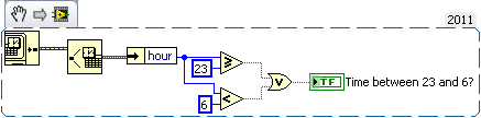
I'm creating an application where I use a set of data for 72 hours, in order to find the best timeintervall to make a certain operation. However, as people tend to sleep at night, it is not very realistic to simply place the operation at the time where it ideally should have been done. That's why I want to set a timeintervall when the operation cannot be (i.e. from 23:00-06: 00).
The problem is that when I try to do (using the timestamp of when the digital palette controls), I also need to specify a date. I used to only are valid for a specific day, but for the entire group of data. Is there a workaround to avoid this problem?
Greetings
Kristoffer
It is quick example. If you do not want to run the operation from 23 hours to 6 hours (I think). The attached example will give high/true Boolean when the time is between 23 and 6, and fake the rest of the time. If this isn't the thing you wanted then explain a bit more so that it is easy to understand the exact scenario.
Good luck.
Tags: NI Software
Similar Questions
-
Loop timed in LabVIEW DLL does not close
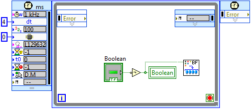
Hello! I have what I think, it is a simple loop timed in LabVIEW that stops after 100 iterations by throwing an error and letting the loop 'stop on error. It works fine when it is executed in the ordinary LabVIEW environment, however, when compiled as a Dynamic Linked Library (DLL) and called from LabWindows it requires me to put an end to execution, rather than going out nicely. As well, it seems to leave the real appeal of virtual Instrument very well and go to the next line of code, but when my function main() in LabWindows is completed it must always be something not cleaned which is the cause not come out well. Any ideas? I tried to add only a call to QuitLabVIEW and that doesn't seem to do it.
Thanks in advance - hoping you will notice an error really easy.
 )
)A photo of the timed loop is attached.
An excerpt from the code of LabWindows:
int main)
{
CallMyLabVIEWDLL(); This line launches successfully and closed the window for my virtual instrument LabVIEW
MessagePopup ("' My Title:", "That occurs after the call to your LabVIEW DLL" "); This popup appears - indicating the call to the DLL has finishedBut after the code has completed LabWindows always shows "running", rather than close.
return 0;
}Why do you use a loop timed in the windows environment? They are best used for real-time environments (not windows) and tend to have more support than the time.
Is there a particular reason, a while loop will not work?
-
Violation of timing in labview fpga
Hi Member
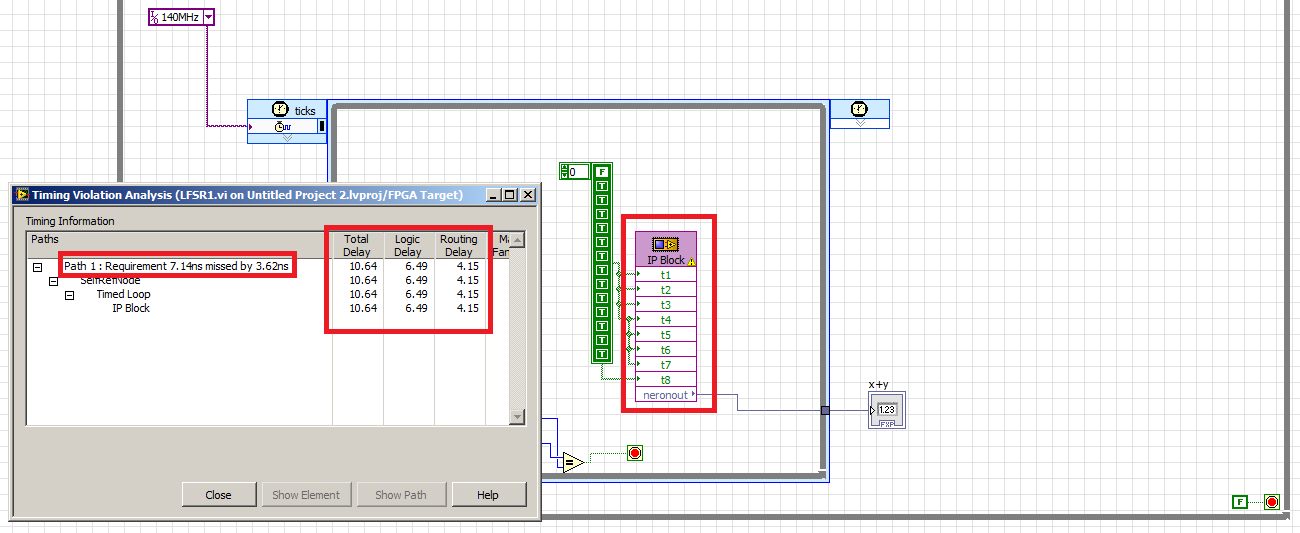
in the figure below you can see a time violation was happen in my IP integration
the problem is to know how to calculate the maximum frequency of the numbers appeared in the Red block?
I'm trying to connect to 150 MHZ, violation of 140 MHZ time also appear!
What is the maximum frequency of work for this IP block?Delay of logic is the delay by real choice tables, DSP blocks, etc. The delivery time is the time between the logic of 'true '. the delay between the logic blocks, including the time to go through the switching matrix. Generally, you cannot reduce the delay of logic without having to rewrite your algorithm, but you can reduce routing delays by inserting records in order to let the tools move logic on the chip.
And you've stumbled upon one of the great mysteries of the use of an FPGA. Sometimes changing the clock frequency just cause tools to generate a different code that works better. In your case, it seems that the tool could do better and hit 100 MHz. With your original 140 + MHz tool understood from the beginning that it would not reach this rate then it stopped soon before making other optimizations, showing you as well as he guessed couldn't make it around 90 MHz.
-
Why is-DAQ-200714 fatal error?
I'm having a problem where a system that works well for a while, with a good margin (rate of 1 kHz loop, 300uS PCL loop duration), suddenly throws the error-200714 and stops. I have the filter DAQ errors on, and it's performance that are linked, so why this closure of the system rather than increment on behalf of HP?
Thank you
The explanation of the error is "Acquisition has stopped because the driver could not transfer the data from the device to the computer's memory rather quickly. This was due to limitations of the computer system.
Reduce your sample clock rate, the number of channels in the task or the number of programs on your computer that runs at the same time. »
Hello Stephen,
You get this error is because the program is not keeping up with the sample clock.
I recreated this (outdoor VeriStand) by running the example of shipping single HW-Timed Point LabVIEW and increasing speed until I got this error. I actually got error-209802 several times before to do-200714. The first error is recoverable and I could ignore it and continue, the second execution stops when it is thrown.
Error-209802:
«DAQmx wait the next sample clock detected one or more examples missed clock of the device since the last call to wait for the next sample clock that indicates that your program is not keeping up with the sample clock.»
To remove this error, slow down the sample clock, or else modify your application so that it can follow the sample clock. Alternatively, consider conversion errors affecting true property warnings and then assigned to the case of the appropriate warning. »
Error-200714:
"The acquisition has stopped because the driver could not transfer the data from the device to the computer's memory rather quickly. This was due to limitations of the computer system.
Reduce your sample clock rate, the number of channels in the task or the number of programs on your computer that runs at the same time. »
Based on what Jarrod mentioned above, the original error might be filtered by VeriStand judging by the part highlighted in blue to the first error. I suspect that the error-200714 is fatal because of the part highlighted in red above; the acquisition has ceased.
If you monitor the DAQ system channel error, you see error-209802 so? Slow down the rate PCL resolve these errors?
I hope this helps!
Trent
-
poor performance analog output (error 200018)
Hello. I have a 6124 SMU Board with controller real time SMU-8102. the Council is speced to MECH 4 analog outputs. / s (one lane), but I have problems to operate at anything beyond about 500 kech. / s. I enclose my example below program. If I put the rate at 500 k, it works. If I put 1 m, it does not work and I get the error 200018 (DAC conversion attempted before Conversion data were available). I use the DMA transfer.
I also tried to increase or decrease the number of samples written by loop (between 50 and 300) and using a loop timed in labview real-time. That essentially gives the same result (sometimes I get error 200016 instead, "exceeding accuracy onboard device memory").
Because the controller is a dual core controller that do literally anything else (what I showed is the whole program, nothing else running), I don't know that I have some setting wrong software. I can't believe that this controller is unable to deal with this card. Does anyone have any suggestions on what I might try?
Version of LabVIEW is 2010 and DAQmx version is fairly recent.
Ok. I thought about it. Here's an interesting fact. At the rate of 1 MECH. / s, tries to write to 4096 samples each microseconds 4096 works perfectly well. But any attempt to write to 4095 samples fails! 4095 course is 2 ^ 12-1. It seems that DMA was running only transfers of 4 k at a time, so when he got 4095 samples, he was waiting for a sample more start the transfer, but at the time where he got this sample, it was too late. I changed DataXferReqCond property for "almost complete." Now, I can write about 150 samples at a time instead of 4096. Greatly improved!
Moreover, it would be really good to put in the text of the error message for the error 200018 so that others live several days tearing their hair like I did...
Thanks for the help
Daniel
-
Fastest time expected update - NI 9265 current of output
I use an output module current 9265 with 9174 chassis. Basically, I want to read in a text file, analyze a value to a certain dt (at the present time, I am 20 Hz) and writing a value to the card, which will control a valve. Break down: adjustment points (1) read a 4-20ma 2) output the value of EI file to a certain dt for each iteration in the while loop. Can I expect this system to be close to 20 Hz? I need my timing to be very close, but I understand that by using a Windows system (Windows 7) will cause the jitter in the system and avoiding the near-perfect. Thank you.
Hello Mr._Bass,
The NI 9265 updates its output values each 9.5 US, that only calculates over 100,000 samples per second. Therefore, the hardware itself has the ability to maintain this speed. Depending on your system and the amount expected from the jig, this number can vary quite a bit depending on your machine. If you have typical tasks such as antivirus, firewall, or any other thing that Windows is running in the background, jitter will increase. On average, the amount of jitter in a windows system is the order of the hundred nanoseconds, but can vary considerably. Outputs at 20 Hz will be an update with a period of 50 000 (0.05 s), so even if your system jitter is high and about 50 US, it would affect only your calendar of 0.1%. Please keep in mind that these amounts of jitter are estimates and may be not accurate for your system.
If your application must be very closely controlled, and you see higher levels of jitter that your system can support, there are steps to take to reduce jitter. The best way is to use LabVIEW Real-time, but this option would probably a bit of review to implement. I recommend just using a timed in LabVIEW for Windows hardware output operation. Because the jitter occurs in the operating system, you can write your data to the physical buffer of your NOR-9265, where the sample clock will have no interference of Windows. "To see the difference in hardware and software timed operation, launch the Finder for example OR by browsing in LabVIEW for Help" find examples. "" "Then select hardware entry and exit" DAQmx "analog generation ' current. You can see two examples, Gen Mult current updates-Int clock VI and Gen Mult current updates-SW Timed VI. The main difference between these two screws is the use of the VI DAQmx Timing for timing of setting material being controlled. More information on the implementation of operations of timed material are available here: http://www.ni.com/white-paper/2835/en#toc5
I hope you find this information useful. If you are concerned with the jig in your system and need an easy way to measure and control, you might also look at using the NI LabVIEW Jitter analysis tools. Good luck with your application.
Concerning
-
Blackfin Timed loop works in VDSP ++ with .dxe but not in Labview
Hello
I have a loop that is timed with a period of 4ms that turns the LED on and.
My oscilloscope shows that the LED * s are enabled for 5ms, that turnd off for 45ms, enabled for 5ms, that turnd off for 45ms,... and so on.
If I load dxe file in VDSP ++ all the lights blink every 5ms.
I use LV integrated 8.6 evaluation
Problem solved
Source name: 1 MHz
Priority: 27
-
Acquisition of data using the single cycle timed loop in labview fpga (7833R target)
Hi all
I want to acquire data of input analog of a generator using the loop of the timed cycle and DMA FIFO funtion. I want to use the acquired data to act as a process for my PID control variable. Can the attached code perform the goal? I'm skeptical about its features. Advice or suggestions please.
Kind regards
Opuk
The SCTL does nothing for you here. Just remove it and write directly from your analog read the DMA write.
And on the side of the host, you must move the Run method for before the loop.
You should also consider to the PID in the FPGA. PIDs work best in a deterministic environment, and you get more deterministic than on an FPGA.
-
why no loop timed in the mac version of LabView?
Anyone know why there is no call loops in the mac version of Labview 2012?
In addition, we know if or when it will be available? Cause its extremely difficult generating multiple signals at different rates to a high percison with her.
I'm sorry if this has been before, but I couldn't find it.
MVidal wrote:
Altenbach says:
Requiring you to use a Mac?
Well, in my case, I'll ask "which forces to use the other plataform? '...
It may be workarrounds to resolve this problem in a particular application, but what I think about the feature of LV in general, that if TimedLoops exists (even on Windows), I don't see why LabVIEW provide in other PC platforms. Not difficult question is to develop, which is NEITHER job.
That's why we use (and pay) tools such as LabVIEW, do not worry to solve the intrinsics. At least, that's how LV has been sold for me.
You are replying to an old thread. I doubt that the original poster will benefit him has 1 post and has not been connected since December 17, 2012
You can start a new thread to discuss the concerns you express.
-
How can I set up a timed loop to run at the entry, rather than waiting for the first time in delta?
If my delta time is 10 seconds, I get my first run after 10 seconds. I would like to run the loop when he entered at the start (0 seconds) then wait every 10 seconds after that.
Thank you.
The first iteration of a loop, a loop's iteration 0. This will not change to the 1 iteration until the next iteration began. It is the expected behavior. Whatever it is inside the loop will run immediately but the iteration count increments until the next iteration begins.
-
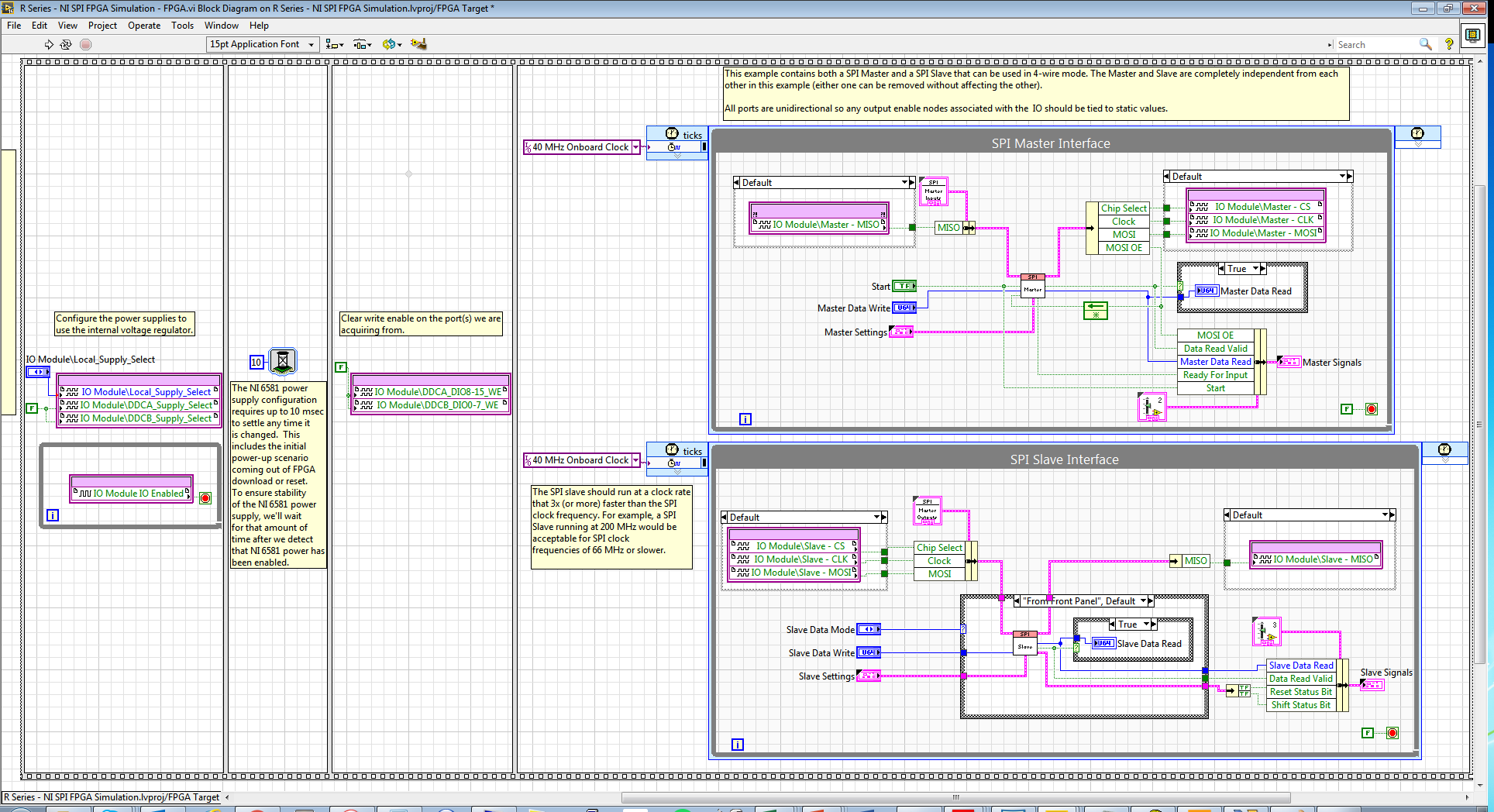
LabVIEW FPGA SPI accident - SPI OR IP address for example - R series OR
Hello
I am trying to run the series R - sample project NI SPI FPGA Simulation.lvproj that comes with the SPI IP OR on a real FlexRIO FPGA SMU-7976R target with an attached digital adaptation NI 6581 B Module. The example is for a PCIe-7841R but I wore during my target FPGA, follow these steps and made additional changes to try to make it work with my set-up. I learned that FlexRIO FAMs CLIPs do not work with nodes in office had so I know I can't simulate the project originally planned so I will try to use FPGA to e/s node host side (open FPGA vi reference) to implement the actual hardware.
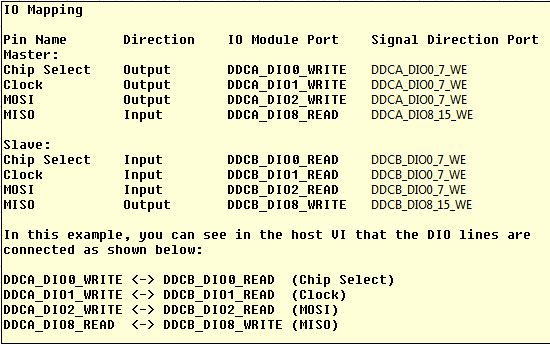
My first question concerns my configuration of the adapter module e/s and selection. I added the IO Module (NI 6581 B: NI 6581 B channel) for my project and selected the channels as shown in the table below. I have a real physical hardware connection as described below using two NI SHC68-C68-D4 cables and a break-out Board.
I changed the names as well:
I selected these DIO channels because I wanted the DDCA connector to be the master and the DDCB connector to be the slave. In addition, in this CLIP every eight channels of i/o has a write enable signal. I have not used the Port configuration because I needed 4 available DIO channels and I saw DIO0-3. Is my logic of selection of channel vs correct Port here?
Following the same strategy that examples FlexRIO/NI6581B, I changed the FPGA.vi to include initialization outside of timed loops:
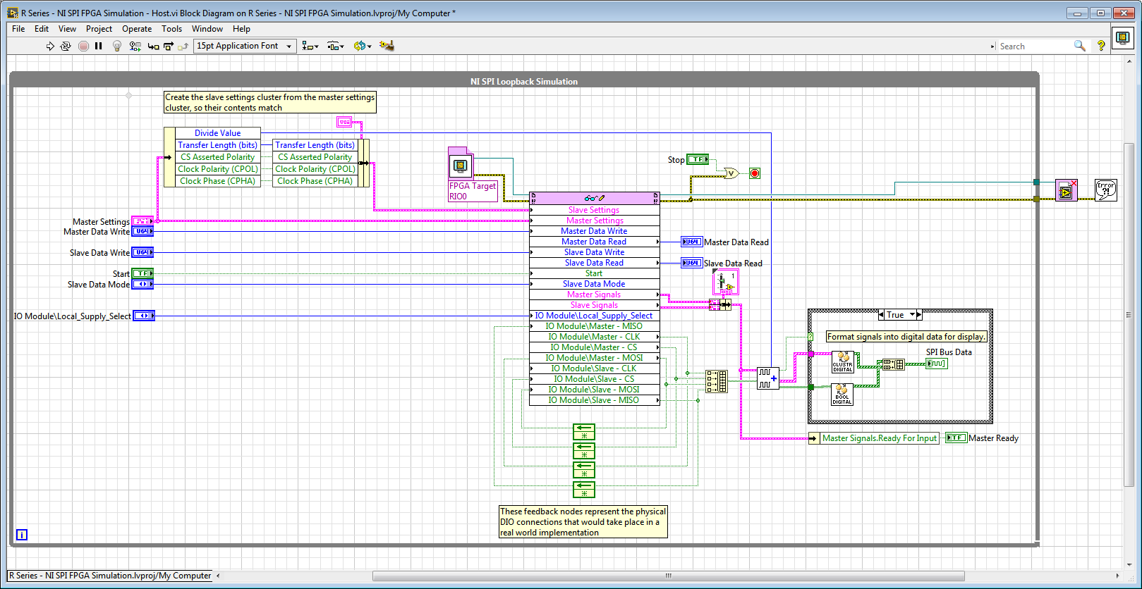
And in the Host.vi I have a node reference FPGA and wired loops of feedback accordingly:
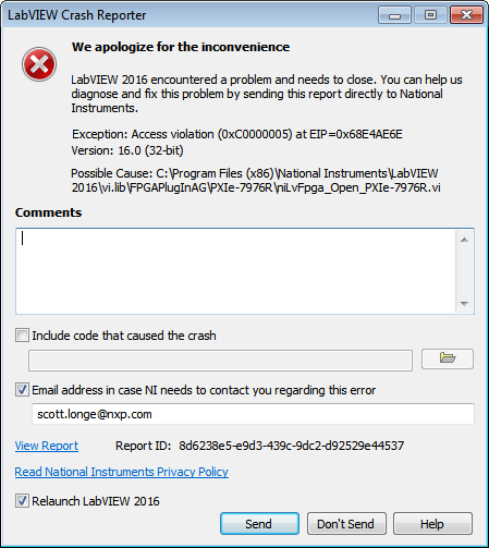
When I compile the FPGA and try to run Host.vi LabVIEW inevitably crashes with Crash Reporter below and must restart:
Does anyone know what I'm doing wrong here? My guess is that it has something to do with the CLIP/IOModule. Any help is appreciated.
Thank you
Scott
Hi Scott,.
I suspect that the problem might be related to the fact that your node open FPGA VI reference is in the while loop and trying to open a new FPGA reference at each iteration.
If you move outside of the while loop, it does not solve the crash?On channel vs port question, your logic seems reasonable to me, but I recommend to try it since this feature could depend on device.
-
USB-6501 - impossible to find a basic example of Labview
Hello
I recently bought a USB-6501 card and I used it in my own succesfully end and C++ programs using the DAQmx drivers.
Then I tried to move to Labview 2009 (I never used Labview) so I looked for a simple example.
I tried to boot from the example 'interactive Control Panel' (http://digital.ni.com/public.nsf/allkb/AF0F31EE5D2AD23F862573140009D7C2?OpenDocument).
I had to install the 'DAQmx Base' for him to start, as described in the previous link. now it begins (before Labview attempted to get a few missing .vi) but I get a message "error 200220 occurred at an unidentified locatio.
Then I realized this example is 'old' (as explained here: http://forums.ni.com/ni/board/message?board.id=170&thread.id=209247), and it is suggested to look for a new one in example Finder ' entry-level equipment / output-> DAQmx-> Digital measurement (or generation)-> read Dig Port.VI.
I tried, but along the way ' entry-level equipment / output-> DAQmx-> "only a folder named"Analog Measurement\Voltage"exists.
Also in the search for 'Reading dig Port.VI' does not work.
I've already spent many hours in this research and tent and the fact that I am not able to find not even a basic example, it is quite frustrating and it is making me give up the idea of using Labview.
Please can anyone give me any suggestions where find/download an example simple and minimum to use my USB6501 in Labview 2009?
Thank you
Scipione.
First, install DAQmx Base was a mistake. Uninstall it and then install the Driver-OR-DAQmx. The driver must be installed after the installation of LabVIEW. After installation, make sure that the device is listed in MAX under "DAQmx devices. If it is not, your installation is still not correct.
To search for example LabVIEW, see help > find examples. Under Input and Output hardware > DAQmx, you will find the digital generation and numerical measures. You have to look at the simple, timed software examples such as read write dig Chan, writing Port to dig, dig chan, reading Dig Port. You also have the option to use the DAQ Assistant.
-
Hi all!
I have a question about the calendar with the DAQmxbase functions. I have the task to save data with a sampling frequency static (it will be greater than 100 000 points per second in theory) and I need to display a writing data to the file in real time. So my idea was to put the sample clock to whatever the desired sampling frequency (lets say 100 000 at the moment) and I would have a loop of standard state machine (just a while loop with shift registers and a case statement inside) to collect data and write to the file then to decimate the data to display to the user. Each of these iterations, the amount of data read would be one-tenth of the sampling rate so I thought I could count just iterations until I arrived at the sampling frequency * 10, which would be the total number of hours. Unfortunately, after the execution of this program for a desired 20 minutes to 50,000 points per second, I noticed that the iterations had invariably longer over time, but it was so small that I didn't notice when I tried for 3 to 5 minutes. Is that what this has to do with the decimation of data slow down the program because we need to reallocate the array every time or it has to do with my way of thinking wrong in the way of our recordings of tension time?
Information
-LabVIEW 2014
DAQmxbase - package used
-System MAC OS X
- NI USB-6211
Needs
-L' sample rate > 100 000 points per second
-record for a specific amount of seconds by the user
-written in the file and displays the user data
Problems
-While the iterations of the loop are run 0.1 of a second making the program more continue to record the tension longer than expected
Please, if you do not understand or I forget important information please let me know!
1 State Machine is NOT good architecture here. You must keep this look DAQ run fast enough to track data in data acquisition. Use rather a producer/consumer. The idea here is that you have parallel loops that make the data recording and processing of data and let the DAQ loop to just read the data that it is.
2. in windows calendar is not reliable. Do not trust it.
3 use the configure DAQmx Timing (assuming that there is no in the DAQmx Base) do DAQmx data stream into your PDM file. It's one thing less worries and it is much more effective would you be able to do.
4. If you follow my advice in (1), then you should read a certain number of points for each iteration of the loop. Let's say 10kS. Therefore, each iteration of the loop will be 100ms. But for your decimation, you take all 10 samples. There is a simple decimate 1 D table that you can use to make it easier on yourself.
-
Reference clock synchronization and clock of sampling (not LabView but Daqmx, Sync and C)
Well, I found an example that resemble what I wanted... in LabView: http://zone.ni.com/devzone/cda/tut/p/id/9308
Now the question is all about timing of the timestamps and sample:
Here is a list of ficelleStringString ficelleT of what I called...
DAQmxCreateTask
DAQmxCreateAIVoltageChan
DAQmxSetRefClkSrc (used NISYNC_VAL_CLK10 = "PXI_CLK10")
DAQmxRegisterEveryNSamplesEvent
niSync_init (used a PXI-6682)
niSync_SetAttributeViInt32 (used Terminal = NISYNC_VAL_PXISTAR0 and NISYNC_ATTR_1588_TIMESTAMP_BUF_SIZE = 3000)
niSync_CreateClock (used Terminal = NISYNC_VAL_PXISTAR0)
niSync_EnableTimeStampTrigger (used Terminal = NISYNC_VAL_PXISTAR0)
Now this list makes me able to create a timestamp every time the clock triggers a RISING edge...
Now how to synchronize these timestamps are useful for my sample? (I mean I need to sync my calendar with the PXI_CLK10 card) because for now prices will not match the sample rate.
ALSO... a little weird...
some of my cards will accept DAQmxSetRefClkSrc but others must use DAQmxSetMasterTimebaseSrc.
Now I can't use DAQmxSetMasterTimebaseSrc with PXI_CLK10... no idea why...
So, how did I would synchronize THESE cards...
Alright I could totally be wrogn with my approach, but I'm new with stuff of OR and using C isn't exactly the best documented piece of the NC.
Thanks in advance,
SEB
Thus,.
We have the same clock sampling for all of these devices, but we are not PLL'ing with the card of the S series, we cannot guarantee that they will all be in phase. However, given that all of these devices would be based on the same reference clock, we would not drift when we started the task. Would this work?
An alternative is to use the new X-Series card, which can also do a simultaneous sampling, but I don't know if it is feesible within your application.
-
Then as the loop timer Timing vannes_ouvertes. Elements
I would like this while loop to iterate through every second. But it seems that he doesen't recognize the loop timer. What's wrong?
Just found the article to help talking about it: Debugging of FPGA screws using Mode Simulation (FPGA Module)
At the bottom, it says:
Understanding simulated time on the host computer
If you use some FPGA resources and you run the FPGA VI in simulated using I/O simulation mode, the resource uses simulated time rather than real time. Simulated time could be faster than real time according to the number of events that occur during the simulation. For example, if you add a waiting VI (simulated time) for the schema and set the timeout to 1000 ms, LabVIEW does not attempt to delay a second of real time. Instead, LabVIEW delays as long as necessary before performing the next action scheduled in the simulation.
The following resources are using the simulated time on the host:
- Then the loops
- Single-Cycle timed loops
- VI of waiting (simulated time)
- Loop timer Express VI
- Number of cycles Express VI
- FIFO, except DMA FIFO
- Wait on Occurrence with Timeout based on ticks
- Interrupt the VI, during her wait until this that clear is TRUE


Maybe you are looking for
-
NB100 - how to install Windows 7 without CD player
Hello. I was wondering if anyone knows how to install Windows 7 Pentecost on a CD player. I have an external HARD drive.Is - this posibel to make an image on this one to boot from?
-
Qosmio G20: Question on lack of cooling
How many people have had 2 hardware failures in 18 months? Including a cooling failure. Very inconvienent when in the middle of an ocean!
-
If I have two different data sources, the two of them have some of the same information, how compare automatically, and get current data on both files by creating a new file with this information?
-
When I tried to log in it freezes for a while, then he said "signing into Windows Live messenger failed because the server is temporarily unavailable. "Please try again later".Error code: 8e5e0211
-
No function address in Outlook?
I have to type the address manually whenever I send mail from my account. There doesn't appear that there is an address book (which is probably the cause). It could have been a problem in the conversion from WLM to Outlook and I don't know where I ca