Transformation of signal-to-symbol (FXP enum)
Hi guys,.
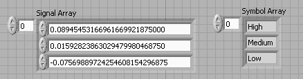
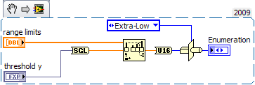
I write an application where I will have a table of temperatures in FXP (from a reading of FPGA) I need to change to a representation of the symbol ("HIGH", "MED", etc.) according to the interval in which the value is located.
That is to say;
I have implemented this in the following way;
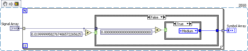
It works for this simple example, but if I had more than 3 States in my Enum code would begin to be quite annoying.
I would like the code to be able to manage;
- Different limits for different items in a table of Signal; 0.2 could be "MED" at one point but "HIGH" for another.
- Also be scalable for Enum values ~ 10.
Can someone point me in the right direction?
Thank you very much
Pete
Tags: NI Software
Similar Questions
-
Is it possible to predict the shape of the signal at position B by the measure in a position?
Hi, I need to know the shape of signal and position phases B, but I have only a single antenna to a position, which is of the form 1 m B. The signal is a source far away. I think that it is possible to predicte it.
Like this: first transformation the signal received at A time in the field of fourier-domain, then caculation phase changes of the components of frequency between A and B. After that turn it into time domain, it should be the series of signals to frequency B.
I simulation Matlab process, but it seems that he has a problem. What is the problem with this method? Are there methods to achieve this coming? Any response will be appreciaged.

If your antennae are in free space so that you can assume that you have not all paths multiple problems, so it shouldn't be too difficult to predict the relative phase between A and B.
You should know the angle between the line from A to B and the B line to the source. You need to know the wavelength. You need to do a few trigonometry. In the simple case where all three are collinear phase shift is 2 * pi * (spacing of A - B) / wavelength. For the other angles, you will need to calculate the appropriate triangle.
If the signal has a complex modulation, especially if it signals a wideband, there may not be any simple way or simple to calculate the phase shift.
Lynn
-
Is it possible on board animate through code to set a value of transformation of timeline?
Is it possible on board animate through code to set a value of transformation of timeline? If this isn't the case, it would be a great feature. For example, I have a symbol that I'm animated to look like, it's jump using the timeline. I would like to use the code to turn a bit randomly the symbol at the height of the jump before she comes back down. I tried sym.$("element").css ({"transform":"rotate("+randNum"deg)"});}) in a trigger on the timeline, but it seems that my code gets overridden by the transformations of chronology of Edge.
It would be cool to have a user interface to say choice a value in a range for this keyframe. Or if there is a way to do it through code that had to be cool.
If I understand correctly, you want to do animation of the jump to animate and change rotation according to your logic.
You should take this approach.
1. Add a handler for "Timeline.update".
2. in the Manager to obtain the current transformation
3 merge your rotation with the current transformation
4. set the transformation merged as a symbol. $("element") .css ({"transform":...})
You will find this useful
-
How to move a symbol + reference guide
Hello
I am sorry to be a noob. I installed Animate a week ago and have a prototype in 3 days, so I'll just ask:
(1) how to move/transform/translate a code symbol? The editing, the symbol itself, or another symbol would work. Leave in the symbol, I thought I could do something like:
SYM. CSS('left',100);
but it does not work.
(2) is there a reference guide listing everything you can do in a symbol? I see examples such as:
SYM. Play();
SYM. Hide();
SYM. Animate ({opacity: 0}, 500);
but I can't find a list of all my options.
Or is it something I can do with javascript or jQuery?
Sorry again for giving and asking.
Thank you
-Sherry
And Sherry to move the symbol to say click on symbol, you can use code like:
sym.getSymbol("Symbol_1").getSymbolElement (true) .stop () .animate ({"left": "= 30px"});
Add this to say the action of Symbol_1 click.
Hope that helps!
Kind regards
Soline
-
I'll start by saying that this issue could be in my head.
I've updated to el capitan yesterday and I noticed this morning that when I play normal audio at a reasonable volume my two speakers vibrate slightly. I don't remember what is already a problem before.
I was wondering if anyone could tell me if it is normal to feel slight vibrations on the retina pro 15 "pregnant?
Thank you.
I assume you mean "while sound comes from the speakers ' and not otherwise.
All speakers vibrate when they work. It's physics to transform electronic signals into sound audible. I realize, you don't ask a question of physics, but it is hard to tell from your question if you mean normal vibrations coming speakers when they work or there's something happening feel you is unusual.
I still feel the vibrations of the speakers when my hands are on the keyboard of my Mac laptop (a 15 "retina MBPro, a 13" Air MB).
-
How to connect Equium A100-306 to HDTV?
Hello
I was wondering if it was possible to connect my Equium A100-306 to my HDTV using a VGA cable component? The laptop has the chipset intel 945g.
Thank you.
Hello
You cannot convert only a RGB (VGA) signal to component (Y-Pr-Pb), since you will need a converter that transforms the signal vga to this component.
Which means that you also a converter for cable that could be very expensive. But if you've got components that you should be able to display an image on a device that has entry components. Don t think you will be able to run the HD-ready or full HD on a HD TV, since a HD signal requires an HD port on your computer and a disk hard taking supported system with better graphics chip and then a chipset intel.
Welcome them
-
Scaling of voltage of the thermocouple before voltage to temperature conversion
Hello
I have a module of data USB-6211 acquisition entry with Labview 8.6, and I will measure temperatures using a type R thermocouple. Because this thermocouple voltages are very small (about 0-20 mV), I'll use an external amplifier (50 x gain) to transform the signal to 0-1 V, then read the entries using the module of data acquisition.
At this point, I can divide the signal by my (x 50) gain and use inverse polynomials for thermocouples of type R (published online: http://www.omega.com/temperature/z/pdf/z198-201.pdf) to convert pressure into a temperature.
However, I noticed that Labview has built in thermocouple modules. There is a stage of creation of task, and the task is sent to a module that allows me to specify the thermocouple type, value CJC etc, then a sample clock, then a sampler with analog wafeform (see below). I would use this structure, rather than coding in polynomials. However, I can't find a way to divide my my (x 50) gain input voltage in order to give the thermocouple module reasonable voltage values.
Is there a simple way to do this, or I'm better just a coding in polynomials?
Thank you!
Amplify the signal, read the voltage, then divide by 50.
No need to code polynomials. Search for pallets for the Subvi convert Thermocouple Reading.VI
-
Encoder FPGA Crio SSI Protocol
Hello everyone
Everyone works with encoder SSI and Crio FPGA Protocol? I wrote a simple program that try to apply this Protocol on Crio FPGA, but I get the chaotic data. I use a TTL-rs422 converter to transform (422) signal at the TTL for Internet signal high speed digital NI9401. Could someone help me? any suggestion?
Thank you
Francesco
Hi all
I solved my problem. I am able to read the angular position of an Eltra encoder with SSI protocol using labview FPGA.
Thanks for all the help
Francesco
-
Setting up an audio I/o buffer continues
I'm relatively new to Labview and run to 2 problems that I can't solve. If anyone can help, that would be great.
I am creating a VI using the sound card that receives an audio input of a generator of sinusoidal signal (plugged into the mic port), transforms this signal in frequency and uses the output frequency a sinusoidal signal of a slightly higher frequency
I started using the example of e/s simultaneous VI and changed to my needs. (see annex VI) I'm using Labview 8.5 on a Pentium 4 3.0 Ghz PC.
I get 2 errors, is that your measuring device measures a signal Inf and means the Niquist theorem. I have a sample rate of 44100 Hz and 4410 samples but a contribution of only 100 Hz sine wave. I paired the sampling rate and samples at a ratio of 10:1. I'm sure that isn't true. You have any suggestions of best on the design of the buffer?
Also, I sometimes get an error message about the read.vi of sound entry "a task must be run to perform this operation."
In this case, I guess I've just been lucky. You should do something, like I did here http://forums.ni.com/ni/board/message?board.id=170&message.id=399671&query.id=277879#M399671
In this way the moment then you read the sound card is not so important. The buffer will prevent dataloss and error. If you get overrun memory buffer the card its task ID will become invalid if I remember correct. Like you, I struggled with the Labview sound system. But now it works fine. At least the requested Party. The exit part have I fixed it with a work around. A way that I've discussed here http://forums.ni.com/ni/board/message?board.id=170&message.id=403131&query.id=279026#M403131 and here. You can also use a free software for audio output. It's called waveio. You can find it here http://www.zeitnitz.de/Christian/index.php?sel=waveio. It works on XP but I don't know if it works on Vista. With this software, you can have up to four output buffers, and the clicks will be gone. Try stamps how much you need. I think that 2 should work fine
-
How to set up my new LCD TV as a monitor double (extended)?
I got the splitter VGA of Radioshack and hooked up to my new LCD TV but it works as a mirrored display. I want to use it as extended display. How can I do this? Customizing the control panel shows as a single screen. I can only see responses on laptop but I had a desktop PC. Thanks for sharing your knowledge.
Given that you tell us exactly which product you have purchased, my best guess is that the splitter you bought is not really a video display device but a splitter that transforms a signal of monitor in two. In this case the two screens will be duplicates and there is no way to force them to become different views. You need a real display adapter that provides its own signal to do so.
"PhoenixKim" wrote in the new message: * e-mail address is removed from the privacy... *
I got the splitter VGA of Radioshack and hooked up to my new LCD TV but it works as a mirrored display. I want to use it as extended display. How can I do this? Customizing the control panel shows as a single screen. I can only see responses on laptop but I had a desktop PC. Thanks for sharing your knowledge.
-
Hello
I am trying to deploy a UC520/SPA8000 pour usage of 3 DECT phones.
I followed the documentation pour a SPA8000 with UN UC520 Integration
My DECT phones come calling to the outside and to internal phones but on the other hand I can't call my DECT internally I falls directly on the e-mail.
If I turn off the messaging that rings busy.
I've done the same Deployment at United Nations another customer without problem.
The difference is that the previous customer USE of T0 and LUN there use a SDSL/Sip connection at OpenIp.
Would you have an idea
Thank you
Gregory
Hi Gregory,
The only thing I can tell you, I did once a migration of a CME that turns on a 2801.
On East past two two T0 to a BIV Orange that virtual the T0 emule (it's the Orange room router which transforms the signal T0 en IP pour out their voice network).
When we did the rocker we had trouble with incoming and outgoing calls.
It turns out that we have the add commands on the 2801 BRI interfaces:
interface BRI0/0/0
no ip address
basic-net3 ISDN switch type
ISDN point - to point-setup
ISDN incoming-voice
ISDN k 7
ISDN send-complete
Info-transfer-ability of outgoing voice ISDN 3,1 kHz audio
ISDN tei static 0
Idem pour interface BRI0/0/1
Hoping that cel can maybe help you
Greetings
Benoit PETRY
-
I am trying to install a data provider defined using csutil user file. I can install the UDV using csutil correctly, but when I look in "interface configuration" GBA the new UDV is not displayed. The command I use is: "csutil - addudv 7 symbol.ini" and he tells me he has successfully installed. I'm under ACS version 4.2, this is my VSA file:
[User Defined seller]
Name = SYMBOL
IETF Code = 388
VSA 1 = SYMBOL-AUTH
[SYMBOL-AUTH]
Type = integer
Profile out =
The = SYMBOL-AUTH-Enums enums
[SYMBOL-AUTH-Enums]
1 = monitor
2 = role of Helpdesk
4 = Nwadmin role
8 = Sysadmin role
16 = role of WebAdmin
32768 = superuser role
Anyone can shed some light on this?
Have you tried to reboot the ACS? Also you must add any device in network configuration using the VSA.
Now, it should appear in the configuration of the Interface.
Kind regards
~ JG
Note the useful messages
-
Eraser tool will save the day?
Hi, I have a background image for the static most of a photo of the track with a model posing for a few different ways like the paparazzi surrounding cubes flash go off. Flash anime model poses and flashes of random sequence.
If I import rough edges of versions of poses and flashes of the model, then use the Flash CS3 Pro BREAK APART command to better clear/feather the edges, I wouldn't be able to those on my background layer and save a ton of space by converting the background image to a symbol for each frame? In addition, could not also transform changes sharp feathered symbols as well, to save even more space?
My current problem is that I imported about 20 copies the same graphic background with the laying of different model and the locations of the lamp flash with layers, and it made my HUGE file. Please let me know if Flash can do. Thank you!
First of all, p ' shop, delete the background - there are several tools for this (lasso, Eraser, etc...).
Then export as PNG-24 format. I suggest Googling or get yourself a good basics of photoshop book.
Personally, I like how to cheat in Photoshop (Steve Caplin) or Photoshop Studio Techniques (Adobe
Press on). There are TONS of books P'shop then visit your local for more library or amazon.com.Chris Georgenes
Adobe Community Expert
www.Mudbubble.com
www.keyframer.com
www.howtocheatinflash.comMOUSEHOUSESITE wrote:
> Thank you guys, I'm going to do tests and a report.
>
> Looks like the break apart command is quite counterproductive, if it's the
> result. I don't know that it has its appropriate uses.
>
> OK, in Photoshop, when you record on something else than the EPS, you always get a
> no transparent background, unless you use a path clipping or similar, I have
> is difficult, due to not being an expert in PS. If I remember, don't like Flash
> EPS import. So what's the best way to get images of PS to Flash
> bottomless? I'm still in the intermediate stage of the Photoshop user, so I
> excuse me for my ignorance. :)
> -
The use of the operator & quot; & gt; & quot; or & quot; & lt; & quot;
Hello
I'm writing this code to determine the "activated" value of a button in mxml:
< groupName = "idAddr" mx:RadioButton
label = "address".
labelPlacement = "right."
Enabled = "{numPeople.SelectedIndex < 2}
/ >
When I save, I get this error: ' the the 'active' attribute value must not contain the ' < ' character. "
Can someone tell me why? And if not, how can I do to enable value?
Thank you!
Because of the rules for xml documents well trained.
Use entities for common XML markup characters intersecting with mathematical symbols.
http://www.evolt.org/article/A_Simple_Character_Entity_Chart/17/21234/
<<><>< less-than="">
> > sign grand superiorIt must be transformed into good math symbol Action script at compile time.
-
Atrix 2 loss of signal - red circle or the symbol of the cross
I had my Atrix 2 a few weeks ago, and I love the phone. However, I noticed that randomly I will lose all signal and instead of a symbol of the 4 G with bars I will have a red circle with a line through it, either a grey square with a Red Cross in it. This happens even in places where I would normally signal. I have these symbols and no signal for a short period of time (a few seconds to a minute or two), and then my signal goes back.
Everyone knows this? I don't know if it's a phone or a problem of society of cell.
I look and it seems that the owners of the original Atrix has had a similar problem.Motorola have a lot of thinking to fix with ICS for Atrix 2, there a lot of problems, signal, wifi, microsd compatibility, etc. I hope they do their job, give us a quality of the product.
Thank you!
Maybe you are looking for
-
When I trytoprint to file, nothing happens. The same applies when I try to print from the "print" key...
-
When I went to click on an icon in my menu bar, they were all gone. I checked my version of firefox, then he said beta. I DIDN'T KNOW THIS. I don't know where it comes from. I want it out. I want my old version back with all my settings. How can I do
-
strengthening G62 450SL: wifi limited connectivity
Hi I am updating my laptop to win 10, but many problems: 1) after the cry of connection update down or ask for keys for the net, problem solved with the driver news. (2) limited WI - FI connectivity reduced to 72.0 Mbps. Wi - fi at home is fine with
-
H6W t6 f5x 2eyb6ard st4c2 5n n40bers
2eyb6ard 5n n40bers d6 n6t st4c2 a 36 c 6n 2 n40bers the 2eyb6ard
-
Forgot windows password, sign in. How to do this?