Trigger a pulse of a marker on a different layer opacity
Layer 1 has several markers labelled 'hit' as the marker comment. The name is important because I could add more markers to do other things.
Layer 2 is at 0% opacity default.
Every time the time indicator hits a 'hit' on layer 1 marker, I want 2 layer to instantly go to 100% (not melted) and fade back to 0% for 2 seconds.
Anyone has any idea how I would go do something like that?
So far, I have something like that, but it only triggers on the first 'hit' marker and ignores the rest:
if (thisComp.layer(1).marker.numKeys > 0 && time > thisComp.layer(1).marker.key("hit").time){
linear(time,0,2,100,0);
}else{
value
}
Ah yes, sorry - missed that part. Try this:
m = thisComp.layer("Layer_1").marker;
n = 0;
If (m.numKeys > 0) {}
n = .index m.nearestKey (time);
If (m.key (n) .time > time) n -;
If (n > 0 & .how m.key (n)! = 'hit') {}
n-- ;
While (n > 0) {}
If (m.key (n) .how == 'hit') break;
n-- ;
}
}
}
If (n > 0)
Linear (Time - m.Key (n). Time, 0, 2, 100, 0)
on the other
0
Dan
Tags: After Effects
Similar Questions
-
Generate a pulse trains finished redeclenchables 2 of different duration using 2 counters
Hello
What I want to do is to generate at the same time 2 redeclenchables finite pulse trains using my PCI-6221.
To be more clear, take a look at the attachment.
Relaxation is in/dev/PFI0 for example and I want 2 impulses/dev/ctr0 and/dev/ctr1 at the same time.
I can easily produce/dev/ctr0 or/dev/ctr1, but never/dev/ctr0 and/dev/ctr1 at the same time.
It sounds feasible that I want to achieve?
Thank you very much.
Adrian
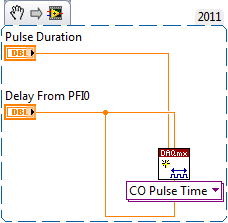
I couldn't open your VI as I use LV 2011 on this desktop computer.
However, you must just on delay initial as well as the low time some delay desired with respsect to PFI0 on the ctr0 task.
Other NI DAQ products behave differently, but the 6221 uses "shortly" for the initial delay for each output reset after the first.
Best regards
-
mark lines in different regions
I have an application that provides the two reports on the same page. I want to let the user decide several records in its first report and one record of another. Then, by clicking on the button SUBMIT, I want to catch the values selected in the two reports and make some PL/SQL on these data.
I tried to use tabular instead of reporting forms, to get info on selected lines of g_f function, but there is a restriction of the only form of tables per page.I'm afraid, but I think that this could not be possible with Wizard only. (for all I know)
Should be possible to aid in the form of 'manual', for example: the following code can delete the records selected in two different report region.
I try to 'translate' my code for the table 'emp' demo, hopefully rewrite well ;-)Report1:
Select
apex_item. CheckBox(11,empno) 'delete '.
EMPNO
ENAME
from emp where ENAME<>I2:
Select
apex_item. CheckBox(21,empno) 'delete '.
EMPNO
ENAME
from emp where ENAME > 'K '.In your process:
Start
because me in 1.apex_application.g_f11.count
loop
delete from emp where empno = apex_application.g_f11 (i);
end loop;
because me in 1.apex_application.g_f21.count
loop
delete from emp where empno = apex_application.g_f21 (i);
end loop;
end;I hope this might help.
Thank you
Stefano Corradi -
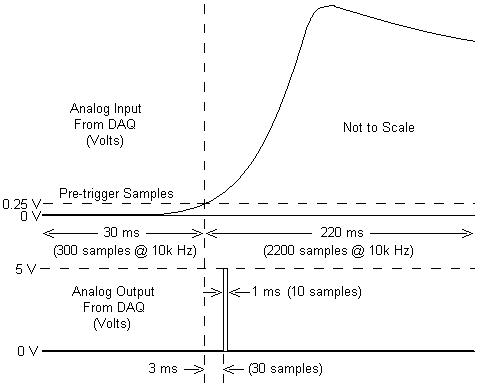
I am working with a combustion chamber and using a system of data acquisition (with the hardware OR SCB - 68) to read the pressure in the cylinder (such as analog voltage). I'm trying a pulse delayed, 1 millisecond to 5 volts of output once the pressure in the cylinder is high above 5 bar (which corresponds to an analogue voltage of 0.25 V). I would also like to record 30 ms samples before the trigger and 220 ms samples after the outbreak. The following image shows visually what I'm talking about.
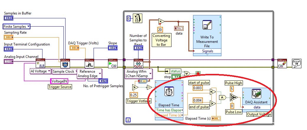
I created a LabVIEW VI (which is attached), but I keep running into 2 issues:
- When I run with samples finished after a period of time, I get error-200281which I don't quite understand.
- Using the Express VI 'Out of time' to keep time for the pulse I can not get a resolution of 1 millisecond, the pulse is not generated when I put the window between 0.003 and 0.004 seconds for high pulse (i.e. the resolution of 'Elapsed Time' seems to be too coarse).
I'm a beginner to LabVIEW sorry if my questions are trivial or my VI makes no sense, but I was stuck on this during more than a week. Any help would be greatly appreciated!
Thank you
Morgen
This isn't a good way to trigger a pulse.
Use a trigger DAQmx to send the pulse when your acquired signal exceeds 250 mV you specified.See this for DAQmx trigger:
-
I use a 6363. I want to trigger a pulse to synchronize incoming exactly N times. These impulses are coming in the ~ tens of kHz range.
My first idea was to make a task of CO County ticks on the same impulses and plug a relaxing break, but pause triggers apply only to the continuous acquisition.
My next idea was to hang the task of CO County ticks as the arm trigger defined on 'Good to go if it is high' and not 'arm on front amount', but it seems that it is not in the cards more.
Another idea was to use the impulses of synchronization entering as a sample of clock on a binary ripple of 10101010101 (N repetitions) and use the trigger set instead. But it seems that the binary signals cannot be deployed to advance until its next value on a rising or a falling edge, therefore leading to another each pulse.
Do I need to use a transistor outside Commission to do (with County CO ticks)? Who would do it, certainly, but it seems kludgy.
.... Are there clever ways to do? If not, is there a way to get the binary waveform to advance on the edges of increase or decrease?
It has a hardware signal as well (that confusingly enough is called the "change detection event"). "You can use it by setting your clock source' /
/ChangeDetectionEvent '. It will not be displayed in the drop down menu to DAQmx default termnals because it is considered 'Advanced' (see here). Best regards
-
How to create impulses cause a pulse width Variable AND at the same time
Hi all
I have a NI PCI-6251 that comes with 2 counters, a FREQOUT port and then some DIO, DAC and ADC. I want to trigger a pulse of variable width (easy to do with two counters) and a frequency closed, exit at the same time. So, I want to end up with a line that will display TOP for some variable time, while the other exits a train of pulses for a time variable. It is easy to do if you have 4 counters but I don't have one. Does anyone have an idea to implement these two things AND making them trigger at the same time with the PCI-6251 card?
The line is high for as long as your pulse train controlled?
If so, set up the first counter as output pulse, configure the 2nd as output continuous meter but with the internal of the first counter output as its trigger to pause (pause when it is low). Start the 2nd meter before the first.
If not, you will need to use the digital output to replace at least one of the counters (max sampling rate is 10 MHz, so this would give less resolution compared to the time base of 80 MHz counters). So you would simply write the waveform predetermined in the buffer and he clock at the desired rate and the number of samples to give the signal that you want. You need to generate some other subsystem as FreqOut clock.
Best regards
-
HP/Agilent 33120 A pulse, use burst mode
Hello
I'm trying to trigger a pulse of demand on from a HP 33120 A function generator.
The pulse must be a 0 - 5V simple, with frequency/period adjustable ramp. I was able to get as much of the FG by use of burst mode and trigger manually on the front panel. Now, I would like to get the same functionality from a LabVIEW VI.
Although there is a driver for the device, the burst feature is, unfortunately, not applicable to the model that I use. I found a similar problem on the forums and follow the code of the SCPI provided in the answer with some of my own humidification (http://forums.ni.com/t5/LabVIEW/33120A-Pulse-Mode/td-p/1088106).
Unfortunately, my VI does not produce the same waveform as the manual release out of the front panel. It hovers at the offset value and gives me a few square wave to zero when I run the VI. Square waves are spaced oddly and I usually see 4-5, even though I specified 1 cycle in VI. The 33120A reading, I feel that this is of my do not turn off the previous signal but, if this is the case, I can't understand how I would do.
I start to move away from using only the drivers by changing the code of the SCPI, but I'm still pretty new to this. Would appreciate some advice on what could be the problem. I modified my original VI twice; Once configure only the FG burst wave parameters manually and one just put up the waveform with no shine. The first don't not gave me much better results and the works of the latter very well so I'm back to the question of thinking are in transition.
I enclose the original VI (b) with the two modifications to the case where (c and d).
Hope to hear from you,
Yusif Nurizade
Edit: Burst chain should say TRIG: SOUR BUS instead of EXT, although neither works.
Or you have the appropriate firmware in you function generator?
Have you checked this with Agilent? -
Acquire analog data entry triggered by the great time and low time of a pulse meter
Hi all
I'm writing a VI in labview 8.1 version to test the sensors. The power supply of the sensor is pulsed and I need to get a value when turned on the power of the sensor and the power of the sensor is turned OFF (measure Max voltage when the current flows through the circuit and voltage min when no current flows through). My cycle is like ON 2 seconds for 8 seconds.
And I want to acquire a reading in each of those States permanently. I am able to use a pulse meter to make the pulse but how can I tie this with the recording of data, then you can be sure that I log into a data point in the State ONE and the other to the OFF state?
Thank you
SJ
Acquire the pulses of the meter on a different path to analog input. When it is high your sensor is activated.
Lynn
-
How to generate a variable frequency pulse train constantly
Hi all
I am using NOR-USB-6259 (BNC) to send signals of impulse to the position of a servo with labview motor control. The position of the servo-motor control follows these rules:
- The pulse train number determines how many degrees the motor;(par exemple la position angulaire dele de moteur)
- The pulse frequency determines how fast the engine is running; (for example the engine rotation speed)
- Digital determines the direction of rotation of the engine (for example in the clockwise or counterclockwise)
My question is when I have to continuously generate a body finished, train signal in a period of time. Here's a sample:
Time (s)
Number of pulses
Direction of rotation
(1 clockwise, counterclockwise 0)
Frequency
0-1
923
1
923hz
1-2
3540
0
3540hz
2-3
1751
1
1751hz
3-4
2663
0
2663hz
4-5
353
0
353hz
5-6
1017
1
1017hz
6-7
3436
1
3436hz
7-8
10 p
0
302hz
8-9
1513
1
1513hz
9-10
570
1
570hz
Here is the explanation of this table, the motor continues to turn clockwise for 0 ~ 1s. When the time reaches 1 s, the engine simply fill out the rotation of 923 pulse signals. And then the engine starts to turn clockwise for 1 sec ~ 2 s. When the time reaches 2 s, the engine simply fill out the rotation of 3540 pulse signals. So we can see that the speed of rotation of the motor to 0 ~ 1 s is different from the speed in 1 ~ 2 s. Namely, the frequency of the signal from pulse to 0 ~ 1 s is different from the frequency in 1 ~ 2 s.
I already use the DAQmx counter output, it can simply generate pulse signal with some numbers and some frequency only once. The attachment is the vi that allows to generate a digital pulse train finished the meter output channel and frequency, cyclical, delay report Initial and idle state are all configurable.
How can I continuously generate a series of pulse train with a variable number and frequency for a certain period of time.
Thank you very much for your help!
The frequency 'on the fly' control requires intervention of software and can not guarantee a specific number of impulses for each rate (which I assume you want because it's an engine step by step).
If it was me I would do one of them instead:
1. use the digital output for everything. The digital output at a higher clock rate and build the waveform to give you the desired number of steps and management. This method would give less temporal resolution than others.
2. use a task of meter output, 1 section at a time. Reconfigure and restart the task for each section after the management output setting. This method could introduce a delay between each section.
3. purchase of new equipment - X series supports put buffered outputs of meter that can do what you ask.
Best regards
-
How to hide the trigger on the top layer
Hello
can someone help me with this problem?
Each icon is a trigger in the other layer.
When I clicked on the icon, it will display the target (white box), but somehow the other icon is always on display.
I tried to move the layer to the trigger, but it cannot be moved anywhere on the layer.
I thought to create another separate page for each icon, but it will not reach the design I wanted.
Can someone help me how to get the icon disappear please?
IM using muse CC 2015.2 Release
Thank you
Raydi

Check the options in the widget settings. If it is enabled, clear the triggers on the top .

David
-
Back to the indicator of speed and hash/tick marks
so... I am back! and here's my problem:
I went during the preliminary discussions, because I simply can't understand why this particular counter hatch not line up correctly. Here's what I do: (brands of hash on the speedometer equals 11 and there is a gap of 90 degrees at the bottom of the speed indicator, there are 21 small hatch).
I create the outer circle and then the circle (the inner circle is not actually necessary for the moment).
on a new layer, I create the great hash mark;
I select the outer circle and the brand of hash and copy them to another layer
I turn them: 360-90/11 = 24.55 with 10 copies (see circle top of page)
Then I copy the original outer circle and the original big hash mark into a new layer and adjust the weight of the race to represent the small hash mark
then I turn 21-90/360 = 12.86 with 20 copies (see middle circle)
and you can see my background circle that both sets of hatching don't align properly. What I am doing wrong?

Thank you
Jber
Jber,
You must use (360-90) / 10-(360-90) / 20, because one is considered as the number 0, and there are 10/20 intervals, i.e. 270/10 = 27 and 270/20 = 13.5 so two small correspond to a big (intervals). The gap is also much more than 90 degrees (about 114.5 degrees).
The reason the strange(ness of the) misalignment is the division by 21 (20 + 1) is only half as well off is the division by 11 (10 + 1).
You have to rotate so that the gap of 90 degrees down of course.
-
Error no valid identifier when you try to create a trigger
Hi all
I get this weird error when you try to create a trigger. Basically, it updates a table of different relationship on INSERT or UPDATE.
The error I get is:
* PL/SQL: ORA-00904: "cid": invalid identifier *.
The column exists and matches the data type (number). Any help appreciated. bit at loss where I'm wrong.SET SERVEROUTPUT ON CREATE or REPLACE TRIGGER UPDATE_REL_TABLE AFTER INSERT OR UPDATE ON XF_PROJECT_CODE FOR EACH ROW DECLARE customer_count NUMBER; n_cid NUMBER; BEGIN -- CHECK if company exist SELECT COUNT(*) INTO customer_count FROM XF_CLIENTS WHERE UPPER(client_name) = UPPER(:NEW.company); CASE WHEN customer_count > 0 THEN -- GET CUSTOMER ID select t.cid INTO n_cid FROM XF_CLIENTS t WHERE t.CLIENT_NAME = :NEW.company; // ERROR HERE!! -- UPDATE relationship table INSERT INTO XF_CLIENT_CODE_R (PROJECT_CODE_ID, cid) VALUES (:NEW.project_code_id, n_cid); ELSE -- customer does not exist n_cid := XF_CLIENTS_SEQ.NEXTVAL; -- Create client INSERT INTO XF_CLIENTS(cid, client_name) VALUES(n_cid, :NEW.company); -- update relationship table INSERT INTO XF_CLIENT_CODE_R(project_code_id, XF_cid) VALUES (:NEW.project_code_id, n_cid); END CASE; END; / SHOW ERRORS;Good fishing! Who'd do all right.
-
Can I have a button stuck in MSO trigger a different MSO?
I have a button stuck in an MSO, how can I have it trigger a function "go State" of a completely different MSO?
Currently, it only allows me to select the current DSO it is stuck in.Any help would be great!
Thank you!
You cannot jump to a MSO with a button that is part of a different MSO. This is a limitation of InDesign.
-
Call a package in another schema of a trigger?
Is there a method to call a procedure of a trigger package when the package is in a different schema than the trigger (table)?
Do you need a dblink to run a procedure in a different diagram in the same database?The current scheme should have a privilege on the package execute
example of
HR schema has a package pkg_emp
from HR Schema  -> Grant execute on pkg_emp to SCOTT

Now the table is in SCOTT schema
and the table in this schema can all the
package using HR.pkg_emp.
Do you need a dblink to run a procedure in a different diagram in the same database?
>No, you need not create the database link
Sanjay
-
How to change DI unbuffered mode
My request is when a fall from digital input (camera ready) edge arrives, it will trigger a pulse counter 0, open the shutter of camer.
The following code does this:
camShutterOutputTask.COChannels.CreatePulseChannelTime ("Dev1/ctr0", "",)
COPulseTimeUnits.Seconds, COPulseIdleState.Low,
0,
0.000001,
(((double) exposure_time) / 1e6);camShutterOutputTask.Triggers.StartTrigger.ConfigureDigitalEdgeTrigger ("/ PFI0/Dev1", DigitalEdgeStartTriggerEdge.Falling);
camShutterOutputTask.Triggers.StartTrigger.Retriggerable = true;On my PCIe-6323, PFI0 is by default configured with P1.0, so I connected physically ready to P1.0 camera entry.
I just want to trigger the camera several times. After the required number of triggers, I'll just ignore all the following input signals. The following code configures the input channel to do so:
camReadyInputTask.DIChannels.CreateChannel ("Dev1/port1/$line0", "", ChannelLineGrouping.OneChannelForEachLine);
() camReadyInputTask.Timing.ConfigureChangeDetection

                   "",

                   "Dev1/port1/$line0,"

                   (SampleQuantityMode.FiniteSamples, num_of_frames);
The problem is when I run the program, I get the error: "some lines do not support buffering operations. Ensure that lines are supported buffering operations are used in the task. If you use the calendar to change detection, the task should be replaced by without buffer to support these lines. »
If I use port 0 in the code instead of port 1, he makes the mistake, and it limits the number of input signals just like what I need. However, port 0 is not connecting to any PFI, so I can't use it in the trigger to start for the shutter of the camera.
Does anyone know how is:
1. change a task in unbuffered mode or
2 re - router port 0 to a PFI?
Thanks for the reply Ashly. I'm new to DAQmx and there is still a lot to learn.
The loop thing involves waiting timed software and concerns me.
I have found a workaround that calls a callback function whenever the meter changes its output:
camShutterOutputTask.SynchronizeCallbacks = true;
camShutterOutputTask.CounterOutput += new CounterOutputEventHandler (camShutter_callback);...
' Private Sub camShutter_callback (object sender, CounterOutputEventArgs e)
{
trigger_count ++;
Console.WriteLine ("trigger count =" + trigger_count. (ToString());
If (trigger_count > = num_of_frames * 2)
{
Try
{
camShutterOutputTask.Stop ();
camShutterOutputTask.Dispose ();...
startCaptureButton.Enabled = true;
}
catch (System.Exception Exception)
{
MessageBox.Show (exception. (Message);
}
}
}In camShutter_callback(), I continue to follow a global counter and if it is greater than num_of_frames * 2 (since the callback will be triggered by rising and falling pulse edge), I stop all tasks.


Maybe you are looking for
-
Unable to update the Code of error - Windows Vista Service Pack 1 (KB936330) -: 80070017
original title: could not update - Windows Vista Service Pack 1 (KB936330) Impossible to update - Windows Vista Service Pack 1 (KB936330) Installation status: failure. Error details: Code 80070017
-
Windows 7 hangs after successful Remote Desktop Session
I have a dual boot Media-PC with XP Pro and Windows 7 Ultimate edition. This PC is part of my stereo and not convenient to do lot of keyboard work, as optimizing the WMP music library. Thus, historically I use XP Pro using remote desktop sharing. Thi
-
InDesign CS6 reinstall with beta key
HelloI have a computer with InDesign CS6 installed and I will be performing a clean install of Windows 10. I used a key Locator to find the key and spoke with a conversation agent who told me it was a beta key.My questions are:(1) where to find the I
-
Outer Join and joining several Tables
Hello Oracle Database 10 g Express Edition Release 10.2.0.1.0 - product I have three tables AddProject, AssociateProjectLead, AddAssociate. Now I'm generating a report who will join AddProject and AssociateProjectLead for a list of all the projects,
-
Impossible to connect to the physical console under ESX4
I have physical access to that server, try to connect to this server with the credentials of the root, and once I enter 'root' and wait for password prompt, I get nothing. The blionks of slider under it and I'm stuck. I pressed AltF11 to return to th