Generate a pulse trains finished redeclenchables 2 of different duration using 2 counters
Hello
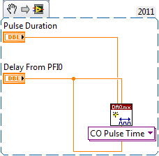
What I want to do is to generate at the same time 2 redeclenchables finite pulse trains using my PCI-6221.
To be more clear, take a look at the attachment.
Relaxation is in/dev/PFI0 for example and I want 2 impulses/dev/ctr0 and/dev/ctr1 at the same time.
I can easily produce/dev/ctr0 or/dev/ctr1, but never/dev/ctr0 and/dev/ctr1 at the same time.
It sounds feasible that I want to achieve?
Thank you very much.
Adrian
I couldn't open your VI as I use LV 2011 on this desktop computer.
However, you must just on delay initial as well as the low time some delay desired with respsect to PFI0 on the ctr0 task.
Other NI DAQ products behave differently, but the 6221 uses "shortly" for the initial delay for each output reset after the first.
Best regards
Tags: NI Hardware
Similar Questions
-
How do you create a pulse train finished using a FP-CTR-502?
Recently, I replaced my FP-PG-522 module with a module FP-CTR-502, to achieve higher output frequencies (FP-PG-522 freq to maximum output is 5 kHz, while the FP-CTR-502 output max freq is 16 kHz).
I need to be able to generate a pulse train finished. Has anyone created a pulse train finished using a FP-CTR-502 module front? I started to study the issue, but my ideas so far have been complicated (compared to doing it in a PG module).
Advice on this would be much appreciated.
I can answer this question myself!
The answer is in the * OLD * version (July 2000) the operator of the manual for the FP-CTR-502. For some reason, it has been removed from the version the most recent (June 2003).
See page 11 of this link for more information:
http://www.NI.com/PDF/manuals/322660a.PDF -
Generate a pulse train, NI 9402 modules in cDAQ-9174 chassis
I have two modules NI 9402 in a cDAQ-9174 chassis.
When I output a pulse train on a specific line of the PFI to a specific module, the pulse train is out on the right line of PFI, but on BOTH modules.
I want that the pulse train out only one of the modules.
for example, I select cDAQ2Mod1/ctr1 to output a pulse train on PFI3 of module one. I hear the pulse module one PFI3 train, but I also get it on PFI3 of module 2.
I am also a measurement of separation of two edges with a different counter, but I don't seem to have this problem. (The measure only works when I have the signals connected to the module that I've specified.)
-Paul
This is the Vi I work with.

Hmmm... Looks like it's actually only after I exit a signal on that line. Maybe I should try to clear the line.
-Paul
-
How to generate a variable frequency pulse train constantly
Hi all
I am using NOR-USB-6259 (BNC) to send signals of impulse to the position of a servo with labview motor control. The position of the servo-motor control follows these rules:
- The pulse train number determines how many degrees the motor;(par exemple la position angulaire dele de moteur)
- The pulse frequency determines how fast the engine is running; (for example the engine rotation speed)
- Digital determines the direction of rotation of the engine (for example in the clockwise or counterclockwise)
My question is when I have to continuously generate a body finished, train signal in a period of time. Here's a sample:
Time (s)
Number of pulses
Direction of rotation
(1 clockwise, counterclockwise 0)
Frequency
0-1
923
1
923hz
1-2
3540
0
3540hz
2-3
1751
1
1751hz
3-4
2663
0
2663hz
4-5
353
0
353hz
5-6
1017
1
1017hz
6-7
3436
1
3436hz
7-8
10 p
0
302hz
8-9
1513
1
1513hz
9-10
570
1
570hz
Here is the explanation of this table, the motor continues to turn clockwise for 0 ~ 1s. When the time reaches 1 s, the engine simply fill out the rotation of 923 pulse signals. And then the engine starts to turn clockwise for 1 sec ~ 2 s. When the time reaches 2 s, the engine simply fill out the rotation of 3540 pulse signals. So we can see that the speed of rotation of the motor to 0 ~ 1 s is different from the speed in 1 ~ 2 s. Namely, the frequency of the signal from pulse to 0 ~ 1 s is different from the frequency in 1 ~ 2 s.
I already use the DAQmx counter output, it can simply generate pulse signal with some numbers and some frequency only once. The attachment is the vi that allows to generate a digital pulse train finished the meter output channel and frequency, cyclical, delay report Initial and idle state are all configurable.
How can I continuously generate a series of pulse train with a variable number and frequency for a certain period of time.
Thank you very much for your help!
The frequency 'on the fly' control requires intervention of software and can not guarantee a specific number of impulses for each rate (which I assume you want because it's an engine step by step).
If it was me I would do one of them instead:
1. use the digital output for everything. The digital output at a higher clock rate and build the waveform to give you the desired number of steps and management. This method would give less temporal resolution than others.
2. use a task of meter output, 1 section at a time. Reconfigure and restart the task for each section after the management output setting. This method could introduce a delay between each section.
3. purchase of new equipment - X series supports put buffered outputs of meter that can do what you ask.
Best regards
-
Problem with the generation of two internal counters pulse trains
Hello
I do a control of temperature for two heaters, OR 9472 (output module digital), NI 9271 (RTD for measuring temperatures) and cDAQ-9174 chassis. So, I use the internal meter NI 9174 to generate two pulse train on the outputs (I tried with both cases-> pulse continuous and finite). Before that, I have two separate PID.vi, in which each sent the percentage of cycle of obligation for the two tasks of pulse generation (I configured these tasks with the physical channel cDAQ1Mod1/ctr0 and cDAQ1Mod1/ctr1). The problem is when I run the program, because the application initially worked fine, but after a few seconds the communication between the chassis and the application is not respected (no error message, but the external LEDs on the NI 9472 module had been disabled and stopped too NI 9271 module temperature readings). Then I tried to stop it with a 'Stop' button, but nothing happens. After, I abandoned the race and still nothing happened. So, I finished the Labview program with the Task Manager and a message appeared "reset VI: xxxxx". Finally, I have to restart my computer to run the program again. Can anyone help with this please? If you need more information, let me know.
Kind regards
Hi Luis,.
I have the error cluster connected. But I solved my problem in a different way. I don't know why, but when I configured my RTD module with the DAQ assistant to test some of my design in a new file in VI, the RTD module works fine, but if I copy the entire program logic (include my DAQ assistant) back to my main VI folder and run the application, only for communication between my DAQ hardware and my software works there shortly. So I solved my problem set up any device or module in the same file from the application again and problem disappears.
Thanks for your help.
Luis C.
-
Counter/Timer Pulse Train generation
Hello
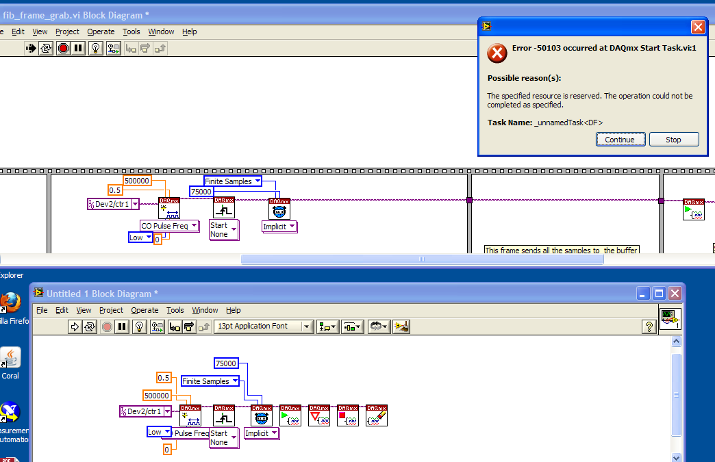
I'm having some difficulty to understand why a particular VI I does not work (upper part of the image below), I was wondering if someone could give me an idea of the cause of the error message. I have a counter/timer, which I use to generate a pulse train. It works very well on samples of "continuous", but when I turn it on to 'finished samples' I get an error of "resource is reserved" when it comes to the DAQmx VI of 'play '.
I made an another VI (lower part of the image) and it works very well with finished samples. So basically I wonder what's different on finishes versus continuous sampling which could cause a resource to book or not. (the Board of Directors is a PXI-6281 if it matters)
Thank you
Adam
OK, I just looked through the manual and it seems that when you do a finish on a counter pulse train generation, the jury must in fact to divert the OTHER counter.
This may have been aparent earlier if the error message about what resources he tried to get was more prolific.
In any case, problem solved I guess.
-
How can I specify a delay generates a pulse meter?
Hi all
I have a question on the use of the meter to generate the pulse train. I did not how to program but I try the test panel in MAX and I see that it generates pulse train to certain rates and with a pulse duration. I think if it is possible to generate only a single pulse with given the duration of the impulse to sometimes after I start the job? I have a code to generate an analogue waveform, waveform of 35ms. I wonder if it is possible to synchronize the output of the analog waveform and counter such to 12.5ms after that the output waveform has started, I send this unique pulse from the meter port on. I have no idea how to do that, I think to use a delay but it is difficult to accurately control the time exactly 12.5ms.
Well, assuming DAQmx_Val_Low for the resting State, fires the meter will wait the initial delay and then generate a pulse at the time you request. Little time is not actually used in this example simple impulse.
From what you described, you must add a trigger to start your task of meter output (DAQmxCfgDigEdgeStartTrig) to you can set the meter to trigger off the beginning of analog output trigger. Set the initial delay on the counter for 12.5 ms. Start the task of counter in front of the task of the analog output. You should get your pulse 12.5 ms after you have started the task of the AO.
Best regards
-
Continued use of digital dashboard to stop a generation pulse train
Hello
I need to generate a train of pulses for a period of time. However, this period is variable, and because of that I can't
Use the finite number of samples.
The pulse train must be output depending on the State of the digital I/o. When the line output goes high, must be output of the pulse train.
and when he goes down the pulse train should be stopped.
I use a USB-6212, but is already using one of the available counters for the measurement of pulse width. I tried to do a
AND logic with the pulse train and line activate, but due to the execution time of vi this solution modifies the pulse train
frequency, which is not acceptable.
Thanks in advance,
Mariana.
Hi Marianne,.
Your previous message mentioned "line in/out" (in the singular) and "enable line" (in the singular), isn't "the i/o lines" (in the plural). Are the two edges on the same line in/out? Or are they on separate i/o lines (for example, climbing on PFI0, falling on PFI1)? Can you clarify your needs?
If the fronts and sides come from the same line of output, then a relaxing break seems to do what you want: cause the meter generate impulses while the input/output line is high and cause the meter to stop while the input/output line is low. However, if you start the job, while the input/output line is high, it will immediately start out impulses. If you want to wait the first front line input/output to generate impulses, you can use a trigger 'start of arms' (which is just below "break" in the node property). When the trigger 'arms beginning' arrives, the meter will be armed, and therefore, the task uses the break to determine when to generate impulses. Using pause and start the same counter task returns error-200146, "put in Pause and start triggers cannot be active in this task," but using break and triggers 'arms beginning' in the same task of counter should be correct.
If you want to increase the edges of PFI0 to start the meter and the fall of the edges of PFI1 to stop the meter, which is more complicated and it will take thought additional (and possibly additional hardware).
Brad
-
Create two independent signals and a pulse train with NI USB-6259
Hi all
I'm new to the forum, I searched but I've found no info about it.
I have recently set up a vi that is able to generate from an NI USB-6259 case two different signals in frequency, amplitude and phase (see attachment).
To do this with each cycle of the memory buffer size is changed accordingly for frequencies in order to see a whole number of periods and, thus, having not leak in the generation (or breaks).
Now, I would like to generate a pulse train at a frequency that is an integer multiple of the frequency of the input signal (not the 50 Hz one).
The resulting frequency of the pulse train could be changed on the fly (or at least be updated at each new round of vi).
I'm stuck because I have already said that two analog output channels and I want the pulse train so that a digital camera for my Board (channel PFI) output, you have any ideas?
Thank you very much
Alberto
PS. the vi is "program generazione.vi" but you must first install "signal.vi production".
Hello
It is a simple .vi which generates a configurable, buffered pulse train dynamically. I also want to let you know that with this type of advice (DAQ), it is impossible to update the output in real time. You must be careful because the time between you use "DAQmx Write" and the output effective physical change not IS NOT FIXED.Kind regards
Matteo
-
Two pulse trains with delay of fixed phase using USB-6216
I need to generate two pulse trains of continuous with the 2nd train of pulses at a set for the first time. Is this possible with the USB-6216?
Yes it can.
You will need to set up a dummy analog input task and set the two tasks of counter to serve their trigger start of AI/StartTrigger. Your first meter will start immediately, but your second task is to counter, specify a value for the terminal 'initial period' of the DAQmx VI create channel.
This 'initial period' will be in a few seconds and the period after receiving the start trigger that starts the second pulse train.
-
External trigger a continuous pulse train
Hi-
How outside wearing a keep to my USB-6343 pulse train?
Specifically, I want to use a digital input signal as the gateway for the pulse train.
I use LV 2010.
Best
Dar Bahatt
Dar Hi,.
I would like to revisit my advice earlier given new items. You always want to use 2 counters for the pulse train:
1. use a configured counter for continuous output with a relaxing break.
2. use the other counter to generate a pulse very long, triggered on the front of your switch to home. You must use this as the break to relax instead of the switch House directly.
You can query the status of the release of the 2nd meter so that you know in the software when the switch of the House was saved. At this point, you stop the two tasks of meter in the software (first stop a continuous). You can write a logic 0 to PFI lines after that stains from countertop were arrested for set State to 0 before the next execution - since you are behind the wheel of a stepper motor, I do not think that the width of the pulse of the last matter much, as long as the counter is reset.
Best regards
-
How can I use two counters to capture a pulse ttl for a specified time
Configuration: Card counting 6062 PCI w / BNC 2121 Board running under LV 9.0 PerkinElmer Avanlance Photodiode (SPCM-AQRH-13)
I searched through the forums and fell on the theme of framing an image while collecting signals from a source for a specified time.
The example in terms of falkpl in 2005:
"
Dismal Hello,
I'll try to point you in the right
direction to start coding the application, but do not forget my
suggestions have to be modified to your specific request.For
the task output redeclenchables finished meter you need to
your counter seconds in this application, I suggest to take a look
in the Finder example in LabVIEW ('Help' are examples) and less
DAQmx hardware entry & exit"" generating digital impulses. Here,
you will find some Gen dig Pulse - Retriggerable.vi. You can use this for
Create your door 4 pulses ms it's over (not a pulse train) and
redeclenchables (for each time you go to the next step.In
regards to the configuration of the first counter, there are several things to
consider, and I can offer initial help to get set up. You
in-house allows to route internal CTR1 (4ms of pulse) output for your CTR0
Door to measure only during the time. Here are additional
Info to do this in LabVIEW. The source of your task of edges ABOVE County
will be the TTL signal you are measuring and counting. It comes
on the PFI line that corresponds with CTR0 Source.When
you make a measurement finished with CTR0, you will take only heads while
the door is high and your source has a rising edge. You can set the
measure over to start on a trigger, which is not clear in this
for example, that you have identified. Since you know that you have a finished 4ms pulse
time to measure, you can set the duration of your measure
as a result.I found this
Forum which may help some, but the coding is
textual. I hope this can give you a good starting point for
programming. -
Salvation;
Here is the solution for your problem.
The cause is that "Gen dig Pulse Train-Finite" uses Ctr0 both Ctr1.
Please refer to:
"When you do a finite pulse train generation, a counter generates pulse train, and the other counter generates an impulse that acts as a barrier to the first counter. If you change the pulse train to generate continuously or
only generate a pulse, you can run two tasks of meter at the same time without error. »
http://digital.NI.com/public.nsf/allkb/04BEDD9E9E91ED3486256D180048116D
I used Ctr0 and Ctr2, jumping Ctr1 as it is reserved by "" Gen dig Pulse Train-Finite ". I works very well.
Kizito.
-
FPGA to generate the counter and pulse train
Hello
I have some experience with Quartus, but new on the FPGA OR.
I have a PCI-7811R. I'm trying to use it to illuminate sequentially 144 LEDs repeatedly. The duration of each pulse is 480us.
Basically, I need to generate a pulse and generator of a counter to record the number of pulses and, according to this number, select which light is lit.
I designed a pulse generator train based on an example of using FPGAS and added a counter in it. You can see in the attached vi.
My question is,
When I put the I/O node inside loops call single cycle, it can generate the correct pulse. However, when I tried to use the local variable to transfer data from the SCTL and then plug it on another node of I/O, I can't detect the pulse signal when I measured this I/O.
Is there something wrong with my code when I try to transfer the data of the SCTL? Can I also use local variable to transfer the value of counter, because I will need it in the next part.
Thank you!
If you are referring to the wired local variable to DIO2 in your attached VI, the problem is very simple: it is outside a loop, then it executes only once. Put this local variable and the node of IO in a loop and I think you'll get something close to the impulse you expect (although if it is not in a loop of single cycle you will have exactly the same calendar).
-
How to connect to the list of the pins for a redeclenchables pulse train
Hello
I'm relatively new toDAQmx, especially for the counters. I have problems to determine what pins to plug on the DAQ card. I would like to run the vi described here, but am not sure how to connect the card. I looked at the manual of the X series for the pinout descriptions, but I don't know how they apply to the program on this page. When I connect DOOR a meter, THE, A, B pins, etc.?
Any input on what to connect or pages that may make how to connect the counters would be very useful.
Thank you.
Your most recent post of links to an example more advanced sounding & I recommend that stick you with something simple to start.
Your first post links to such an an example where the signal of pulse train going out of Ctr0_Out. Ctr1 is used to make the trigger and the 'break' (enable / disable) Ctr0. However, much of this stuff is configured using some features of DAQmx such that you don't need to physically connect the pins between the two counters.
Only physical wiring that you need is to plug your physical digital trigger to the PFI1 signal and connect Ctr0_Out to some external thing must receive them. As long as your device is called "Dev1", I think this example to work.
I know there are some docs useful for more general info on the pins meter & behavior, but I don't remember quite so that I have not watched for them for many years. Meanwhile, here is a * little * bit General description I wrote myself once.
-Kevin P
Maybe you are looking for
-
Options configuration NOR in MatLab compiler
Hello I am compiling a .mdl in a .dll file. I followed the instructions OR on the way to link this (http://www.ni.com/white-paper/13066/en) and it works fine. I'm curious to know what options exist under "Code Generation-> NI Configuration-> addition
-
A way to remove the following pre-installed applications? * Facebook (given the permissions of this app, I find obscene that she cannot be removed)* 4 x Xperia social engine apps* Unlimited music* Unlimited Video* Socialife* Social life* SocialEngine
-
performance com_sync_index problem
How I can dissect from performance in ctxsys.drvdml.com_sync_index (: idxname,: idxmem,: partname); is run?
-
I just downloaded after affects CC and its been stuck on finishing now for about 4 hours. Is there a work around or how should I do to fix this?Thank you!
-
Need help on how to increase the seriousness on the issue in my oracle support
HelloPlease, help me make the problem worse in my oracle support.Thank youPrashant Joshi