How to generate a variable frequency pulse train constantly
Hi all
I am using NOR-USB-6259 (BNC) to send signals of impulse to the position of a servo with labview motor control. The position of the servo-motor control follows these rules:
- The pulse train number determines how many degrees the motor;(par exemple la position angulaire dele de moteur)
- The pulse frequency determines how fast the engine is running; (for example the engine rotation speed)
- Digital determines the direction of rotation of the engine (for example in the clockwise or counterclockwise)
My question is when I have to continuously generate a body finished, train signal in a period of time. Here's a sample:
|
Time (s) |
Number of pulses |
Direction of rotation (1 clockwise, counterclockwise 0) |
Frequency |
|
0-1 |
923 |
1 |
923hz |
|
1-2 |
3540 |
0 |
3540hz |
|
2-3 |
1751 |
1 |
1751hz |
|
3-4 |
2663 |
0 |
2663hz |
|
4-5 |
353 |
0 |
353hz |
|
5-6 |
1017 |
1 |
1017hz |
|
6-7 |
3436 |
1 |
3436hz |
|
7-8 |
10 p |
0 |
302hz |
|
8-9 |
1513 |
1 |
1513hz |
|
9-10 |
570 |
1 |
570hz |
Here is the explanation of this table, the motor continues to turn clockwise for 0 ~ 1s. When the time reaches 1 s, the engine simply fill out the rotation of 923 pulse signals. And then the engine starts to turn clockwise for 1 sec ~ 2 s. When the time reaches 2 s, the engine simply fill out the rotation of 3540 pulse signals. So we can see that the speed of rotation of the motor to 0 ~ 1 s is different from the speed in 1 ~ 2 s. Namely, the frequency of the signal from pulse to 0 ~ 1 s is different from the frequency in 1 ~ 2 s.
I already use the DAQmx counter output, it can simply generate pulse signal with some numbers and some frequency only once. The attachment is the vi that allows to generate a digital pulse train finished the meter output channel and frequency, cyclical, delay report Initial and idle state are all configurable.
How can I continuously generate a series of pulse train with a variable number and frequency for a certain period of time.
Thank you very much for your help!
The frequency 'on the fly' control requires intervention of software and can not guarantee a specific number of impulses for each rate (which I assume you want because it's an engine step by step).
If it was me I would do one of them instead:
1. use the digital output for everything. The digital output at a higher clock rate and build the waveform to give you the desired number of steps and management. This method would give less temporal resolution than others.
2. use a task of meter output, 1 section at a time. Reconfigure and restart the task for each section after the management output setting. This method could introduce a delay between each section.
3. purchase of new equipment - X series supports put buffered outputs of meter that can do what you ask.
Best regards
Tags: NI Software
Similar Questions
-
FPGA to generate the counter and pulse train
Hello
I have some experience with Quartus, but new on the FPGA OR.
I have a PCI-7811R. I'm trying to use it to illuminate sequentially 144 LEDs repeatedly. The duration of each pulse is 480us.
Basically, I need to generate a pulse and generator of a counter to record the number of pulses and, according to this number, select which light is lit.
I designed a pulse generator train based on an example of using FPGAS and added a counter in it. You can see in the attached vi.
My question is,
When I put the I/O node inside loops call single cycle, it can generate the correct pulse. However, when I tried to use the local variable to transfer data from the SCTL and then plug it on another node of I/O, I can't detect the pulse signal when I measured this I/O.
Is there something wrong with my code when I try to transfer the data of the SCTL? Can I also use local variable to transfer the value of counter, because I will need it in the next part.
Thank you!
If you are referring to the wired local variable to DIO2 in your attached VI, the problem is very simple: it is outside a loop, then it executes only once. Put this local variable and the node of IO in a loop and I think you'll get something close to the impulse you expect (although if it is not in a loop of single cycle you will have exactly the same calendar).
-
Create two independent signals and a pulse train with NI USB-6259
Hi all
I'm new to the forum, I searched but I've found no info about it.
I have recently set up a vi that is able to generate from an NI USB-6259 case two different signals in frequency, amplitude and phase (see attachment).
To do this with each cycle of the memory buffer size is changed accordingly for frequencies in order to see a whole number of periods and, thus, having not leak in the generation (or breaks).
Now, I would like to generate a pulse train at a frequency that is an integer multiple of the frequency of the input signal (not the 50 Hz one).
The resulting frequency of the pulse train could be changed on the fly (or at least be updated at each new round of vi).
I'm stuck because I have already said that two analog output channels and I want the pulse train so that a digital camera for my Board (channel PFI) output, you have any ideas?
Thank you very much
Alberto
PS. the vi is "program generazione.vi" but you must first install "signal.vi production".
Hello
It is a simple .vi which generates a configurable, buffered pulse train dynamically. I also want to let you know that with this type of advice (DAQ), it is impossible to update the output in real time. You must be careful because the time between you use "DAQmx Write" and the output effective physical change not IS NOT FIXED.Kind regards
Matteo
-
How to use NI9474 and cdaq9172 to generate the right variable cycle pulse 1 kHz
Hello, I would like to use a NI9474 (in a cdaq9172 chassis) to send a square with a frequency of 1 kHz wave. The cycle will change just about every second (based on NI9205 voltage readings in all separate loop, by controlling the local variable 'duty'). It is important to have a temporal resolution of decent output; that is the difference between 50% and 51% of duty cycle must be determined. 9474 says that it has a speed of 1, so I expect that this is possible. This is used for a buck converter. The output is switching on and off a MOSFET, which only needs 5 volts, and less than a mA, when on. I tried a "simulate" with a square wave signal using a frequency of 1 kHz and 100kS/s and introduced in a DAQ assist with dynamic data to the converter Boolean between (probably not the best approach I admit). I tried also implemented using the DAQmx screw (without help). In both cases, I got an error that says that I need an external clock. I know that the chassis has an internal counter. This could be used for synchronization? I looked at examples of Pulse counter, but which seems to be to use a meter as output, not a digital channel, so I'm a little confused. The numeric examples do not seem to be what I want either. If I can't use the chassis for synchronization, it is possible, that I could get a NI9401. Could I use this counting or establishment of a clock (I could attach a function generator using a square wave of 1 Mhz for example)? For example with a 1 Mhz clock, then for a 50% duty cycle signal 1 kHz, after 500 clocks range from low to high and high to low after the other 500, (or 510 and 490 in 51% duty). Is something like that possible? Thanks for any advice, Thomas I should confess do not understand the things of meter too well at this point. Many of the examples I've seen, are apparently complicated screws.
Hi Thomas,
You can certainly do with a counter pulse train generation by using your 9474 in a cDAQ-9172 chassis. Make sure that the module is in the slot 5 or 6 (latest chassis do not have this restriction). Examples of pulse train located in the finder example under entry and exit-> DAQmx hardware-> generating digital impulses. The example of Gen dig Pulse Train - Continuous.vi is probably in the neighborhood of what you want.
To update the market on the fly factor, write the Co.Pulse.DutyCyc channel property after the task starts.
-
How to create impulses cause a pulse width Variable AND at the same time
Hi all
I have a NI PCI-6251 that comes with 2 counters, a FREQOUT port and then some DIO, DAC and ADC. I want to trigger a pulse of variable width (easy to do with two counters) and a frequency closed, exit at the same time. So, I want to end up with a line that will display TOP for some variable time, while the other exits a train of pulses for a time variable. It is easy to do if you have 4 counters but I don't have one. Does anyone have an idea to implement these two things AND making them trigger at the same time with the PCI-6251 card?
The line is high for as long as your pulse train controlled?
If so, set up the first counter as output pulse, configure the 2nd as output continuous meter but with the internal of the first counter output as its trigger to pause (pause when it is low). Start the 2nd meter before the first.
If not, you will need to use the digital output to replace at least one of the counters (max sampling rate is 10 MHz, so this would give less resolution compared to the time base of 80 MHz counters). So you would simply write the waveform predetermined in the buffer and he clock at the desired rate and the number of samples to give the signal that you want. You need to generate some other subsystem as FreqOut clock.
Best regards
-
How do you create a pulse train finished using a FP-CTR-502?
Recently, I replaced my FP-PG-522 module with a module FP-CTR-502, to achieve higher output frequencies (FP-PG-522 freq to maximum output is 5 kHz, while the FP-CTR-502 output max freq is 16 kHz).
I need to be able to generate a pulse train finished. Has anyone created a pulse train finished using a FP-CTR-502 module front? I started to study the issue, but my ideas so far have been complicated (compared to doing it in a PG module).
Advice on this would be much appreciated.
I can answer this question myself!
The answer is in the * OLD * version (July 2000) the operator of the manual for the FP-CTR-502. For some reason, it has been removed from the version the most recent (June 2003).
See page 11 of this link for more information:
http://www.NI.com/PDF/manuals/322660a.PDF -
How to connect to the list of the pins for a redeclenchables pulse train
Hello
I'm relatively new toDAQmx, especially for the counters. I have problems to determine what pins to plug on the DAQ card. I would like to run the vi described here, but am not sure how to connect the card. I looked at the manual of the X series for the pinout descriptions, but I don't know how they apply to the program on this page. When I connect DOOR a meter, THE, A, B pins, etc.?
Any input on what to connect or pages that may make how to connect the counters would be very useful.
Thank you.
Your most recent post of links to an example more advanced sounding & I recommend that stick you with something simple to start.
Your first post links to such an an example where the signal of pulse train going out of Ctr0_Out. Ctr1 is used to make the trigger and the 'break' (enable / disable) Ctr0. However, much of this stuff is configured using some features of DAQmx such that you don't need to physically connect the pins between the two counters.
Only physical wiring that you need is to plug your physical digital trigger to the PFI1 signal and connect Ctr0_Out to some external thing must receive them. As long as your device is called "Dev1", I think this example to work.
I know there are some docs useful for more general info on the pins meter & behavior, but I don't remember quite so that I have not watched for them for many years. Meanwhile, here is a * little * bit General description I wrote myself once.
-Kevin P
-
Generate a pulse trains finished redeclenchables 2 of different duration using 2 counters
Hello
What I want to do is to generate at the same time 2 redeclenchables finite pulse trains using my PCI-6221.
To be more clear, take a look at the attachment.
Relaxation is in/dev/PFI0 for example and I want 2 impulses/dev/ctr0 and/dev/ctr1 at the same time.
I can easily produce/dev/ctr0 or/dev/ctr1, but never/dev/ctr0 and/dev/ctr1 at the same time.
It sounds feasible that I want to achieve?
Thank you very much.
Adrian
I couldn't open your VI as I use LV 2011 on this desktop computer.
However, you must just on delay initial as well as the low time some delay desired with respsect to PFI0 on the ctr0 task.
Other NI DAQ products behave differently, but the 6221 uses "shortly" for the initial delay for each output reset after the first.
Best regards
-
How to generate sine waves of the evolution of the frequencies with neither 6733?
I have a card ni6733. I want a specific frequency of the output waveform. After a few cycles, waveform frequency must be changed several times without delay. Bandwidth varies from 0.1 Hz to 10 Hz.
I'm new on the map of NI6733, if have no idea about it. I intend to use the scheme of double buffering for waveform generation. Timing here is critical.
Please give the sequence of function (if possible).
Hi Andrew, I found problem in double buffering when using the buffer of size less than 16384 (32768/2). Why? I don't know... also beyong 1,25,000 "stack overflow" error was coming. Anyway, I dropped the idea of using double buffering. Now I use generation of waveform buffer alone without the help of NIDAQMakeBuffer. Instead, I create the buffer myself having data points of variable frequency to set the number of cycles. as demand for time-duration of profile waveform must be generated is limited to 50 seconds, and I use the rate constant update of 1000 samples per second, buffer size if necessary not creating any problems so far (for now). Thank you very much for your generosity. Rahul
-
Generate a pulse train, NI 9402 modules in cDAQ-9174 chassis
I have two modules NI 9402 in a cDAQ-9174 chassis.
When I output a pulse train on a specific line of the PFI to a specific module, the pulse train is out on the right line of PFI, but on BOTH modules.
I want that the pulse train out only one of the modules.
for example, I select cDAQ2Mod1/ctr1 to output a pulse train on PFI3 of module one. I hear the pulse module one PFI3 train, but I also get it on PFI3 of module 2.
I am also a measurement of separation of two edges with a different counter, but I don't seem to have this problem. (The measure only works when I have the signals connected to the module that I've specified.)
-Paul
This is the Vi I work with.

Hmmm... Looks like it's actually only after I exit a signal on that line. Maybe I should try to clear the line.
-Paul
-
How to generate two pulses per cycle? PCI-6251/6255
Hello. I want to generate two or more pulses per cycle like the timming diagram. This pulse will be used to trigger the sampling data.
I am ussing the PCI-6251. The VI examples to counter outputs can easily generate the first line, but the second I have no idea. All information can help.
Another problem could be the synchronization of this lines and data acquisition.
Concerning
Ivan C.
I would like to use the digital outputs for this - just generate a continuous at 1 MHz clock using one of the counters and write the following in your digital output lines:
H H H L L L L L L L
H L H L L L L L L L
If you want to use these signals to pick a different spot on the 625 x, you the output of wire in a PFI lines.
Best regards
-
How to generate a single pulse using PXI-4461 in Labview
I need to generate a single positive pulse is 100ms using an OD on the PXI-4461 with DAQmx Labview
I have trouble getting the exact time of the pulse.
Help, please.
Thank you.
He works, see attached pattern obtained.
Thanks to NI Applications Engineer ally Finney for example.
-
How to generate URLS with several variables of input fields?
I create an ad with four text fields labels fname, lname, city and province, and I wanted to know how to generate URLS based on the information entered in the fields. The text of the default fields to display "Name," "Last Name", "City" and "State", respectively, but if a user does not enter information in these fields, I want the URL to behave as if those who were empty, if that makes sense. Text fields are in a clip called 'input_text' and the button is titled 'send '. If any of you can provide insight, I would greatly appreciate. Thank you.
1 use the instructions to see if if the properties your textfields text meets your requirements for the creation of this url.
2. you can use the properties and methods string flash to create your url.
p.s. the + sign can be used to concatenate strings.
-
Continued use of digital dashboard to stop a generation pulse train
Hello
I need to generate a train of pulses for a period of time. However, this period is variable, and because of that I can't
Use the finite number of samples.
The pulse train must be output depending on the State of the digital I/o. When the line output goes high, must be output of the pulse train.
and when he goes down the pulse train should be stopped.
I use a USB-6212, but is already using one of the available counters for the measurement of pulse width. I tried to do a
AND logic with the pulse train and line activate, but due to the execution time of vi this solution modifies the pulse train
frequency, which is not acceptable.
Thanks in advance,
Mariana.
Hi Marianne,.
Your previous message mentioned "line in/out" (in the singular) and "enable line" (in the singular), isn't "the i/o lines" (in the plural). Are the two edges on the same line in/out? Or are they on separate i/o lines (for example, climbing on PFI0, falling on PFI1)? Can you clarify your needs?
If the fronts and sides come from the same line of output, then a relaxing break seems to do what you want: cause the meter generate impulses while the input/output line is high and cause the meter to stop while the input/output line is low. However, if you start the job, while the input/output line is high, it will immediately start out impulses. If you want to wait the first front line input/output to generate impulses, you can use a trigger 'start of arms' (which is just below "break" in the node property). When the trigger 'arms beginning' arrives, the meter will be armed, and therefore, the task uses the break to determine when to generate impulses. Using pause and start the same counter task returns error-200146, "put in Pause and start triggers cannot be active in this task," but using break and triggers 'arms beginning' in the same task of counter should be correct.
If you want to increase the edges of PFI0 to start the meter and the fall of the edges of PFI1 to stop the meter, which is more complicated and it will take thought additional (and possibly additional hardware).
Brad
-
several finite pulse trains of TTL
Dear members of the forum OR,.
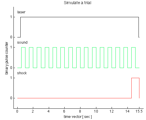
We have just received a chassis NI SMU-1073 with an SMU-6361 OR switched in PXI1Slot2 and a shielded connector BNC-2111. Aims to generate trains of three TTL pulses to control a laser, sound and shock via Matlab Application. I use the C OR-DAQmx API with Matlab MEX to integrate C in Matlab code.
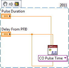
I came up with the following code in the examples in C to generate a pulse over TTL time-based train:
initialDelay float64;
float64 lowTime;
float64 highTime;
uInt64 periodsPerTrain;
float64 taskMaxTime = (lowTime + highTime) * periodsPerTrain + 2 * initialDelay;Configure Pulse
DAQmxErrChk (DAQmxCreateTask ("", & taskHandle));
DAQmxErrChk (DAQmxCreateCOPulseChanTime (taskHandle, "PXI1Slot2/ctr0","", DAQmx_Val_Seconds, DAQmx_Val_Low, initialDelay, lowTime, highTime));Configure the Pulse Train
DAQmxErrChk (DAQmxCfgImplicitTiming (taskHandle, DAQmx_Val_FiniteSamps, periodsPerTrain));Departure Train
DAQmxErrChk (DAQmxStartTask (taskHandle));Wait for execution
DAQmxErrChk (DAQmxWaitUntilTaskDone (taskHandle, taskMaxTime));Clean
DAQmxStopTask (taskHandle);
DAQmxClearTask (taskHandle);I'm stuck with two problems:
1.) SMU-6361 has 4 meter signals ctr0-3. With the above code, I can generate separate tasks for each TTL signal and evoke them consecutively with DAQmxStartTask. But in this case, I guess that the tasks are not synchronized. Can I use the clock signal to synchronize the other 3, for the tasks of each is triggered at the same time? What will be the right way to do this with the C API? The step of the smallest of the discrete-time in the example is 500ms. see the picture as an attachment to check how the TTL signals should look like.
(2.) what is my physical connector on the BNC2111 to outsource these signals.
/ PXI1Slot2 / ctr0-> PFI12/P2.4
/ PXI1Slot2 / ctr1-> PFI13/P1.0
But what ctr2 and ctr3? How can I configure the physical connector outsource? Is there a function to specify that?
Thank you in advance for any advice, suggestions and directions!
see you soon,
go9kata
Hello go9kata,
for your second question, with the BNC-2111. You can route the signal from the counter for
lines PFI avialable on the block of connection BNC 2111 with the following syntax
DAQmxErrChk (DAQmxSetCOPulseTerm(taskHandle,"/Dev1/PFI0"));
I hope that helps, if not please let me know.
Maybe you are looking for
-
I can not switch to Firefox 3.6.6 because cannot find license file
I am running Firefox 3.6.3. The upgrade process fails to install a partial update. When attempting to install a complete upgrade he says he can not find the license file and does not continue the installation. This has happened A few times a week ==
-
Ideas: You have problems with programs Error messages Recent changes to your computer What you have already tried to solve the problem Remember - this is a public forum so never post private information such as numbers of mail or telephone!
-
No Audio device is installed error message at startup
Problem title: original sound in Window Vista Why everytime I turn on my laptop, my sound says "no Audio device is installed"?
-
Security of my e-mail contact lists
Someone sends spam through my contact list using my e-mail address. How can I stop this? Sometimes when I'm offline and my computer is turned off.
-
My colleague and I are editing our first UCCX Call Center Script to include Spanish. Help
My colleague and I are editing our Call Center the existing script maps. This is our first attempt to script UCCX. They need to break the script in 2 locations, one that already exists for English and a copy of the menu for a Spanish version. We hav