trying to trigger multiple analog measures with each pulse of an encoder 500PPR
I'm taking steps analog multiple sensors to formula 6 with each pulse of a 500 ppr encoder and write these to a file. I met problem is I don't get 500 readings with 1 revolution of the encoder the more I received is 187 but is not consistent.
using
Card series E 6024
EIB L25G encoder
Still relatively new to labview as well as using an old version 7.0
Thanks in advance
Never mind after watching it somemore I found that I was using the wrong sampling frequency
Tags: NI Hardware
Similar Questions
-
I use the outgoing/incoming analog DDK with the DAQ 6341 SMU map.
The examples, for example aoex5, show a single timer (method outTimerHelper::loadUI), but the example shows the DMA loaded with same size of vector data.
There is a comment in the outTimerHelper:
 call rogramUpdateCount, which implies that memory sizes different pad per channel can be used.
(the comment is: switching between the sizes of the various buffers is not used)
Nobody knows what should be the format the DMA buffer for data from multiple channels with different frequencies?
For example, we want a0 with a sinusoid at 1 kHz and a1 with a sine wave of 1.5 Khz. What looks like the DMA buffer?
With the same frequency for each channel, the data are interleaved, for example (ao0 #0, ao1 #0; ao0 ao1 #1, #1,...), but when the frequencies for each channel is different, what the stamp looks like?
Hello Kenstern,
Data are always intertwined since each card has only a single timing for each subsystem engine.
To AO, you must specify the number of samples that will be released to the AO. You also specify the number of channels. Because he didn't is that a single engine timing for AO, each AO will be channel will be updated at the same time to update clock tick. Data will be interlaced exactly as shown in the example because each channel AO needs output at each tick of the clock to update. The data itself can change depending on the frequency you want to copy.
kenstern wrote:
For example, we want a0 with a sinusoid at 1 kHz and a1 with a sine wave of 1.5 Khz. What looks like the DMA buffer?
With the same frequency for each channel, the data are interleaved, for example (ao0 #0, ao1 #0; ao0 ao1 #1, #1,...), but when the frequencies for each channel is different, what the stamp looks like?
In your example, you must come with an update rate that works for the two waveforms (sine waves of 1 and 1.5 KHz). To get a good representation of a sine wave, you need to update more than 10 x faster than your fastest frequency... I would recommend x 100 if possible.
Update frequency: 150 KHz
Channels: 2
Then create you stamps that include complete cycles of each wave you want to produce based on the frequency of update. These buffers must also be of the same size.
Buffer 1: Contains data for the sine wave of 1 KHz, 300 points 2 cycles of sine wave
Buffer 2: Contains data for the sine wave of 1.5 KHz, 300 points, 3 cycles of sine wave
You can Interleave them as before. When the data are performed through the ADC, they are out different sine waves, even if the AO channels are updated at the same speed.
-
the analog inputs with digital edge trigger
I am currently triggering a readout with a digital trigger using a 0 - 5v as the digital source encoder. I am running LV 8.2.1 DAQmx 9.0 and a PCI-6259. I use a VI I wrote and which is very similar to 'Acq & chart voltage-Ext Clk.vi', and using the one-pulse encoder connected to PFI8 as the clock source for the sample clock vi. The only major difference is using the channel of the Z-trigger as a software reset inside the While loop with the DAQmx reading. Currently, the sample clock doesn't allow that either read the lower edge or an increase of PFI8, so I get a sample by one-pulse.
I need to double the rate of analog playback for a given tree rpm and encode them, so I need to read on the fronts and edges of the one-pulse encoder. The sample clock can be reconfigured for the detection of changes and still read the PFI8 port to increase and decrease as inputs of physical channel, or do I have to configure detection of modification of the task/digital input for a single line and use the "ChangeDetectionEvent" as the source for the sample clock HAVE? Detection of Timing/change DAQmx can still use the signal in PFI8, or should I use DI ports, and which ports are DI should I use?
Thanks in advance!
In fact P0.8 is. I was looking at the pinout for the 6251, no 6259. Sorry about that.
-
Analog inputs measures with NI6229 using the DAQmx driver
Hello
I have four different analog inputs connected to ai0 to HW 6220 ai3. I read these values with a single task, all 4 channels assigned to this task. When ai0 reads 7V, I see 0.8 V ai1 too, but I expect to be measured 0V. If I just assign ai1 to the task and measure all 4 channels, then I measured 0V as expected (although ai1 contains 7V, I just don't measure it).
Another comment 'funny', is that if I change the order in which I add channels to the task, measurement errors are different.
However, when measured with a multimeter 4-channel show tensions as expected.
Given that my calling task is can not block, I call the function
DAQmxReadAnalogF64 with timeout = 0 and numSampsPerChan = 1.
Any help is appreciated.
Thank you
Kind regards
Deepa
Deepa,
Thanks for the code snippet.
When you call DAQmxReadAnalogF64 the first time and you set a value of timeout of 0, there is a chance that the acquisition is not yet initialized. This is the expected behavior and should not be a problem. If the timeout error died at the first call, you might ignore it or set a different expiration time for the first call only. In all cases, you should drop the first value and start with the second value.
Jochen
-
I was converting pdf to word. I tried to download multiple documents, but the system froze. I closed the Acrobat Reader. Now, I see no export tools more. I even tried to restart the computer. I am currently with my account.
Hi bulldogcl1,
Please perform this cleanup tool to uninstall the reader Download Adobe Reader and Acrobat cleaning - Adobe Labs tool, reboot your system & install the latest Adobe Acrobat Reader DC Acrobat Reader DC Learn & support , sing with your Adobe ID to use the export to service PDF format using Acrobat Reader. Export PDF to Acrobat Reader DC.
You can also use this online https://cloud.acrobat.com/exportpdf service
Let me know if it solves your problem.
Kind regards
Nicos -
LiveCycle ES4. I am trying to move a picture online with a text box to create a header. I had to create a subform that flows to generate multiple pages of text. After changing the settings, it seems that I can't place the images and the text I would like. I tried moving them to the bottom, but does not work. Is there a way to encapsulate the images so that they can be places as much as I want?
Select your photo and text inside the subform flowed. Right-click and select wrap in subform do the positioned Subform subform. This will allow you to move objects in this subform positioned the way you like them.
-
How to trigger SMU - 6363 AI with the PXI-4142
Hello
SMU-1082
SMU-6363
SMU-4142
LabVIEW 2012 SP1
Hello
I'm trying to trigger action (SMU-6363) analog input with my SMU (SMU-4142). The API OR-DCPower has a VI called VI of Signal to export, that I could use to export the trigger signal in a specific line when 'Complete the event Source' comes up on my EMS.
The problem now is that i ' v tried several lines to transfer the signal to the SMU-6363, but unfortunately I still have an error of DAQmx. Has anyone tried similar before sync? Which internal lines I have to use to get this working? I'm just not producing a moment of tension at the time that the EMS (Single, Point). After SMU has defined the level it must send the trigger for SMU-6363 who would then measure the external signals constantly.
Thanks in advance!
-henkkaHello
I solved the problem of routing measure relaxation of SMU with Signal.vi export online PFI0 of SMU-6363 (SMU 3 channel). Then I started every other SMU channels (0:2) with this signal to trigger by using the configuration digital edge measure Trigger.vi (the VI input terminal is PFI0).
I configured the data acquisition sample clock to use the PFI0 as a source of the clock. With this method I am able to measure sinus 2 kHz generated with four channels EMS individually with my DAQ without no phase shift (0.1 degrees) between own EMS measurement and data acquisition.
Hope this helps anyone with the same kind of problem.
Best regards
-Henry
-
Measures with the date Conference
Hello
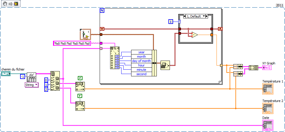
I have to make an application, as part of my end of study project, which allows to calculate heat flow. Pour this, I have data measured with thermocouples. These data are stored on a data recorder that record these data on a .txt, .xls or .csv file (it is to be chosen by user).
I'm not very chiseled with LabVIEW.
In a Prime Minister, I tried to read the .txt file data. I can read the 1st line as I wish but not others.
So I decided to work with a .xls file. The temperatures Conference goes smoothly. For time is the date, it's more complicated. Indeed, I would like to USE date and time corresponding to each measure to plot a graph XY with the date and time X and Y the temperature of the thermocouple.
Kind regards
Here's an example (VI from LV2011 but attached VI en LV2010) made on the basis of your code. Comment by watch it extract the news date and time of the string and generate the the from graph XY time in seconds in X. realized very quickly, it is without doubt room for improvement but you will serve as a basis for work at least.
To define 'Structure box' serving at first as far as being 0 and calculate relative time to the following samples. Thus the x-axis of the graph starts at 0.
My time is short, I renounce other comments but I happy to answer specific questions.
-
read the multiple analog inputs at the same time
Hi all
I use USB-6001 and want to develop an application to multiple tasks in C++. I try to read several analog inputs at the same time, but got some errors. To put it simply, I copy one of the sample code to read in analog data in a channel, and then turn it into function. Then I call this function to thread with the names of different poles (for example Dev1/ai0, Dev1/ai1) and I come across this error:
"The specified source is reserved. The operation can not be specified such complete"code of State-50103
I have search the forums, this may be because I use the hardware timing in this function, and this material timing cannot be used simultaneously by multiple tasks. I may have to put all the lines, I want to read in a single task (such as Dev1 / ai0:1). This way I can read two lines at the same time. However, when I try this, I encounter another error:
Status code "buffer is too small to contain the data read" - 200299
So here is my question, what should I do if I don't want to read the multiple analog inputs at the same time? Is the thing that hard time cannot be used by several true task? If I have to read several lines to a single task, how to set the settings?
-
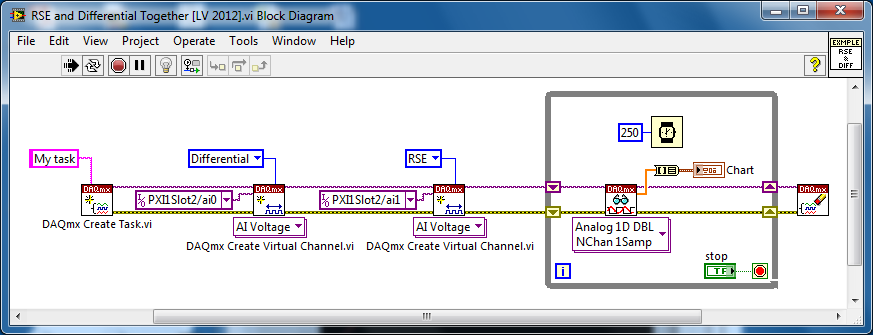
Several analog inputs with different configuration differential/CSR
Hello
Can anyone tell how to measure two analog inputs with different configurations using a USB-6009?
I am aware of the syntax for create virtual channels for the channels DAQmx create virtual so I created two strings using Dev3 / ai0:1 but I would like the first string of the CSR and the second to be differential.
So far I have found no way to specify the configuration of the separate channels.Any ideas much appreciated!
Jack
JackT wrote:
I prefer to use the 'low' level vi is therefore always curious to know if there is a way to set the configuration using the their.
It should be like this:
-
PCI 6259 - Trigger HAVE voltage measurment when P0.31 varies from low to high
I write a model that uses the output digital (P0.8 - P0.31) and you want to trigger a tension measured on AI16 when P0.31 varies from low to high. Any ideas on how to achieve this?
Almost what Michael said...
michael_lewis23 wrote:
Have you looked at an example in the finder for example LabVIEW? You can export a digital signal connect your p0.31 signal using a wire to a PFI line on the DAQ card. For a task of analog input, you can place a DAQmx Start Trigger VI and choose the use a clock source external sample under the line of PFI where the digital signal have been exported to.
Best regards
-
How to measure my each operating time blocks
Hi, guys
I will measure my each main blocks, duration, are totally five large blocks in my final VI, the last four of them were in a while loop
Thank you
What exactly do you mean by "block"? Is this a Subvi, primitive LabVIEW, a piece of LabVIEW code?
You can use several functions of number of cycles. If you put your code in a flat sequence structure with Tick account in settings in the meantime, you can subtract the values from each other and to relative time of each piece of code.
Why are you worried about the execution time? Problems of particular clock? Most of the LabVIEW primitives will run so fast, you'll probably see no or very little change in the number of cycles before and after them.
Here is an example to show how measuring the execution time for a section of code.
-
ASA - Tunnel all traffic, allow rays to communicate with each other
Well, I hope someone can help me with this headache! Switching to employ a PIX and VPN 3005 concentrator Office at home in an ASA5510 for firewall and IPSEC tunnels. It is pretty much a
- VPN on a stick, multiple rays.
- All traffic sent by tunnel
- Internet access through main office (using the web filter) of
- VOIP to VOIP between rays
- All departments are using the clients VPN 3005 HW or ASA 5505 s
HEADQUARTERS: 10.0.0.0/24
Speaks 1: 192.168.11.0 / 24
Speaks 2: 192.168.12.0 / 24
Speaks 3: 192.168.13.0 / 24
-continues to 192.168.31.0 / 24
Spoke with the current configuration, 1 can communicate with all the resources in the home, office and Internet integrated properly checked by a tracert. However, the rays cannot communicate with each other. This is required for VOIP traffic, when all TALK TALK calls are made (sites).
Logging information when talk of talks initiated icmp:
- No group of translation found for icmp src, dst outside: 192.168.31.1 inside: 192.168.11.1 (type 8, code 0)
If I remove the nat (outside) 1 192.168.0.0 255.255.00 - rays will begin to respond to each other, but then the rays cannot tunnel through the Home Office Internet traffic. My brain is so scrambled after the cramming of VPN configurations for these days, so I hope someone has an idea. I've always used concentrators 3005, so it's a little different! In the search for documentation for this configuration, I was surprised that this isn't a most common topology. It seems that this article would (http://www.cisco.com/en/US/products/ps6120/products_configuration_example09186a00805734ae.shtml), but there is no rays! In any case, I'm sure this has something to do with NAT rules and perhaps who need access for traffic list speaks of talking.
=============================================
ASA Version 8.2 (1)
!
hostname asa5510interface Ethernet0/0
Speed 100
full duplex
nameif outside
security-level 0
IP address 97.65.x.x 255.255.255.224interface Ethernet0/1
Speed 100
full duplex
nameif inside
security-level 100
IP 10.0.0.40 255.255.0.0permit same-security-traffic inter-interface
permit same-security-traffic intra-interface
the DM_INLINE_NETWORK_1 object-group network
object-network 10.0.0.0 255.255.0.0object-network 192.168.0.0 255.255.0.0
access-list sheep extended ip 10.0.0.0 allow 255.255.0.0 192.168.0.0 255.255.0.0
Allow Access-list extended wccp servers ip host 10.0.0.83 a
Redirect traffic extended access-list deny ip any object-group DM_INLINE_NETWORK_1
Redirect traffic scope permitted any one ip access-list
Global 1 interface (outside)
NAT (outside) 1 192.168.0.0 255.255.0.0
NAT (inside) 0 access-list sheep
NAT (inside) 1 10.0.0.0 255.255.0.0Route outside 0.0.0.0 0.0.0.0 97.65.x.x 1
Route inside 192.168.0.0 255.255.255.0 10.0.0.1 1
Route inside 192.168.2.0 255.255.255.0 10.0.0.1 1
Route inside 192.168.3.0 255.255.255.0 10.0.0.1 1Crypto ipsec transform-set esp-3des esp-md5-hmac RIGHT
life crypto ipsec security association seconds 28800
Crypto ipsec kilobytes of life - safety 4608000 association
Crypto ipsec df - bit clear-df outdoorsCrypto-map dynamic dynmap 1 transform-set RIGHT
map mymap 65535-isakmp ipsec crypto dynamic dynmap
mymap outside crypto map interface
crypto isakmp identity address
crypto ISAKMP allow outside
crypto ISAKMP policy 5
preshared authentication
3des encryption
sha hash
Group 2
life 86400crypto ISAKMP policy 10
preshared authentication
3des encryption
md5 hash
Group 2
life 86400crypto ISAKMP ipsec-over-tcp port 10000
management-access inside
a basic threat threat detection
no statistical access list - a threat detection
no statistical threat detection tcp-interceptionWCCP web cache redirect-list Redirect-traffic group-list password xxxxxxx wccp-servers
WCCP 90 redirect-list traffic Redirect wccp servers group-list password xxxxxxxWebVPN
internal MJHIvpn group strategy
attributes of Group Policy MJHIvpn
value of server WINS 10.0.10.1 10.0.10.2
value of 10.0.10.1 DNS server 10.0.10.2
allow password-storage
Split-tunnel-policy tunnelall
mjhi.local value by default-field
allow to NEMusername field-3002 SjfS1Pq2xZGxHicx encrypted password
attributes of username field-3002
VPN-access-hour no
VPN - 250 simultaneous connections
VPN-idle-timeout no
VPN-session-timeout no
Protocol-tunnel-VPN IPSec
allow password-storage
type of remote access serviceremote access to field tunnel-group type
General-field tunnel-group attributes
Group Policy - by default-MJHIvpnIPSec-attributes of tunnel-group field
pre-shared-key *.class-map inspection_default
match default-inspection-traffic
!
!
type of policy-card inspect dns preset_dns_map
parameters
message-length maximum 512
Policy-map global_policy
class inspection_default
inspect the preset_dns_map dns
inspect the ftp
inspect h323 h225
inspect the h323 ras
inspect the rsh
inspect the rtsp
inspect sqlnet
inspect the skinny
inspect sunrpc
inspect xdmcp
inspect the sip
inspect the netbios
inspect the tftp
inspect the they
inspect the icmp
!
global service-policy global_policyHello Ala,
In Act got to be with the Nat configuration.
So basically you want to tunnel the traffic on the rays to communicate with each other.
OK, it would be with a nat 0 with the access list with the corresponding traffic outside.
Also on the crypto ACL for each site configuration, you must add an entry for the traffic of other offices.
I hope that I have explained myself.
Have a good
Julio
Note all useful posts!
-
I want to create a Web site with 4 child pages that interact with each other when opened separately on 4 different computers.Is this possible?
Example:
Child 3-page Web site open on 3 different computers with triggers and the following objectives:
PC #1 - child #1 - confirm button (trigger)
PC #2 - Page #2 - accepted Confirmation Popup, resulting by clicking on 'confirm' page computer/child #1 (target)
PC #3 - child Page #3 - calendar Popup changed, resulting by clicking on 'confirm' page computer/child #1 (target)
Any ideas are much appreciated.
THX.
No this is not possible with Muse.
-
How to install VMplayer 3 network for virtual machines to comminicate with each other?
People,
Hello. I use VMPlayer 3.
SE host: Windows 7
Comments to: Windows XP and Oracle Linux 5I need to set up the network and activate Windows XP communicate with Oracle Linux 5.
I followed this tutorial http://www.vmware.com/support/ws5/doc/ws_devices_serial_2vms.html to configure 2 virtual machines in Windows 7 host machine.
I tried to test 2 virtual machines in the way as below:
In Linux, [user@localhost ~] $ping WindowsXP_HostName
Release: Unknown host WindowsXP_HostName
At the Windows XP command prompt:
C:\ping localhost.localdomain
Its release: ping localhost 127.0.0.1 with 32 bytes of data...
Reply from 127.0.0.1: bytes = 32 time = 2ms TTL = 128
He meets a few times and then disconnected by itself. It seems that Windows XP is ping itself and not Linux server. The host name of the Linux server is 'localhost' as well. It is a kind of confusion for me.
From the information above, we can see that 2 VMs cannot connect between them.Can any folk provides a tutorial or example or case study to set VMPlayer 3 allowing 2 virtual machines communicate with each other by step?
Very grateful in advance.
In the guest machine, all I see is click on VMplayer-> VM-> settings-> network-> Network adapter Connection-> select Bridged: directly connected to the physical network. After that, nothing to keep.
That's it for the network card in Virtual Machine of its parameters, and the rest is done to each guest at the guest OS level.
In Windows 7 host machine, I don't see anything first.
What we need to do is to assign 3 IP addresses to 3 machines: Win 7, Win XP Guest and Linux host.
Why the world can't bring you up Google in a browser and type, the ip static windows xp, then static ip rhea of windows 7 and finally static ip. As I have already said there are more then enough tutorials on the Internet about how to configure a static IP address by a given operating system then I suggest you Google it! It makes absolutely no sense to write the instructions step by step for you when there are already dozens of tutorials available on the internet.
Maybe you are looking for
-
How to connect Blue Yeti to IPad Mini 2?
I just took advantage of a big sale at Best Buy to pick up an IPad Mini 2 32 GB to use with my Blue Yeti mic. However, looking at the connection options, I don't know if the lightning to the USB Camera connection kit works with it because some critic
-
Hi... I get this every time I try to open a specific application in my system. Could you please suggest how we can avoid this error message. Thank you.
-
I can't access my windows management instrumentation software in order to use the restore of the system because some of my files of windows management has been moved or is missing. where can I find them that I just want to be able to use the system r
-
Print via Wi - Fi from a Blackberry Handheld
Anyone know if it is possible to print from a Blackberry 8900 to a Photosmart C4500 via a wireless connection? Concerning Gareth
-
I can't play all YouTube uploaded Media Player .mp4 files
I can't play all YouTube uploaded media player... .mp4 files all the Codecs are installed, help me...