two drivers of PXI chassis with Configuration problem
Hello
I have two PXI chassis. One is PXI 1033 and works perfectly with the NI PXI-5404, 5105, 6509, 1409, installed 8336. The other is 1036 PXI with the PXI-5404 NI, 8366 installed. When I was trying wreath connect, as master 1033, 1036 as slave, I found several problems.
1. in the Measurement & Automation Explorer, does not have my good guys in 1033. Instead, there is a sign of the Red Cross in bottom right with 6509, 5105, 5404.
2. I can't find an another 5404 of the 1036. In fact, I can't find 1036 in MAX.
Update BIOS. My PXI system is already identified under the name 'NOR PXI - 1033 Embedded MXI Express' and Chassis1 is identified as 'NOR PXI 1033'.
So I made several tests as below:
1. unscrew the 5404 1036 slave. MAX can configure 2 1036 chassis. Ok. But when I reconnect 5404 in 1036, same result happened as stated above.
2 uninstall the driver of 5404, so the 5404 in 1033 does not either now. And then reboot again, same result happens again. Cannot detect the 1033 chassis. Other vouchers in 1036 don't work either.
Please, any suggestion is highly appreciated.
Sincerely,
Bin
Hi Ben,
This happens sometimes with MXI-Express:
Error code 12 with MXI-Express
http://forums.NI.com/T5/PXI/two-PXI-chassis-connection-with-configuration-problem/m-p/1475876#M9033
In general, you can read this error 12 means on Device Manager:
Explanation of error codes generated by Device Manager in Windows XP Professional
http://support.Microsoft.com/kb/310123
If it was a problem of bandwidth, PCI or PXI side, you could pull a few cards to see if that alleviates the problem, or that the link from Microsoft over the States, you can disable the driver for other cards.
Tags: NI Hardware
Similar Questions
-
PXI chassis with remote hot-plug
Hello
I use the SMU-PCIe8371 with SMU-8370 remote control instruments in the SMU-1075 chassis in Vista. In order to see my instruments in MAX the chassis must be turned on when I reboot Windows. If I disable the chassis while Windows is running, I have to restart to be able to reuse the instruments.
Is it possible to make MAX see the chassis if it was not executed when Windows started or has been disabled while Windows is running?
Thank you!
Hello
You can disable and enable the bridge PCI to PCI in the Device Manager, but this is not recommended or supported. I also suggest that you turn off the chassis while Windows is running, which is essentially the same as the withdrawal of a card PCI of your computer while the PC is on. This can lead to problems with your system, such as the database of MAX, which isn't very fun to solve. The recommended method to start your system is always chassis first, followed by the PC, and to stop, is PC first, followed by the chassis.
-
I have a PXI chassis with a PXI-8101 controller. It is equipped with a system of operating in real time. I connect to it on a PC with a Windows operating system. I am trying to send my PXI system variable length string messages to my PC.
On the PC, I have a LabWindows application that allows you to send and receive data with the PXI system. I'm trying to send the PXI system error messages to the PC on ethernet. I am able to send digital data between them, but not the string messages. The PXI software meets the CNVCreateArrayDataValue() function call and not to her, but never returns. There only have this problem when the CNVDataType parameter is CNVString; When I change the CNVDataType to CNVBool it doesn't have this problem. I'm new on this time real PXI so would appreciate the help. Here is the code on my PXI system that sends these text messages.
At the beginning of the RTMain, I create the writer
CNVCreateBufferedWriter ("\\\localhost\\system\\" REG_CAL_ERROR_STRING, 0, 0, 0, 64, 5000, 0, & gErrorPublisher);
Then I call a function with a string in the list of parameters:
void SendRT_ErrorMessage (char * message)
{
Data CNVData = 0;
int error;
error_str char [256];
int i;
char out_str [ERROR_STRN_SIZE * 4];
strcpy (out_str, message);
size_t arrayDims = ERROR_STRN_SIZE;
arrayDims = strlen (message) + 1;
error = CNVCreateArrayDataValue (& data, CNVString, out_str, 1, & arrayDims);
If (error<>
{
strncpy (error_str, CNVGetErrorDescription (error), 256);
}
CNVPutDataInBuffer (gErrorPublisher, data, 1000);
CNVSetArrayDataValue (data, CNVString, out_str, 1, & arrayDims);
CNVPutDataInBuffer (gErrorPublisher, data, 1000);
CNVDisposeData (data);
}
Change this:
public static void CVICALLBACK ErrorMessageCallback(void * handle, CNVData data, void * callbackData)
{
char message [ERROR_STRN_SIZE];CNVGetScalarDataValue (data, CNVString, & message);
(void) SetCtrlVal (panelHandle, PANEL_TEXTBOX_DEBUG_MSG, "got something\n");
(void) SetCtrlVal (panelHandle, PANEL_TEXTBOX_DEBUG_MSG, message);
(void) SetCtrlVal (panelHandle, PANEL_TEXTBOX_DEBUG_MSG, "\n");CNVDisposeData (data);
}
To do this:
public static void CVICALLBACK ErrorMessageCallback(void * handle, CNVData data, void * callbackData)
{
char * message;CNVGetScalarDataValue (data, CNVString, & message);
(void) SetCtrlVal (panelHandle, PANEL_TEXTBOX_DEBUG_MSG, "got something\n");
(void) SetCtrlVal (panelHandle, PANEL_TEXTBOX_DEBUG_MSG, message);
(void) SetCtrlVal (panelHandle, PANEL_TEXTBOX_DEBUG_MSG, "\n");CNVDisposeData (data);
}
You also need to add CNVFreeMemory to free the memory allocated for the string.
-
Is it possible to route signals of relaxation between two chassis PXI-1002 with the PXI-8335?
Hello
as the subject says, I am interested in the delivery of a signal to trigger between two chassis PXI-1002. At present, these two chassis are connected by a MXI - 3 system using maps PXI-8335. The software is Labview 2010 sp1 and 380 NIScope drivers.
We want to keep (a PXI-5122 by chassis) scanners supply separated due to the requirements of our measure! The chassis are connected via cable to fiber optic. This explains why I can not just use the shutter release in Star, or connect via 'Trigger' or 'clk' cards (the inputs / outputs to the front of the cards).
I found a few examples, but they seem to all be designed for use with a chassis only, I'll call later to the examples that inspired me to this point. Each guide explaining the synchronization of several chassis systems seems to use another material or VI is not accesible to me. This makes me wonder if my hardware has the capacibilities I need.
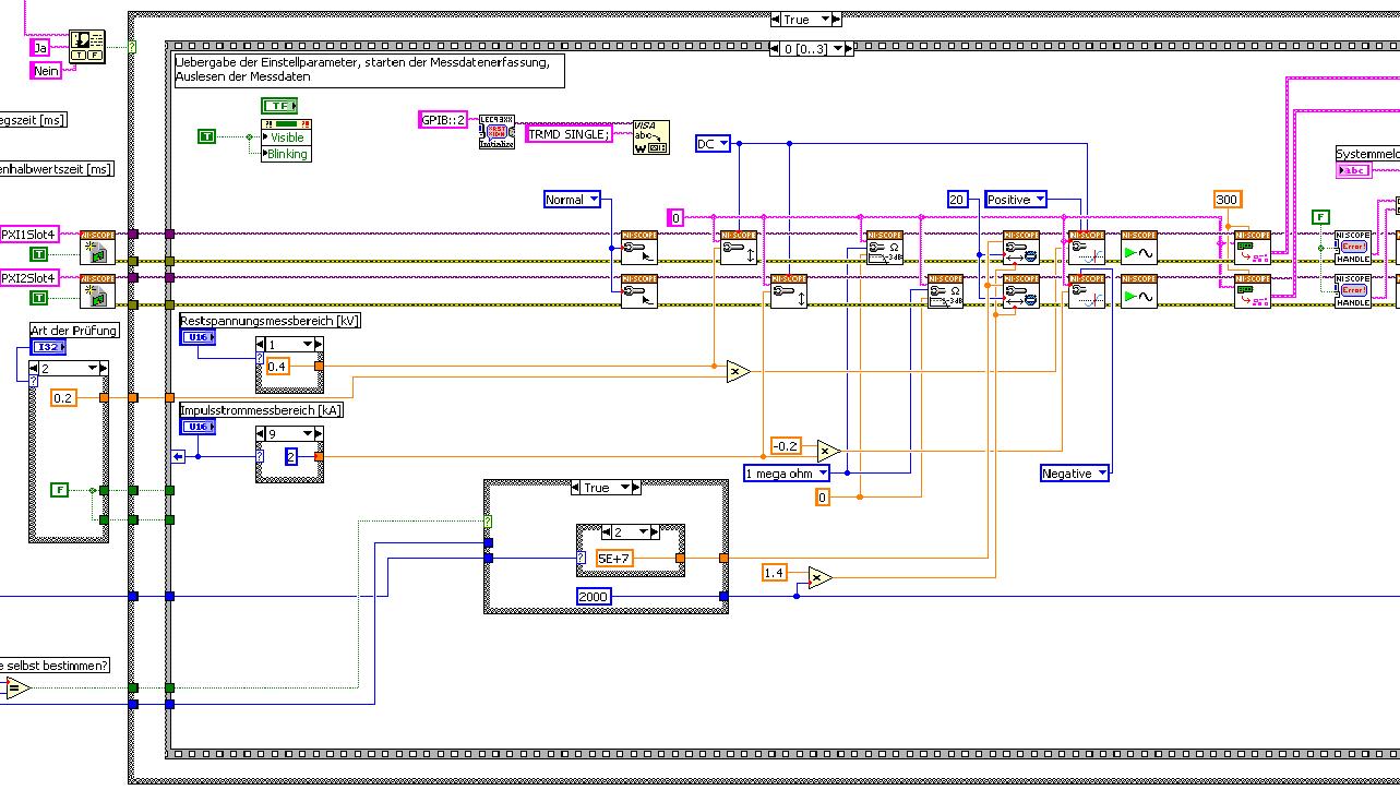
The first picture shows approximately where I started from (sorry I can't post VI, confidential...):
Only the middle part is interesting. Two sessions are initialized and manipulated parallel, trigger too. This has led to delays in the signals and should now be fixed. This apart from the VI works fine.
Goal is to trigger only on one channel but both devices! If possible, the device will trigger must be chooseable.
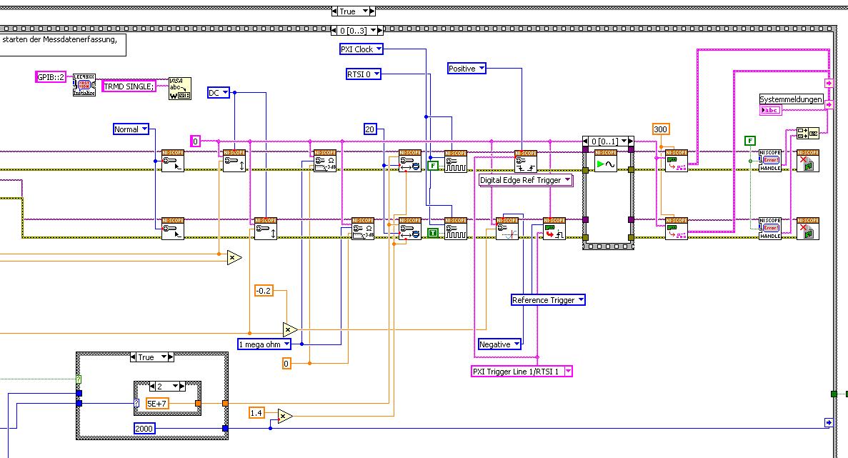
I started to rebuild the VI using the "EX Synchronization.vi 5xxx niScope' seeming spontaneity. The result is shown in the following image:
I tried different RTSI lines, but had no positive results. only the main channel has triggered.
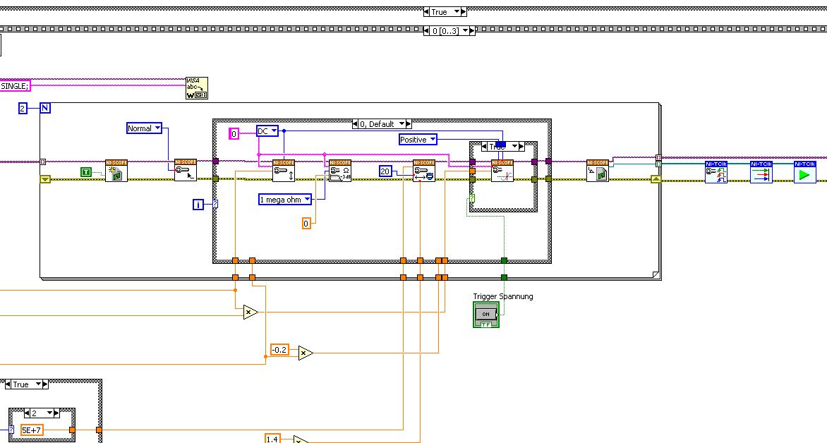
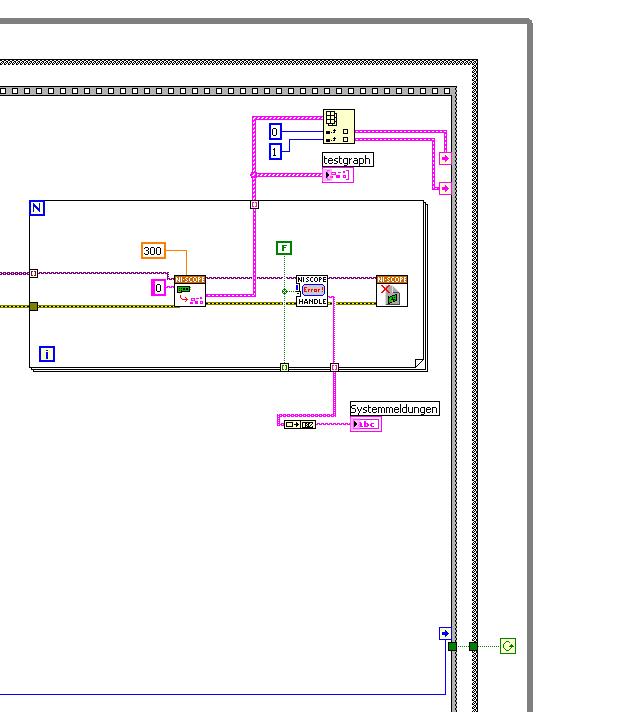
After this first approach, I looked in the "niScope EX .vi multi-Device configured Acquisition (TClk)" and other examples of TClk which seem to work for similar problems. The VI of reconstruction can be seen in the following images:
(Sorry, I had to use two photos..)
In this case, I didn't have no choice for trigger lines, it would automatically set the VI TClk. I tried to trigger on both devices, though. This second approach seemed promising to me, but it was an error:
"niTClk Synchronize.vi:1".
Index (starting at zero) of the session: 1
The error reported by the pilot of the instrument:
No registered trigger could be found between the
devices on the route.If you have a PXI chassis, the chassis correctly identify in
MAX and make sure that it has been configured correctly. If you use PCI
devices, make sure they are connected with a RTSI cable and that the cable RTSI
is saved to the MAX. Otherwise, make sure that there is an available trigger line
the trigger bus shared between devices.Source device: PXI1Slot4
Target unit: PXI2Slot4
Status code:-89125niTClk Synchronize.vi:1
Index (starting at zero) of the session: 1
The error reported by the pilot of the instrument:
No registered trigger could be found between the
devices on the route.If you have a PXI chassis, the chassis correctly identify in
MAX and make sure that it has been configured correctly. If you use PCI
devices, make sure they are connected with a RTSI cable and that the cable RTSI
is saved to the MAX. Otherwise, make sure that there is an available trigger line
the trigger bus shared between devices.Source device: PXI1Slot4
Target unit: PXI2Slot4
"Status code:-89125"
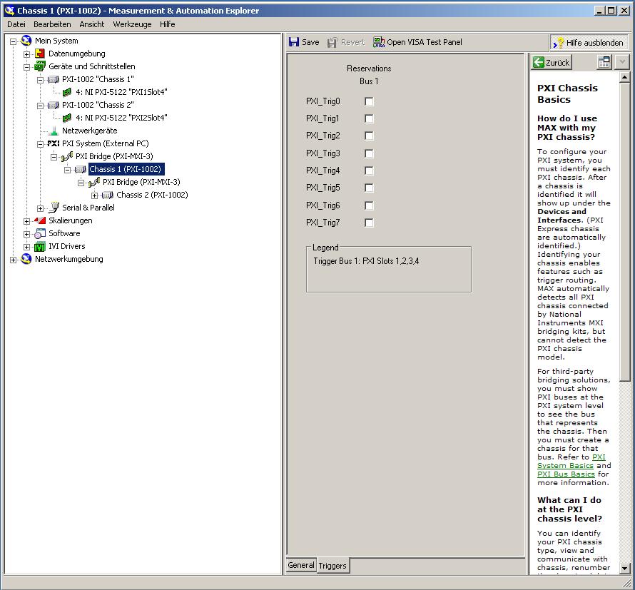
This error came back even after I've identified this drug as possible to the MAX, as shown in the screenshot:
In some of the textbooks, they showed how to get the MAX trigger lines, but as you can see, there is only booking options in my MAX. Whatever I do, I can't find options to define how to get my trigger signals...
In principle, it is possible to trigger instruments in different chassis, which is indicated in this Guide and others... the question that remains is can it be done with my set of components?
I understand that the use of multichassis compromised the integrity of the lines very adjusted as trigger in Star etc., so the configuration should be taken into account in some way, that my approach does not, I knew... But there must be a way to do this? And to start: to get just any signal from one device to the other trigger!
For any advice on this issue, I would be very thanfull!
Concerning
Max1744
Hi Max,.
Thanks for the detailed post and explanations of your application and requirements. You're right using TClk, because this is the optimal method to synchronize the 5122 digitizers. The original VI you worked with is unique for some of the legacy scanners and does not directly work with scanners based on the most recent CMS (for example the 5122). The good news is that you can synchronize these cards to separate chassis, but it will use the calendar 66xx and synchronization (T & S) cards in the chassis of the master and the slave, as indicated in the guide that you have accessed. These are needed because a common reference clock must be shared between them as well as a couple of tripping. MXI itself can not handle export triggers and clocks, so there is no way to do this without physically wiring between the chassis with cards T & S. Unfortunately, regardless of what specific method, you use for synchronization, it will take a material extra beyond what you currently have.
As one of your needs looks like it is necessary to retain wiring between the chassis directly, you may need to consider to synchronize using 1588 or GPS protocols. 1588 Protocol is a system for synchronization on the network while GPS course use antennas and locks for a common wireless signal. Although these synchronization methods may allow you to keep your chassis isolated, they will also require some manual configuration because you would be able to use the TClk synchronization and so the level of synchronization you can get between the cards may not be as good that can physically wire signals between the chassis using T & S cards.
Hope this helps,
-
Connecting two pxi-2527 with NI Switch Executive
Hello world
I want to build a test equipment to measure the resistance of the wires. My stock of material contains two cards-MUX pxi-2527 and a pxi-4070 DMM. Each pxi-2527 is connected (via a TB-2627) of a cable harness of the 26 son (name of the harness "6YDA" and "6YDB", see photos).
The two beams is absolutely equal in the Assembly and naming (for example the sons are named from A to Z).
First of all, I want to set up a self test function. For this purpose an adapter was built to connect the two cables to driver.
The adapter connect cable A to the first harness with cable A second son, the first B b to the second and so on.
For the auto test, simply measure the resistance of adapted connections 26.
Now I tried to create a virtual device with roads and routegroups via Switch Executive and insert it in my LabView 2009 program.
But I m not sure if my virtual device is correct. (See pictures attached)
Unfortunately I have not found an example on the connection of two cards-MUX pxi-2527 together, I need your help.
I would be very happy to get help from you!
Thank you very much!
Greetings,
E Tec
Hi E-Tec,
Looks like you have already setup the roads and the routegroups in SwitchExecutive. Now let's launch LabVIEW and make some magic; Some examples of code that will test each routegroup:
The first thing we need to do is log on to your virtual device:
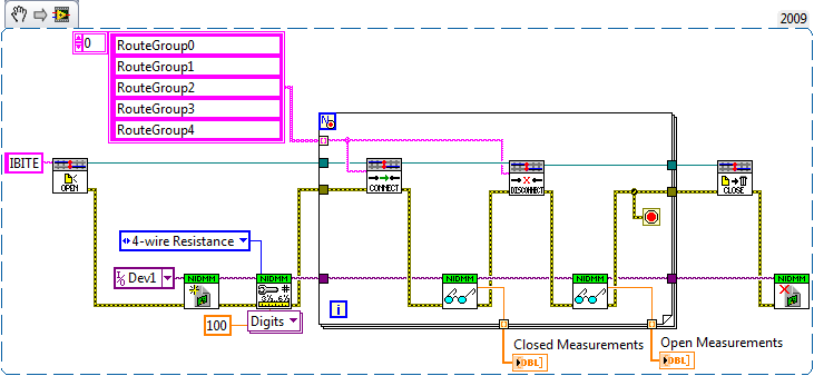
Then, you must configure our DMM and call certain route groups:
I made many assumptions on what we are trying to accomplish. My code does the following:
1. opening of the session for your named virtual device.
2. the opening of session for DMM... it has more parameters I have hidden for clarity. See DMM examples in help"Find examples | "" Material input and output"modular instruments and devices" NOR-DMM ' unique measures ' measure resistance if you want to see the entire feature set.
3 close your RouteGroups one at a time, measurement of resistance, opens the Routegroup, then measure resistance again. I put only the first 5 routegroups in this code.
Which should help you get started. Sorry to expect if a long time keep
 . Have a great day!
John Sullivan
Switch Product Support Engineer
National Instruments
-
How to install the version of nor-Sync 3.1 in the remote system (processor integrated PXI chassis) to recognize the PXI-6682 device to work with labview RT?
Hung Nguyen
Hung Nguyen,
The installation of drivers for all targets in real-time remotely is more or less the same. First install the driver (in your case the NO-Sync) on your PC, then install it on your system remotely through MAX. For step-by-step instructions, see install the software on your NI CompactRIO controller.
See you soon,.
-
Vista Home Premium (with many problems), I wish to go back to XP PRO. Where can I find the drivers? I do not think that the original XP disc also contains the drivers!
Some computers come with a disk drivers or Drivers and Utilities . If yours does not, look for drivers on the web site of the manufacturer of the computer.
-
I have trouble setting my local setup correctly with a mixture of regions with different configuration of persistence of disc. Is a configuration problem on my end or a bug in GemFire and/or Spring GemFire data?
The configuration of my work is as follows:
< gfe: replicated-region id = "replicatedRegion" cache-ref = "gemfireCache" disk-store-ref = "overflowOnlyDiskstore" persistent = "false" >
< gfe:eviction type = threshold "HEAP_PERCENTAGE" = "90" action = "OVERFLOW_TO_DISK" / >
< / gfe: replicated-region >
< gfe:local - region id = "localRegion" cache-ref = "gemfireCache" / >
With the above configuration, I can successfully call JSONFormatter.fromJSON (json) and get a reference to a PdxInstance object. However, when I kinda modify configuration to enable the persistence of drive on one of the regions, the call to JSONFormatter.fromJSON (json) fails. The change is as follows:
< gfe:local - region id = "localRegion" cache-ref = "gemfireCache" persistent = "true" disk-store-ref = "persistOverflowDiskstore"/ >
Without any additional modification, the following error starts occurring:
com.gemstone.gemfire.pdx.JSONFormatterException: could not parse JSON document: [Source: java.io.StringReader@5549f0e, line: column 26,: 6]
at com.gemstone.gemfire.pdx.JSONFormatter.fromJSON(JSONFormatter.java:66)
...
Caused by: com.gemstone.gemfire.pdx.PdxInitializationException: The PDX metadata must be persistent in a limb that has persisted data. See CacheFactory.setPdxPersistent.
at com.gemstone.gemfire.pdx.internal.PeerTypeRegistration.checkAllowed(PeerTypeRegistration.java:531)
at com.gemstone.gemfire.pdx.internal.PeerTypeRegistration.verifyConfiguration(PeerTypeRegistration.java:515)
...
Note that it is breaking while I try to get a reference to a PdxInstance, and if the code has not yet arrived at the point where I place a PdxInstance object in a region.
Thanks for any help in advance.
Hello
JSONFormatter PDX uses as is the serialization mechanism from the Gemfire cache. As indicators of error, you must have your persistent PDX meta-data when you use PDX with an area that itself is persistent. Adjust your configuration as follows:
It will use a default for PDX record store, but you can also use a specific store if you wish.
When you use PDX, a "PDXType" is created for each class serialized with PDX and this type id is stored with the data in the region. If this region is persistent, then the PDXType, associated with this object must also be kept.
-Jens
-
PXI-5112 with XP, LV 2010 (and the determination of review)
Just found an old PXI-5112. I could do great with this card things if I could make it work.
When I first plugged it to my PXI chassis, it was detected in MAX as a device of NOR-DAQ traditional with the latest version of NOR-DAQ traditional (7.4.4). However, when I tried to open a test Panel on this subject, I received a message that the device "failed the test". If I open the Panel test in any case, I get an error-10840 (soft error).
I called OR support on this subject and the engineer found this article in the knowledge base for me:
http://digital.NI.com/public.nsf/allkb/E956B50E8E0FC44E86256B030062CA2E
I then tried to determine my Board review. I read the first issue I've found which corresponded to the model. It was on a sticker on the side rear of the Council and read "702864 A-01". This vignette, we determined that my Board is A revision.
I tried following the advice that knowledge base article and install OR-DAQ 6.7.0 and 1.6 NO-SCOPE. With this combination, I can load up the SCOPE screws with LV 8.2.1, but when I try to run an example VI on my device, "DAQ::6", it fails to initialize the jury with "method or function not defined", or something like that. With NEITHER-DAQ 6.8.1 and 1.6 NO-SCOPE, I get a lot of impossible to find DLL errors attempting to perform the SCOPE of EIS. With NEITHER-DAQ 7.4.4 and 1.6 NO-SCOPE, I get the same old "Undefined function or method. If I try to run the VI on the wrong channel, like "DAQ::1", I get 'Device does not exist', he seems to recognize the device, just not being able to do something with it.
I'm about to give up on this, but I just realized that there are FIVE different numbers printed on my Board which match the pattern in this knowledge base article.
White sticker on chip on the back: 702864A - 01 Copyright 2000 NI
Yellow sticker on chip on the back: 703058A - 01
Printed in black on the login Panel: C 186030-01 REV1
Printed in white on the back of the PCB: 184196E-01
Printed in white on the front of the PCB: ASSY184194E-01
There is also a label with bar code with C3297D, which I think is the serial number. The guy NOR tried searching but couldn't find anything.
An interesting thing in particular on these numbers is that the ASSY184194E-01 contains the same exact number that is given as an example in this article in the knowledge base for a tray of Rev E: 184194E-01
I have two questions, if anyone can help:
1. does anyone here have a PXI-5112, Rev A or one E, in no case to work in Windows XP?
2. which one of these numbers should I trust to identify revision of my Board? It seems like that might be either A, C or E.
Thank you!
Max
Hey Maxwell,
You are right that the serial number is C3297D, and the part number for the Board should be 184194E-01, indicating that it is revision E and is a module of 16 MB/ch PXI-5112. When you got the error, you said you had traditional-DAQ 7.4.4, but I'm not clear what version of NOR-SCOPE, you had. OR-SCOPE has been installed in the system at this time?
If you plan to run this Board in LabVIEW 2010 on a Windows XP-based computer, you need to install OR-SCOPE 3.6.2 in order to get all the support you need. As long as you are running a 64 bit OS, the PXI-5112 should function normally. OR-SCOPE 3.6.2 is the oldest version of the driver that will support LabVIEW 2010 (it will support LabVIEW 8.5.1 and more later). Seems to me that previous errors, you have been doing are the result of incompatibilities between versions of your different software/driver. If you install this latest version of NOR-SCOPE, it must include all the right support you need (traditional-DAQ 7.4.4, OR-SCOPE 3.6.2 support for LabVIEW 2010, NOR-DAQmx 9.1.5, MAX 4.7, etc.). Unfortunately, the only way to get NO-SCOPE 3.6.2 is through the CD August 2010 device drivers (DCD). Once you start the installation, you can select always right to install NO-SCOPE and not the rest of the drivers in the package if you do not want. Of course, having the latest updates of all might not be a bad idea, or if you want to just install everything.
Moreover, all the part numbers you listed (except the last) are parts numbers for specific elements of the PXI-5112 (Panel connection, the real PCB, CPLD chip, etc.). The assembly number is the one you are looking for. Sorry for the confusion.
Best regards!
-
PXI chassis not found after reboot host
I use a chassis SMU-1073, Win7 and Labview 12.0f3 on the host. After a restart of the host, MAX is unable to find the frame and I need to reboot the host. Rebooting usually works, but often it is necessary to power down of the PXI chassis too. It is very tedious and time-consuming. There must be a way to simply restart the driver (single) and set things right after a restart of the host. Thanks for your help!
Hi bjuberchaub,
Let's see what crossrulz has to say about the race condition, but the situation you have described above does not sound like a driver problem.
Regarding "if I cycle power on the chassis and try to reconnect", we recommend strongly cyclical food your chassis when your computer is turned on. It is the equivalent to remove a PCI (e) card on a desktop while it is running. It can cause permanent damage to your system.
The reboot sequence appropriate must be:
- Turn off the power to the host
- Disable the chassis
- Turn on chassis
- Turn on the host
Never do anything with your chassis power when your computer is turned on.
Given that:
- I'd be interested to see what looks like your Windows Device Manager when the steps above are followed. Do you see unknown devices?
- The LINK is clear on the chassis power? Is what color?
- This configuration never before without this behavior?
If I misunderstood your comment about cyclical diet and you just follow the steps I have outlined above, I would be interested in getting answers to questions 1 and 2 when your system is in a State of non-working (e.g. restart you computer without rebooting the chassis).
Kind regards
-
Connection USB CAN use a map to a PXI chassis
I have an SMU-1078 chassis with an SMU-8115 Pharlap controller running. The chassis contains two maps XNET for CAN communication. All the slots in the chassis are full so I can't add another card XNET. Instead, I tried to connect a USB-8473 CAN map to a USB port on the front of the chassis on the assumption that I could program my LabVIEW project. This seems not to be possible, and I asked my support of local technical who do not feel that it is possible.
I have to say that MAX can see the card (seen in RAW format), and I can bring a VISA reference for her in LabVIEW. However, I can't tak on the device using the API CAN frame. I also connected a USB-6008 card to the chassis and the same applies, you see, but can't talk about it.
I understand that the 6008 use DAQmx and it's a Windows driver but everyone was able to snag a USB card on the front of a PXI chassis and talk him to LabVIEW?
Thank you
Malcolm
Sam_Sharp wrote:
I highly doubt that it will be possible if you use LabVIEW RT on the chassis. Should NEITHER create Pharlap drivers for the card CAN
Yes it would, and I believe that NI CAN 2.7.3 has support for Pharlap.
http://www.NI.com/download/NI-can-2.7.5/4143/en/
There maybe other versions. Basically, you need to install on your host machine, then use MAX to send the program and drivers to the PXI chassis, so you can write LabVIEW code for RT target that uses these drivers.
-
Application errors of the RT with the PXI-4461 with Labview real-time 9.0.1, DAQmx 9.0.2
HI -.
I recently converted a PXI time system real OS (PXI-1042 q chassis, controller PXI-8187, DAQ, PXI-4461, DAQ, PXI-6259). I can write and run DAQmx applications in real time with the 6259 very well. Whenever I try to write a labview RT app to use the 4461, however, it will fail. Note that I can use two cards through MAX I tried switching card slots, just in case it was a problem. Both cards worked with labview, the PXI chassis was before Windows.
Attached are pictures of the screw base demo I built to show the problem. Since I was a mistake (-200758) if I started from the raw strings, I tried to create a MAX task and use it. The task, but he complained of a buffer is too small. I explicitly put the buffer to work around this problem and still get the same error (-200608). I've also attached a screenshot of the software currently on the Max MAX RT PXI system is version 4.6.2 btw. (I installed the most/all this from DS1 Dev Suite 2010 version).
Please let me know if I hurt something installed, versions if 4461 just don't play nice with the new BT or RT software, or if something is wrong. Thank you.
Kregg
The first error you see is (details in the help-> error explain in LV)
-
M1000e with M8024 (problem connecting to pass)
I have a Dell Poweredge M1000E Blade chassis with two switches of the M8024.
I configured the IP addresses of the M8024 (B1 and B2) on the CMC web.
All ports on the controllers of chassis are connected to my network.
I can connect without problems to the M8024 into the slot in B2, but cannot connect / ping / access the M8024 in B1. I have tried power cycling/replace the switch but no luck.
Any suggestions? I tried not to do anything via a SERIAL connection.
I understand the problem!
CMC M1000e chassis preview / network / config VLAN. The VLAN Tag parameter has been activated for the M8024 in B1. This prevented work properly on our network, because the vlan defined for the specified VLAN ID was not set up. I unchecked the box in the column "Enable" (for B1) and he now available!
Thank you!
-
Need two drivers of Windows XP Home for my Satellite A100 (PSAAN)
Hi guys,.
I am experiencing a small problem, I recently bought a second hand satellite A100 (laptop and charger only), that came preloaded with Vista home premium. the problem is that I need to run Windows XP on this machine.
So I did what anyone else would do, I formatted the machine, but not knowing that the disk contained the necessary drivers. So now I have loaded WXP, installed all the drivers in the support section, but now I'm looking for two drivers:
(1) the "biometric coprocessor" and
(2) audio driver modem high definition...Any idea where I can get these?
Thanks in advance
Hello
All the XP drivers are published on the page of Toshiba. But the proper installation order is the key!
Please choose your laptop in the form driver of Toshiba (PSAAN) download and install all the drivers available in the right order.
The installation instruction was also published on this site! Simply follow these guide lines!I think that the two missing pilots are chipset and modem driver!
-
Analysis of resources of RIO PXI chassis
Hello
I am trying to find a way to analyze all the resources of RIO in a PXI chassis programmatically.
In my chassis PXI-1085, there FlexRIOs (7975R), but also the VSTs (5644R and 5646R).
Using communication NI-VISA, I was able to communicate with all these modules, but only if an Alias is defined in NOR-MAX.
I have'nt bee able to get RIO associated modules found resource name using 'VISA find resource' VI.
Also, I have 2 questions:
-Is it possible to communicate with my modules without defining an Alias in NOR-MAX?
-How can I get the name of RIO resource programmatically?
(I could put as an alias of VISA in NOR-MAX the same name as the resource name of RIO but it is very restrictive, the deployment of the application to other configurations)
Thank you
I'm guessing a bit here - but is it possible with the System Configuration screws? It's the library/tool box that allows you to get various information about a system (for example cRIOs - installed software) - there is a 'material to find' VI-I suppose you can point to your PXI and it will give you some information?
Maybe you are looking for
-
Apple Mail - colleagues/friends can't see attachments
Why is Apple Mail again makes it IMPOSSIBLE to send to colleagues, friends and families photos, images and pdf files they can easily open and view. I continue to have questions send photos and pictures to co-workers, in addition to the family. Using
-
Satellite M70 - I forgot my BIOS password
I have Toshiba Satellite M70 I forgot my BIOS password. What can I do? I tried everything, remove the battery from the motherboard, try this site http://www.biosflash.com/e/bios-passwords.htmbut no use.Can anyone help?
-
Satellite L300 - where can I order CDs of update for Win 7
Hi all I find my Vista starts so long time, about five minutes, and now I want to upgrade to win 7,.Where can I order the CD Update for win 7 from the Toshiba site. Thank you
-
TouchPad not turn after update of the synaptics TouchPad driver
Once I had updated my synaptics touchpad, there no toggle. I started to update from this link: http://www.Synaptics.com/resources/drivers the other features work well. my laptop is pavilion g6-1150sx
-
HP Laser Jet 1020: Print LaserJet
Hello my Mac book pro crashed. I received another similar Mac Book Pro (7-8 years) of a friend and plugged on my HP Laser Jet 1020 (10 years) I had my old computer connected whenever I printed my documents. I click on 'Print' it seems that if everyth