Two examples of clock
How to add two virtual channels with 2 examples of clock as different high sampling rates are required.
andy_kennaugh wrote:
Can we have several clocks sampling with different sampling rates high in a single VI?
What do you mean by "the sample clock? If you mean "sampling rate", of course, specific information. Personally, I like to be implemented in LabVIEW (New/task) project tasks, use to set the clock of origin, frequency of sampling, channels, sampling (e.g. in continuous) mode, Max/Min (e.g. ±10v), scale, etc.), and then wire a constant to the function of the virtual channels of DAQmx create, click on the arrow on the constant and choose the appropriate task (I have save as a mnemonic name such as 'Acquire the temperature').
Bob Schor
Tags: NI Software
Similar Questions
-
Example of clock routing 'Terminal of Destination' = 'BoardClk? '
Several clock routing examples have a Terminal of Destination of "BoardClk". I can't find any documentation on what this is or where he's going. I've attached an example, "Route Clock.vi", which can also be found in example Finder > material input and output > timing and synchronization > Signal-based > road Clock.vi.
Specific material, with what I experience is the SMU-6674 t. I looked in the manuals for the SMU-6674 t and the SMU-1082 chassis. Google has no results.
Hello
Examples of NO-Sync include a number of modules. As a result, some of the terminals listed in the examples are not available on the SMU-6674 t.
BoardClk is only a valid terminal on the PXI-668 x modules. This terminal is used internally by the multi-device PXI_Clk10 software disciplining. With the PXI-6683 (H), this terminal can be used for single-device PXI_Clk10 discipline as well.
Kind regards
-Tyler -
Use of FIFO memory on two areas of clock (Labview FPGA) block
Greetings!
I'm developing an application on the FPGA of the vector signal OR 5644R
transmitter/receiver. I have two loops single-cycle timed: a 40 MHz making a convolution
and writing a FIFO memory block and the second at 120 MHz (sample clock)
who reads from block FIFO memory and uses the following values
interpolation...Under what circumstances is it permissible to use a FIFO memory block to transfer
values of a loop from 40 MHz to a loop of 120 MHz (sample clock)?
The reason I ask the question, it is that the compilation of my code repeatedly of not
reported the error below:ERROR: HDLCompiler:69 - "/ opt/apps/NIFPGA/jobs/J9k7Gwc_WXxzSVD/Interface.vhd" line 193:
is not declared. I share for everyone's reference, screenshots of my code which is an extension of
sample 'Project streaming VST' given in NI5644R. A brief description of attachments is
given below...
1. "Top_level_FPGA_part1_modification.png": in a loop SCTL 120 MHz, a sub - vi bed FPGA
go a block FIFO memory... In fact, the reading is actually made when entry
"read_stream" is activated... (see details in read_from_fifo_true_case.png)
2. "Top_level_FPGA_part2_modification.png": a 40 MHz SCTL, wherein is a subvi FPGA
called to write the output of convolution to block FIFO memory.
3. "target_respone_fpga_block_FIFO_modification.png": an output of a convolution filter is
written in block FIFO memory each time that the convolution output is available...
'ReadBlockFIFO' VI (circled in Top_level_FPGA_part1) is invoked in a 120 MHz SCTL.
4. "read_from_fifo_false_case.png": when the input "read_stream' of this vi is false,
data transfer memory FIFO of block to a different FIFO ('generation filter") takes
place.
5. "read_from_fifo_true_case.png": when the "read_stream' is set to true, the data is read in
'Filter generation' FIFO and spent on the chain of later interpolation to the
120 MHz SCTL...
I hope that the attachments give enough clarity to what I'm doing... If we need
For more information, do not hesitate to ask...
Kind regards
S. Raja Kumar
Greetings!
I think I understand the problem... The error probably occurs because a DMA FIFO
(FPGA host) is playing at 40 MHz, and it is checked for the number of items in a loop
120 MHz... It is not captured by the "pre-processing" by the labview FPGA, but by the Xilinx
compilation phase synthesis tool.
A lesson I share, is that if you observe this kind of problem, watch if there is incompatibility
in the areas of the clock to access a FIFO...
Kind regards
S. Raja Kumar
-
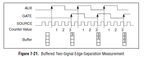
bad examples in two documents of signal edge separation
In the folder 'Two signals separation edge' examples are not two examples of signal.
They are two edge separation measurements made on a single signal.
I'm for any edges ofrising of separation between two signals Encoder on pairs of consecutive 1024 pulses. I couldn't find an example for this.
Is there something I could try?
Looks like you want something like this (Image of the M series user manual):
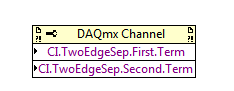
If you want to measure a finite number of impulses, you must use the 'soul two edge separation - Finite.vi buffered"is shown in the screenshot in your example finder. You must connect your two signals to the entries ' to the ' and 'GATE' of your meter. On many boards (for example, plugin M series), the default lines used are:
CTR 0:
To THE: PFI 10 (PIN 45)
PORTAL: PFI 9 (PIN 3)
CTR 1:
TO THE: PFI 11 (PIN 46)
PORTAL: PFI 4 (Paperback 41)
If you don't want to use the default values, you can edit the lines used with a channel property node DAQmx PFI:
The examples you linked measurement of separation edge on two different signals in the manner illustrated in the diagram above.
Best regards
-
[FlexRIO] Start-up to synchronize several clocks sample
Hello
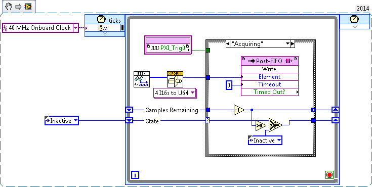
I tried before, two different (SMU-7962R + OR-5734) FlexRIO card reading in the '40 MHz Onboard Clock' or 'PXI_Clk10' areas of clock. Trigger has been achieved by simply looking for a rising edge on PXI_Trig0:
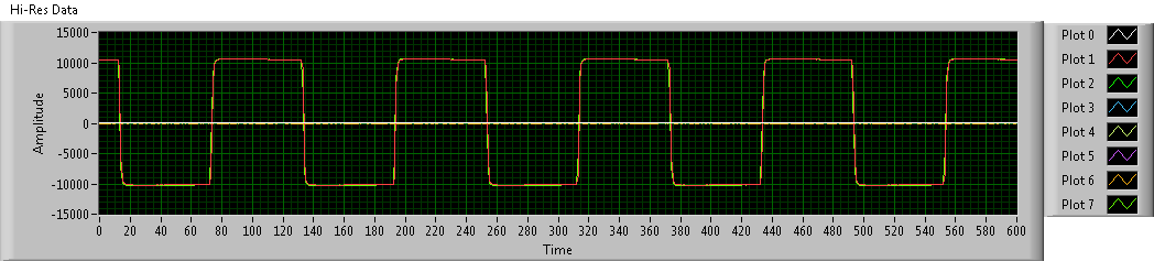
This produces seeds, but there has no inclination (or constantly tilt at least) between the two FlexRIOs - I sent a pulse train duplicated in the two cards, and the triggered-acquired waveforms were still at the stage:
To avoid problems, I went to examples of clock (IO Module clock 0). Unfortunately, the clocks of the sample between the two FlexRIOs had nothing in common, so the acquired waveforms have been is out of phase. Worse still, the phase difference changes with each release:
Looking at the implementation of the library of the synchronization of the FIDL, the classic technique for synchronization of multiple cards FlexRIO seems to be built around synchronization master-slave (my observation is correct?). I was wondering: is there a way to simply share a sample clock shared between cards (like what the 40 MHz embedded clock was doing before), as described in http://www.ni.com/white-paper/11369/en/ ? (I think I understand the disadvantages associated with sample clock synchronization, but I'm willing to try for now).
Thanks in advance!
Hi JKSH,
Page 9 of the Manual 5734 described the different synchronized methods that can be used the 5734. You can synchronize either sample clock of each module to a clock available through your chassis backplane (for example, DStar_A) by allowing the IOModSynClk in 5734 properties (available the Details category) or use an external clock through the Clk port on the module. Activation of IOModSyncClk is probably the best approach and will lead by examples of clock on each module e/s being PLLed on the clock of the town - which must synchronize the clocks of the two sample together.
Let me know if you have follow-up questions.
Kind regards
-
synchronize two cDAQ Chassis with DAQmx 9188
I try to sync analog entry tasks on two 9188 Chassis utilzing the build in the BNC (PFI 0 and 1) ports. I also have digital entry spots on the chassis of the master, I want to synchronize. Have been referencing http://www.ni.com/tutorial/5376/en/ and examples, I am not sure I have it set up correctly.
From the link above, I exported the SampleCLK to PFI0 and StartTrig to PFI1 on the chassis of the master. I have two BNC cables routed between ports on the two chassis. I put the trigger DAQmx start on the slave to the PFI1 source (this does not seem to do both tasks at the same time), I tried to adjust the pitch of the DAQmx (sample clock) of source PFI0, but it creates an error (requested sample clock source is not valid).
I can get the application of test runs by seting the slave clock "OnboardClock" sample source When I use this setting, the task two seem to start at the same time, but I don't think the slave chassis uses the master module sample clock and therefore might drift over time?
I would like to know how to properly synchronize the two analog tasks. I also want to synchronize digital tasks on the main frame with the analog task.
Hello
If you want to synchronize the two tasks, you share examples of clock and triggers via PFI lines. The only exception is that it is not currently possible to synchronize tasks between the chassis that use AI modules with delta-sigma a/d converters.
Best regards
Villanueva of the DSL.
-
Hello
I have a small question on an example of clock by RTSI source.
In my configuration, two PCI cards (PCI-6602 (dev2) and PCI-6110 (dev1)) are connected by a RTSI cable.
I would like to build a clock on 6110 source sample and use it on 6602 counting external impulses of entry.
In the MAX test Panel, I checked that a meter was reading of external signals.
However, the vi attached do not work, and the whole County, and then give an error of 200284.
Could you tell me what is the problem?
I guess that something is not right on the clock signal routing. I have to use DAXmx connect terminals vi instead of external signal?
How can I check that both devices are connected through a RTSI cable?
I recorded the cable and connected devices on MAX with no problems. Is this enough?
Thank you for your comments and kind suggesion.
Several things briefly:
- Must match the orientation of the RTSI cable. Connectors are generally indexed to ensure this, but if you use a cable in water House, just keep it flat between the boards.
- The code you posted attempts to use the time base internal 20 MHz as a sample clock. That will not work for several reasons, and the fact that you try suggests you may have a poor understanding of the functioning of the meter. You do * not * need to "sample" at a pace high in order to catch the digital transitions. The meter circuit manages everything in the material. What you "sample" in a task of counter is a County registry value. Digital TTL edges which are worth little matter how many times you "sample" it increases.
- I suspect you want to * account * cycles of the clock of the signal of your 6110, be it a train of pulses counter or a sample clock based on the tasks.
- I am writing an example that does without buffer sampling clocked by the software, to approximately 10 Hz. Dev2 uses to generate a pulse of 1000 Hz and uses Dev1 train to interrogate the County registry value in a loop. It is simple from the code you posted to help unravel the special problems of routing RTSI config problems. Start using something simple like this to see if DAQmx succeeds routing signals through RTSI.
-Kevin P
-
Clock and hw external trigger with USB-6210 on Linux with NOR-DAQmx Base?
I have two devices USB-6210 I need to synchronize so that they both collect data exactly at the same time. I was told by support OR I can send the clock off Dev1/PFI4 and have the two USB-6210 s read the clock in through their own PFI0. I also want to trigger data collected for each device by sending a trigger off Dev1/PFI6 and have two devices to receive the signal on PFI2.
All my attempts to try this are filled with error messages and my research online seem to say that's not possible with USB devices on NOR-DAQmx Base 3.4.0f2 on Linux.
I "ve tried using example AI programs and those who do not seem to work either for external clocks. Here is the code I tried:
#include "NIDAQmxBase.h"#include

#define DAQmxErrChk(functionCall) { if( DAQmxFailed(error=(functionCall)) ) { goto Error; } }

int main(void){    // Task parameters    int32       error = 0;    TaskHandle  taskHandle = 0;    char        errBuff[2048]={'\0'};    int32       i;

    // Channel parameters    char        chan[] = "Dev1/ai0";    float64     min = -10.0;    float64     max = 10.0;

    // Timing parameters    char        clockSource[] = "/Dev1/PFI7";    uInt64      samplesPerChan = 1000;    float64     sampleRate = 10000.0;

    // Data read parameters    #define     bufferSize (uInt32)1000    float64     data[bufferSize];    int32       pointsToRead = bufferSize;    int32       pointsRead;    float64     timeout = 10.0;

printf("Calling CreateTask...\n");    DAQmxErrChk (DAQmxBaseCreateTask("",&taskHandle));printf("Calling CreateAIVoltageChan...\n");    DAQmxErrChk (DAQmxBaseCreateAIVoltageChan(taskHandle,chan,"",DAQmx_Val_Cfg_Default,min,max,DAQmx_Val_Volts,NULL));printf("Calling CfgSampleClkTiming...\n");    DAQmxErrChk (DAQmxBaseCfgSampClkTiming(taskHandle,clockSource,sampleRate,DAQmx_Val_Rising,DAQmx_Val_FiniteSamps,samplesPerChan));printf("Calling StartTask...\n");    DAQmxErrChk (DAQmxBaseStartTask(taskHandle));printf("Calling ReadAnalogF64\n");    DAQmxErrChk (DAQmxBaseReadAnalogF64(taskHandle,pointsToRead,timeout,DAQmx_Val_GroupByChannel,data,bufferSize,&pointsRead,NULL));

    printf ("Acquired %d samples\n", pointsRead);

    // Just print out the first 10 points    for (i = 0; i < 10; ++i)        printf ("data[%d] = %f\n", i, data[i]);

Error:    if( DAQmxFailed(error) )        DAQmxBaseGetExtendedErrorInfo(errBuff,2048);    if(taskHandle != 0) {        DAQmxBaseStopTask (taskHandle);        DAQmxBaseClearTask (taskHandle);    }    if( DAQmxFailed(error) )       printf ("DAQmxBase Error %d: %s\n", error, errBuff);    return 0;}
When I run the resulting program, I see this:
$. / acquireNScans-ExtClk
The CreateTask call...
Call for CreateAIVoltageChan...
Call for CfgSampleClkTiming...
Error-89136 DAQmxBase:route specified cannot be satisfied, because the hardware does not support it. For example, a clock and a trigger can be imported via one of the PFI lines by using a USB-6210 on Linux with NOR-DAQmx Base? A clock and a trigger exportable via one of the PFI lines?
If so, does anyone have the code example illustrating how to do this, or can you at least tell me the names of the lines ("PFI0/Dev1" or other) so I can try again?
Clues or suggestions would be helpful.
Thank you
-Tom
The clockSource in the example specifies an output rather than an input channel channel. Change source "/ Dev1 / PFI0" solved the problem.
Please close this post.
-
Synchronization of two SMU 6537 in acquisition mode
Hello
I need to use two SMU 6537 in parallel for a digital acquisition, their examples of clock is synchronized and running at 50 MHz. In the manual, I can't know is possible to correctly route connections through PXI background:
-It seems that the path available only for export SAMPLING CLOCK in acquisition mode is 5 PFI, so no way to settle the two cards in a master-slave via the background.
-I don't see or can use the background 10 MHz REFERENCE for synchronization, because it seems impossible through the DAQmx driver to deliver this line as input for the time base and trigger (it is not even in the list of possible signal entries).
-The manual States that the maximum allowed value for an external time base is 50 MHz, whereas I need 50 MHz acquisition rate. I guess I should put in Sync synchronize databases internal time of the two councils through the background, but I can't figure out how.
Any suggestion on how to solve this problem?
Thank you, Piero.
Piero,
TO synchronize these cards, you must share the sample clock and a start trigger. You should be able to send the sample for PXI Trig 7 line clock and use it for each of them.
-Christina
-
He 'overflows' the screen about two inches around the perimeter. Example: The clock in the bottom right is almost invisible.
I don't need to change my resolution and cannot do with my monitor. Also, I don't speak of re-sizing the interface, not the wallpaper.What kills me is that I did this work before and he doesn't remember how!I have the latest drivers for my card AMD (helps nothing in the Catalyst Control Center) and the generic PnP monitor.How can I get instead of Windows 8 which allows me to adjust the size of the screen (no icon or text size and no resolution)? Am I crazy, or was it easy to find before?Thank you!Hello
This looks like a problem of scale .
Open the Catalyst Control Center.
Expand the section My Flat-Panel digital .
Select the item Properties (digital dish) .
In the resizing of the Image section, place a check in the option enable GPU scaling .
Select the image of the scale to the size of the full screen .
Click Apply/OK.
Test and let us know the results.
Concerning
-
Two clients to connect to a server?
Hi all
I want to develop applications for server and clients of more than one, how do I change the examples in the example of LabWindows/CVI 2013 finder,
Networking\TCP & UDP\
Server.CWS and client.cws?
I don't then do the programe kindly helps the two examples and me are committed
Concerning
Umer
Umer,
What you aren't able to edit? I could open both projects and change the code in each.
-
Simultaneous sampling using two cards PXI-6562
Hi all
I was wondering if it is possible to have two examples of cards PXI-6562 (e/s LVDS high flow) at the same time using the same trigger?
Thanks in advance,
Nathan
Hello
You can synchronize certainly several MSC devices, including modular instruments to NI HSDIO. The most effective way to proceed is to use the NOR-TClk synchronization API. It is provided with several of our drivers of modular instruments and devices, including NOR-HSDIO. The first part of this knowledge base explains the use of the NOR-TClk functions for that. This tutorial gives a very thorough introduction timing and synchronization using the API OR-TClk.
If you are more concerned with programming in fact such a request, I would check the NOR example Finder for some good examples. "" "" Navigate up to material input and output "modular instruments and devices" NOR-HSDIO "synchronization" to several features of dynamic Acquisition (TClk) .vi
Jon S
-
Clock at 10 MHz continues with 1.8 Vpp using 6544
Hi everyone, I need to have a continuous 10 MHz clock with the help of 8Vpp 1, NI6544. In the examples, I found these 3 examples for me:
1 dynamic generation with voltage Configuration.vi (example HSDIO)
2 dynamic generation with exported (example HSDIO) Clocks.vi
3 gen Dig Pulse Train-continues-Dig Start.vi (example Daqmx)
I have the NI6733 Council. But it wouldn't work with a frequency of 10 MHz. I don't know that it should be fairly simple to build. But I'm stuck right now.
Thank you, Yan.
I think I know what I'm supposed to do with the clock. It seems that I have to generate signals in DIO terminals or I need the signals digital or not.
How can the question, I get a single signal with just Boolean out 1 DIO. I mean, I want to have a controllable DIO with boolean regardless of the time. It's like I would have:
DIO0--> set to true, it gives me 1, 8V. If set to false, it gives me 0V. And it continues to run until it is manually stopped.
Thank you
Yan
-
DAQmx 50103 error, two tasks of MAX on the E-series
A bit of a surprise here, even after reading all the posts on the infamous error of-50103.
I'm debugging a data acquisition task, in LabWindows/CVI, for a PC with an E-series PCI card (PCI - 6032E, I think). There are two analog channels: one is a photoelectric sensor ("receiver") that is read in bursts, the other ('power') is an electricity meter that is read from time to time. I've set up two tasks, Max with the corresponding calendar and the trigger settings; Load them into my program using DAQmxLoadTask() and others, and we're off. Where I encountered problems, that's when I need to restart the task of 'Receiver' and re - allocate buffer according to certain parameters of execution. When I do that, the call to DAQmxStartTask() fails.
If, as I understand it, the problem is that you cannot have two tasks simultaneously running on the same tray, so why don't I get the error-50103 when I first start both tasks?
The basic sequence looks like this:
Init() //called once at the beginning of the init program the two tasks
DAQmxLoadTask (& Receiver_handle)
DAQmxSetTrigAttribute (& Receiver_handle)
AllocateBuffers()
DAQmxLoadTask (& Power_handle)
DAQmxSetTrigAttribute (& _handle Power)
AllocateBuffers()
InitTask(&handle) //called to stop and restart the task of the receiver with new buffer settings
CloseTask(&handle)
StopDAQ(&handle)
DAQmxStopTask(&handle)
DeallocateBuffers()
DAQmxClearTask(&handle)
DAQmxLoadTask(&handle)
DAQmxCFGInputBuffer(&handle)
DAQmxRegisterEveryNSamplesEvent(&handle) //register Manager of data (task receiver only)
AllocateBuffers(&handle)
StartDAQ(&handle) //called once for each task, called once again after the call to InitTask()
DAQmxStartTask(&handle) [failure]
The program successfully call StartDAQ twice at the beginning and starts each two tasks without error. I only get the - 50103 to the DAQmxStartTask () call the second time, I call StartDAQ() for the receiver, after the judgment task, reallocation of the buffers and reloading of the task (which happens without error). Any help much appreciated.
Hello
I hope that you had a wonderful holiday season, looking at your code, I think it will take to ensure that you have a task that is running, below I think would be the best way to initialize the task at hand and see if it works.
DAQmxErrChk (DAQmxCreateTask("",&taskHandle));
DAQmxErrChk (DAQmxCreateAIVoltageChan(taskHandle,"Dev1/ai0","",DAQmx_Val_Cfg_Default,-10.0,10.0,DAQmx_Val_Volts,NULL));
DAQmxErrChk (DAQmxCreateAIVoltageChan(taskHandle,"Dev1/ai1","",DAQmx_Val_Cfg_Default,-10.0,10.0,DAQmx_Val_Volts,NULL));
DAQmxErrChk (DAQmxCfgSampClkTiming(taskHandle,"",10000.0,DAQmx_Val_Rising,DAQmx_Val_ContSamps,1000));If this does not resolve your problems I check the example finder and see if any of this code is able to help you.
Finally, I have two examples of data strings at the same pace and if you have too many samples on a single line you can throw most of these samples.
I hope this helps,
Daniel -
This VI (ftp://ftp.ni.com/pub/devzone/epd/201150.vi) works exactly as I want to apply for a 8.6 at-, but the property node used in the example is no longer supported.
I can add/remove sites and resize the legend of the plot with 8.6 using the 'LegNumRows' property, but this property does not behave in the same way.
It seems like it should be simple, but I must be missing something.
Thank you to confirm that this property does not work in the same way as in the example when it is used with a XY graph clusters and no dynamic data.
I left the property node in the structure of the case (just as it was in the original example) while not to jam too when you went to compare two examples - my application does not for the reasons you stated.
I will implement a legend Manager to ensure the follow-up of the plots in the legend.
Thanks for the validation test!
Maybe you are looking for
-
Reset the emails received with more late on top
How to reset the emails received with more late on top
-
Satellite R630-13D: failed to create the recovery disk
I have a similar problem. I have a Satellite R630-13 t and tries to use the Toshiba recovery Media creator to create restoration 2 DVD discs. When you try to create the first disc, I get the following message: Cannot read the next file.E:\Boot\fonts\
-
OfficeJet 5740: New genuine cartridge does not work
I just bought a new ink a few hours there are the target. I played the installation video and proceeded to the installation of the new ink cartridge. Once I had finished the following pop-up came, "remove and install the specified cartridge, ensuring
-
some problems in vibe lenovo shot after update
Vibe Lenovo shot after update to 6.0.1 -When I open the VIDEO program opens file manager program. -The USIM toolkit does not -The battery was quickly released.
-
HP 5200 - print all of the pages that overlap on the first page
I'm having a problem with one of my users while trying to print on our 5200 s HP. This just started happening today and not affect any other users who also use printers. When the user prints a document of several pages, it prints all the pages on a s