Example of clock routing 'Terminal of Destination' = 'BoardClk? '
Several clock routing examples have a Terminal of Destination of "BoardClk". I can't find any documentation on what this is or where he's going. I've attached an example, "Route Clock.vi", which can also be found in example Finder > material input and output > timing and synchronization > Signal-based > road Clock.vi.
Specific material, with what I experience is the SMU-6674 t. I looked in the manuals for the SMU-6674 t and the SMU-1082 chassis. Google has no results.
Hello
Examples of NO-Sync include a number of modules. As a result, some of the terminals listed in the examples are not available on the SMU-6674 t.
BoardClk is only a valid terminal on the PXI-668 x modules. This terminal is used internally by the multi-device PXI_Clk10 software disciplining. With the PXI-6683 (H), this terminal can be used for single-device PXI_Clk10 discipline as well.
Kind regards
-Tyler
Tags: NI Software
Similar Questions
-
How to add two virtual channels with 2 examples of clock as different high sampling rates are required.
andy_kennaugh wrote:
Can we have several clocks sampling with different sampling rates high in a single VI?
What do you mean by "the sample clock? If you mean "sampling rate", of course, specific information. Personally, I like to be implemented in LabVIEW (New/task) project tasks, use to set the clock of origin, frequency of sampling, channels, sampling (e.g. in continuous) mode, Max/Min (e.g. ±10v), scale, etc.), and then wire a constant to the function of the virtual channels of DAQmx create, click on the arrow on the constant and choose the appropriate task (I have save as a mnemonic name such as 'Acquire the temperature').
Bob Schor
-
SOA deployment fails with 'connect; No router available at destination.
Hello
When I try to deploy my application soa on one my soadomain I get the following error. I am deploying through JDeveloper. I could successfully create a connection to the weblogic domain in which I deploy this application compsite. When I start the process of deployment through the JDeveloper IDE, it asks me to choose a server and when I walk through the wizard, it fails on the final step with the exception below.
It's Windows 7-64 bit machine. I use JDeveloper 11.1.1.5.0. My weblogic server is 10.3.5 and my SOA Suite 11.1.1.4.
java.lang.RuntimeException: javax.naming.CommunicationException [root exception is java.net.ConnectException: t3: / / * mymachinename *: 7001: Destination unreachable; nested exception is:]
java.net.ConnectException: Connection timed out: connect. No available at destination router]
Please advice...I believe that uses JDeveloper machinename to connect to the server.
so be sure that there is a DNS entry for it.
Add machinename to your hosts file could do the job.Also, make sure that no firewall rule prevents communication.
Also check that in JDeveloper, Tools/Preferences/Web Browser and Proxy does not point to a proxy server
And, of course, make sure that the server is actually in place and running and you can access the console using http://machinename:port / em.
and finally listen to your server address is empty (which is equivalent to accept any connection that resolves all IP configured for machinename)I might not be 100% correct, just trying to give you some advice...
-
Cannot replace the PXI embedded clock with clock oscillator PXI-6682 on PXI back plane
I installed a module of synchronization PXI-6682 to slot 2 of a PXI-1031chassis with a PXI-8110 controller running hypervisor and RT. The 6682 is installed on the RT system hypervisor for GPS sync during the measurements, but I would like to ask the TCXO on the PXI-1031 chassis backplane (which replaces the PXI embedded clock). When I try to run the "Clock.vi route" that I found in the finder of the example, all I get are error messages indicating that a parameter for this operation is not valid. The Terminal source is "Oscillator" and terminal of destination is "PXI-Clk10_In" How can I determine which parameter is not valid? Any suggestions? Thank you
Hi vugt.
You are right that the physical switch determines which one to use and you should not have to route signals. If you are having problems with clocks after the synchronization module 6682 please let us know!
-
synchronization and clock cDAQ-9174
I have a cDAQ-9174 with chassis
HAVE - 9205 OR 9205
HAVE - NOR 9219
DIO - OR 9401.
"NOR-DAQmx allows the on-board clock routing synchronize acquisition or generation of data transactions. A single sync signal or a trigger can be shared between multiple operations on the same device to ensure that the data are synchronized. These signals is shared by the simple signals routing functions that allow connections integrated hardware DAQ. " (from http://zone.ni.com/devzone/cda/tut/p/id/6829)
When I check the itineraries device in MAX tab' for chassis and c modules individually, I found many clocks with the Green blocks (direct Route). "Once a physical connection is determined, the NOR-DAQmx driver lets the user quickly and easily use this connection to synchronize operations".
Now my question is how do you choose among these clocks available. What is the frequency of these clocks? The highest frequency the better? What is the difference between /Ctr0SampleClock, /Ctr0InternalOutput, /Ctr0Source, /Ctr0A?
For example, why well/Dev1/I/SampleClock or Ctr0InternalOutput or of others, especially as a source for the .vi DAQmx Timing (sample clock)?
Thanks a lot for your help
Bing
Concerning
Hello NCLbingji,
I think you mix instructions from the manuals of different material. The link you posted refers to the synchronization of several separate devices, while your cDAQ with its modules really is like having one device almost. You will find more relevant information in your manual of cDAQ chassis. For multiple devices, you indeed have a "physical connection", but with the cDAQ is not necessary. You set up these connections in the software in any way, and this should get the routing sorting at the driver level.
Try to identify which channel will be your a 'primary', the one driving all others and synchronization, the value then asked SampleClock of this string as the rest (DAQmx Trigger.vi) trigger ('secondary') channels, then start all 'secondary' jobs and finally start your "primary" task This will trigger all tasks at the same time. Take a look at the attached picture, which is another application that I worked on, but I think this will help.
I hope this helps.
Kind regards
Michael S.
Technical sales engineer
NEITHER UK & Ireland -
Hello
I have a small question on an example of clock by RTSI source.
In my configuration, two PCI cards (PCI-6602 (dev2) and PCI-6110 (dev1)) are connected by a RTSI cable.
I would like to build a clock on 6110 source sample and use it on 6602 counting external impulses of entry.
In the MAX test Panel, I checked that a meter was reading of external signals.
However, the vi attached do not work, and the whole County, and then give an error of 200284.
Could you tell me what is the problem?
I guess that something is not right on the clock signal routing. I have to use DAXmx connect terminals vi instead of external signal?
How can I check that both devices are connected through a RTSI cable?
I recorded the cable and connected devices on MAX with no problems. Is this enough?
Thank you for your comments and kind suggesion.
Several things briefly:
- Must match the orientation of the RTSI cable. Connectors are generally indexed to ensure this, but if you use a cable in water House, just keep it flat between the boards.
- The code you posted attempts to use the time base internal 20 MHz as a sample clock. That will not work for several reasons, and the fact that you try suggests you may have a poor understanding of the functioning of the meter. You do * not * need to "sample" at a pace high in order to catch the digital transitions. The meter circuit manages everything in the material. What you "sample" in a task of counter is a County registry value. Digital TTL edges which are worth little matter how many times you "sample" it increases.
- I suspect you want to * account * cycles of the clock of the signal of your 6110, be it a train of pulses counter or a sample clock based on the tasks.
- I am writing an example that does without buffer sampling clocked by the software, to approximately 10 Hz. Dev2 uses to generate a pulse of 1000 Hz and uses Dev1 train to interrogate the County registry value in a loop. It is simple from the code you posted to help unravel the special problems of routing RTSI config problems. Start using something simple like this to see if DAQmx succeeds routing signals through RTSI.
-Kevin P
-
Clock and hw external trigger with USB-6210 on Linux with NOR-DAQmx Base?
I have two devices USB-6210 I need to synchronize so that they both collect data exactly at the same time. I was told by support OR I can send the clock off Dev1/PFI4 and have the two USB-6210 s read the clock in through their own PFI0. I also want to trigger data collected for each device by sending a trigger off Dev1/PFI6 and have two devices to receive the signal on PFI2.
All my attempts to try this are filled with error messages and my research online seem to say that's not possible with USB devices on NOR-DAQmx Base 3.4.0f2 on Linux.
I "ve tried using example AI programs and those who do not seem to work either for external clocks. Here is the code I tried:
#include "NIDAQmxBase.h"#include

#define DAQmxErrChk(functionCall) { if( DAQmxFailed(error=(functionCall)) ) { goto Error; } }

int main(void){    // Task parameters    int32       error = 0;    TaskHandle  taskHandle = 0;    char        errBuff[2048]={'\0'};    int32       i;

    // Channel parameters    char        chan[] = "Dev1/ai0";    float64     min = -10.0;    float64     max = 10.0;

    // Timing parameters    char        clockSource[] = "/Dev1/PFI7";    uInt64      samplesPerChan = 1000;    float64     sampleRate = 10000.0;

    // Data read parameters    #define     bufferSize (uInt32)1000    float64     data[bufferSize];    int32       pointsToRead = bufferSize;    int32       pointsRead;    float64     timeout = 10.0;

printf("Calling CreateTask...\n");    DAQmxErrChk (DAQmxBaseCreateTask("",&taskHandle));printf("Calling CreateAIVoltageChan...\n");    DAQmxErrChk (DAQmxBaseCreateAIVoltageChan(taskHandle,chan,"",DAQmx_Val_Cfg_Default,min,max,DAQmx_Val_Volts,NULL));printf("Calling CfgSampleClkTiming...\n");    DAQmxErrChk (DAQmxBaseCfgSampClkTiming(taskHandle,clockSource,sampleRate,DAQmx_Val_Rising,DAQmx_Val_FiniteSamps,samplesPerChan));printf("Calling StartTask...\n");    DAQmxErrChk (DAQmxBaseStartTask(taskHandle));printf("Calling ReadAnalogF64\n");    DAQmxErrChk (DAQmxBaseReadAnalogF64(taskHandle,pointsToRead,timeout,DAQmx_Val_GroupByChannel,data,bufferSize,&pointsRead,NULL));

    printf ("Acquired %d samples\n", pointsRead);

    // Just print out the first 10 points    for (i = 0; i < 10; ++i)        printf ("data[%d] = %f\n", i, data[i]);

Error:    if( DAQmxFailed(error) )        DAQmxBaseGetExtendedErrorInfo(errBuff,2048);    if(taskHandle != 0) {        DAQmxBaseStopTask (taskHandle);        DAQmxBaseClearTask (taskHandle);    }    if( DAQmxFailed(error) )       printf ("DAQmxBase Error %d: %s\n", error, errBuff);    return 0;}
When I run the resulting program, I see this:
$. / acquireNScans-ExtClk
The CreateTask call...
Call for CreateAIVoltageChan...
Call for CfgSampleClkTiming...
Error-89136 DAQmxBase:route specified cannot be satisfied, because the hardware does not support it. For example, a clock and a trigger can be imported via one of the PFI lines by using a USB-6210 on Linux with NOR-DAQmx Base? A clock and a trigger exportable via one of the PFI lines?
If so, does anyone have the code example illustrating how to do this, or can you at least tell me the names of the lines ("PFI0/Dev1" or other) so I can try again?
Clues or suggestions would be helpful.
Thank you
-Tom
The clockSource in the example specifies an output rather than an input channel channel. Change source "/ Dev1 / PFI0" solved the problem.
Please close this post.
-
SG500X battery strange printer HP routing
I have a weird problem with 2 HP LaserJet 400 printers in the series (only 2 of these series on the network,) but more than 20 other printers to work and many other features, they are also well connected on a set of switches of SG500X and static IP value with firewalls as the default gateway, because it manages all of our connections to routing and WAN.
Printers work fine locally, but most of the time will not communicate across the Wan, when I restart each printer is available on the Wan for a few minutes, then without answers ping or connectivity of any kind.
Then... I have mirrored from the port of one of the printers on my desktop, have fired up Wireshark and found that when the printer responds to the ping command with the remote subnet that responds to switch to the printer with "Destination unreachable" so I created a route in the switch for the remote subnet to the internal interface on our firewall , and it seems to work fine now, but I can't understand why I needed to do in the first place, given that printers should use the firewall as a default gateway.
Any ideas? Thanks in advance
Hi Steve, it seems fair that something is not respected on the configuration. How interpret your post, your switch is used in a mode of layer 2 and intervlan all requests are routed through the firewall.
If the switch is used in mode layer 3 but your firewall is routing inter - vlan, it would be a configuration such as additional roads may be required for basic functionality. Any time you have a SVI on a layer 3 switch that a route must be done on the router upstream unless it knows how to send the subnet traffic by other means.
All the messages are indeed weird to me.
Let's take an example your interface routed is 10.1.1.1 and your printer is 10.1.1.2. If the switch is in layer 2, the INVESTIGATION period won't matter. If the switch is on layer 3, it should have something like 10.1.1.254 an SVI. For layer 3, the bridge of the printer must be the SVI to the switch.
It should work a feature of base layer 3, described the two scenarios.
-Tom
Please mark replied messages useful -
remote router configuration with EzVPN NEM by VPN
I have the following scenario: Some 836 routers Cisco EzVPN network are connected to a hub VPN 3005 in the main façade.
The work of LAN-to-LAN connection and I can also telnet via the VPN from a PC to the main façade of a router to a remote site using the address LAN IP of the remote router as a destination. But does not work for example do a "copy run tftp" on the remote router to the LAN of the main façade.
My questions now are:
Is it possible to transfer the remote routers configuration file or via the VPN IOS image between the remote router and the LAN at the main façade?
And, if possible, how do we?
Thanks in advance
Mark
When you make a "copy run tftp" from the remote router, it goes to the source of its external interface TFTP packets, not its interior. The external interface to your local network packets are NOT included in the list of packages to be encrypted, and therefore they lose.
You must specify the router to the source its TFTP packets from the interface IP address inside, then these will be correctly encrypted and sent through the tunnel.
The following command should do the trick for you:
IP tftp source-interface
-
Hello
If someone could explain the differences between content, routing function, context based routing and dynamic routing
Thank you
Barros.Hi Baro,
Content based routing - content-based routing is intended to route messages, not by a specified destination, but by the actual content of the message itself. In a typical application, a message is routed by opening upwards and by applying a set of rules for its content in order to determine the parties interested in its content.
Context based routing - routing based on the source of the message (for example, IP)
Dynamic routing - in dynamic routing, a message is analyzed by using controls conditional in the statements of conditional branches, to retrieve the value of a data element or multiple data elements that determine the routing logic. Destinations service different cases are assigned to the different crossings as a result of this conditional control. The message is dynamically routed to one of multiple business services destination based on the value of the data item. Transformations can be applied to the response message goes to one or more of these destinations according to the needs of business.
Kind regards
Anuj -
How this error is possible with the simple example of EJB model?
javax.naming.CommunicationException [root exception is java.net.ConnectException: t3://127.0.0.1:7101: Destination unreachable; nested exception is:]
java.net.ConnectException: connection refused. No available at destination router]
at weblogic.jndi.internal.ExceptionTranslator.toNamingException(ExceptionTranslator.java:40)
at weblogic.jndi.WLInitialContextFactoryDelegate.toNamingException(WLInitialContextFactoryDelegate.java:783)
at weblogic.jndi.WLInitialContextFactoryDelegate.getInitialContext(WLInitialContextFactoryDelegate.java:367)
at weblogic.jndi.Environment.getContext(Environment.java:315)
at weblogic.jndi.Environment.getContext(Environment.java:285)
at weblogic.jndi.WLInitialContextFactory.getInitialContext(WLInitialContextFactory.java:117)
at javax.naming.spi.NamingManager.getInitialContext(NamingManager.java:667)
at javax.naming.InitialContext.getDefaultInitCtx(InitialContext.java:288)
at javax.naming.InitialContext.init(InitialContext.java:223)
to javax.naming.InitialContext. < init > (InitialContext.java:197)
at test.client.SessionEJBRemoteClient.getInitialContext(SessionEJBRemoteClient.java:259)
at test.client.SessionEJBRemoteClient.main(SessionEJBRemoteClient.java:34)
Caused by: java.net.ConnectException: t3://127.0.0.1:7101: Destination unreachable; nested exception is:
java.net.ConnectException: connection refused. No router available at destination
at weblogic.rjvm.RJVMFinder.findOrCreateInternal(RJVMFinder.java:216)
at weblogic.rjvm.RJVMFinder.findOrCreate(RJVMFinder.java:170)
at weblogic.rjvm.ServerURL.findOrCreateRJVM(ServerURL.java:153)
at weblogic.jndi.WLInitialContextFactoryDelegate.getInitialContext(WLInitialContextFactoryDelegate.java:352)
... 9 more
Caused by: java.rmi.ConnectException: Destination unreachable; nested exception is:
java.net.ConnectException: connection refused. No router available at destination
at weblogic.rjvm.ConnectionManager.bootstrap(ConnectionManager.java:464)
at weblogic.rjvm.ConnectionManager.bootstrap(ConnectionManager.java:315)
at weblogic.rjvm.RJVMManager.findOrCreateRemoteInternal(RJVMManager.java:251)
at weblogic.rjvm.RJVMManager.findOrCreate(RJVMManager.java:194)
at weblogic.rjvm.RJVMFinder.findOrCreateRemoteServer(RJVMFinder.java:238)
at weblogic.rjvm.RJVMFinder.findOrCreateInternal(RJVMFinder.java:200)
... 12 more
Process has finished with exit code 0.
------------------------------
can someone guide me on the resolution of this error? I do this oracle example:
http://www.Oracle.com/technology/OBE/obe11jdev/ps1/EJB/EJB.html
Thank you
VaelYou must add the MySQL library on the integrated WebLogic Server.
See last step here:
http://jobinesh.blogspot.com/2009/06/ADF-with-MySQL.html -
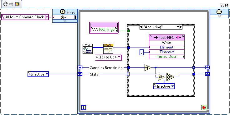
[FlexRIO] Start-up to synchronize several clocks sample
Hello
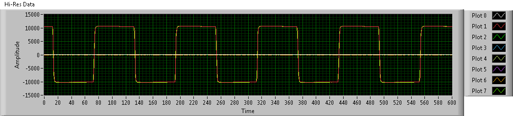
I tried before, two different (SMU-7962R + OR-5734) FlexRIO card reading in the '40 MHz Onboard Clock' or 'PXI_Clk10' areas of clock. Trigger has been achieved by simply looking for a rising edge on PXI_Trig0:
This produces seeds, but there has no inclination (or constantly tilt at least) between the two FlexRIOs - I sent a pulse train duplicated in the two cards, and the triggered-acquired waveforms were still at the stage:
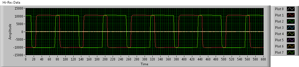
To avoid problems, I went to examples of clock (IO Module clock 0). Unfortunately, the clocks of the sample between the two FlexRIOs had nothing in common, so the acquired waveforms have been is out of phase. Worse still, the phase difference changes with each release:
Looking at the implementation of the library of the synchronization of the FIDL, the classic technique for synchronization of multiple cards FlexRIO seems to be built around synchronization master-slave (my observation is correct?). I was wondering: is there a way to simply share a sample clock shared between cards (like what the 40 MHz embedded clock was doing before), as described in http://www.ni.com/white-paper/11369/en/ ? (I think I understand the disadvantages associated with sample clock synchronization, but I'm willing to try for now).
Thanks in advance!
Hi JKSH,
Page 9 of the Manual 5734 described the different synchronized methods that can be used the 5734. You can synchronize either sample clock of each module to a clock available through your chassis backplane (for example, DStar_A) by allowing the IOModSynClk in 5734 properties (available the Details category) or use an external clock through the Clk port on the module. Activation of IOModSyncClk is probably the best approach and will lead by examples of clock on each module e/s being PLLed on the clock of the town - which must synchronize the clocks of the two sample together.
Let me know if you have follow-up questions.
Kind regards
-
problem reading DAQmx using Measurement Studio 2010 (even with examples OR)
Hi all
I'm reading the voltage using a map of NOR-DAQ-6211 with Measurement Studio 2010 SP1 V9.1.0.204. using Visual Basic .net 2010.
When I create the task of data acquisition with the measurement studio Wizard, (Assistant DAQ) everything works fine. However, when I try to create my own task player in looking over the "ContAcqVoltageSamples_IntClk" everything I read is a value in the range of Vmin to Vmax (or to Vmin Vmax) and then she stays there no matter if I change my diet. Vmin and Vmax does not yet match my values of voltage. (It acts like that on my application and example of OR) I guess I missed a few initial settings. The config of AIChannel in two projects (manual task and Augo-Gen) use AIChannelConfig.RSE (I tried other options, but no luck).The only wiered thing is that when I open examples of projects, VS does not recognize the object references of NOR. Workspace names DAQmx. When I check the references, it shows that it does not find the reference to NI.Common. To make it work/compilation, removed from the solution and I again added. (I don't think this is related, as it seems that there are available tensions but not read correctly).
The other thing is that my input voltage is 3 or 0 volt. When you use the manual DAQtask, when I toggle the voltage, the values displayed change momentarily the order of 0.001 Volts and then go back to their previous values of Vmax and Vmin.
Is there more information I can provide?
Help, please
Thank youYay! I just solved my problem,
From the first moment I knew there was something fishy about this AITerminalConfig thingy! I made two errors:
1. in the code example Configuration AI is encoded: CType (-1, AITerminalConfiguration) that caused the code example does not work for all channels to HAVE it
2 - also, I have in my code, I had put this config to the correct value, but I was checking ai0 all the time while the signal was on another I. I was under the impression that since the example does not work for all my channels, then probably my code does not work as well.
If after changing the line in the example for the correct terminal configuration settings, he began working for the AI number I was looking for too much and I found that my code worked for my AI # correctly from the beginning. I wasn't just to see it!
-
Clock at 10 MHz continues with 1.8 Vpp using 6544
Hi everyone, I need to have a continuous 10 MHz clock with the help of 8Vpp 1, NI6544. In the examples, I found these 3 examples for me:
1 dynamic generation with voltage Configuration.vi (example HSDIO)
2 dynamic generation with exported (example HSDIO) Clocks.vi
3 gen Dig Pulse Train-continues-Dig Start.vi (example Daqmx)
I have the NI6733 Council. But it wouldn't work with a frequency of 10 MHz. I don't know that it should be fairly simple to build. But I'm stuck right now.
Thank you, Yan.
I think I know what I'm supposed to do with the clock. It seems that I have to generate signals in DIO terminals or I need the signals digital or not.
How can the question, I get a single signal with just Boolean out 1 DIO. I mean, I want to have a controllable DIO with boolean regardless of the time. It's like I would have:
DIO0--> set to true, it gives me 1, 8V. If set to false, it gives me 0V. And it continues to run until it is manually stopped.
Thank you
Yan
-
672PCI 6723 error when you try to generate a signal with the sample of 20 kHz clock
I have a piece of code that worked successfully on the PCI-6224 map, but when I tried to implement the same code on the card PCI-6723 I ran into problems.
Here is the code I use:
ManchConversion6723();//produces SendIt array of series of 1s/0s

// DAQmx Configure Clock
DAQmxErrChk (DAQmxCreateTask("",&taskHandleFRQ));
DAQmxErrChk (DAQmxCreateCOPulseChanFreq(taskHandleFRQ,"Dev3/ctr0","",DAQmx_Val_Hz,DAQmx_Val_Low,0,20000,0.5));
DAQmxErrChk (DAQmxCfgImplicitTiming(taskHandleFRQ,DAQmx_Val_ContSamps,72));

// DAQmx Configure Digital Output
DAQmxErrChk (DAQmxCreateTask("",&taskHandle));MessageBox("D");//vj
DAQmxErrChk (DAQmxCreateDOChan(taskHandle,"Dev3/port0/line0","",DAQmx_Val_ChanPerLine));MessageBox("E");//vj
DAQmxErrChk (DAQmxCfgSampClkTiming(taskHandle,"/Dev3/Ctr0InternalOutput",20000,DAQmx_Val_Rising,DAQmx_Val_ContSamps,72));

// DAQmx Write Code
DAQmxErrChk (DAQmxWriteDigitalLines(taskHandle,72,0,10.0,DAQmx_Val_GroupByChannel,SendIt6723,NULL,NULL));

// DAQmx Start Code
DAQmxErrChk (DAQmxStartTask(taskHandleFRQ));
DAQmxErrChk (DAQmxStartTask(taskHandle));
When I get on the DAQmxCfgSampClkTiming line, I get an error stating:
DAQmx error: measurements: request the value is not supported for this property value.
Property
 AQmx_SampTimingType
You asked: DAQmx_Val_SampClk
You can select: DAQmx_Val_OnDemand
Task name: _unnamedTask<0>
State code:-200077
I think that the problem comes from the variable of the source of the function. I'm just tring to send the data to the frequency of 20 kHz.
Any help would be greatly appreciated. Thanks in advance!
Too bad. The impression that the PCI-6723 does not contain correlated DIO channels. In other words, examples of clock cannot be linked to the DIO channels allowing the generation of digital waveforms. According to the AO Series user manual, this applies to the NI 6731/6733 only. The mistake was trying to tell me that only a single issue or receive channel has been authorized.
For this reason, I'll stick right with my card PCI-6224.
Sorry for the confusion.
Maybe you are looking for
-
Why me charged 3 times for Garageband?
I recently bought garageband (the app, no in-app purchases) using my debit card and I was charged 3 times for her. I don't know about the payment of test they do on your account. Why what happened? Is there a way to see the transactions that I did? I
-
I got a new computer (an old dies) new a windows vista and I have to disable the old computer before I load the same copy of Vista on my new computer. If yes how can I do this?
-
Vista Bluescreen BCCode 116, pls help!
Signature of the problem: Problem event name: BlueScreen OS version: 6.0.6002.2.2.0.256.6 Locale ID: 1033 More information about the problem: BCCode: 116 BCP1:
-
Not available in Eclipse Java.io.FileReader?
http://www.BlackBerry.com/developers/docs/5.0.0api/Java/IO/FileReader.html I am trying to impliment a XML parser, however, this FileReader library is not available for import. I read on another thread that it was not allowed. But then I read the lin
-
Hello I am a user of Windows 7 and I've been experiencing problems with the closing in recent times. When I try to shut down my computer, the icons in the taskbar and desktop disappear as they usually do, but the screen freezes, showing only my deskt