txt to the waveform table
Hello!
Just a simple question: I have a txt file with the following structure:
2012.03.13 19:13 6.93E - 05
2012.03.13 19:14 6.29E - 05
2012.03.13 19:15 5.66E - 05
2012.03.13 19:16 5.21E - 05
. ..
Then delimited by tabs of the values and timestamps.
I want to send them to a waveform graph. Can someone show me "elegant" way to do this, I think I could do it in a very ugly way...?
Samples of data attached and my VI that I wrote so far...
Thanks in advance,
You were very close. I have attached your VI with the analysis of the timestamp. You can find the timestamp format codes in aid of LabVIEW in the Codes of the time Format String Format.
Note that I used only the first two timestamps, assuming that the data has been evenly spaced. You could also use an XY graph and use all the timestamps, if you want. In addition, to get the timestamps to appear on the graph, you must right-click on the chart and clear the option ignore timestamp.
Tags: NI Software
Similar Questions
-
How to set the waveform table to start data since the beginning of the race
Create a property of the graph node. The property you are looking for is history. This property, you can clear the table.
-
How to make the waveform table rows less laeti WITHOUT using a lot of mathematics of interpolation
So I use a graph shaped wave, the numbers of entries sequence like that, sensor 22,23,24,25... the graph seems laeti. (Fussy) client says hey I want a good graph, you have function spline or something?
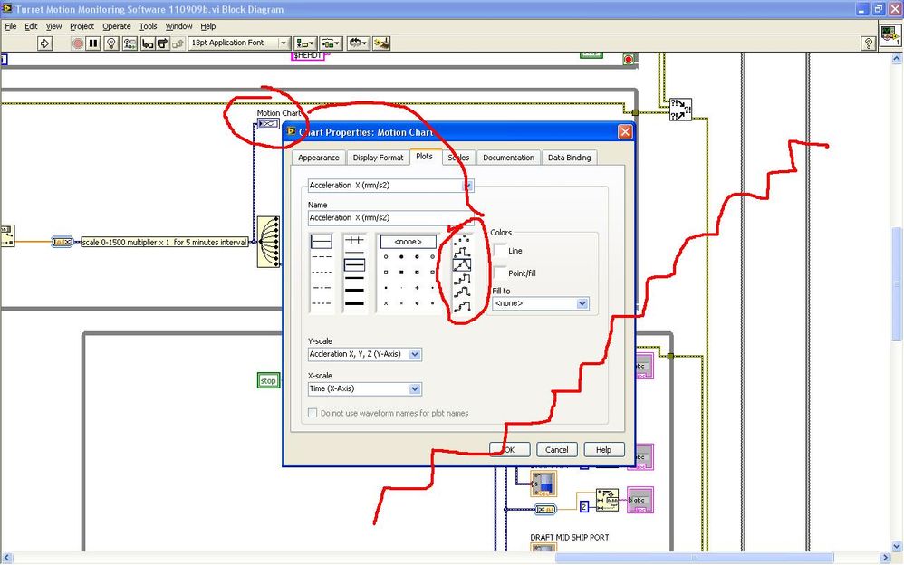
So I was to research the properties of chart and saw the settings below that does not help much. I proposed to the customer (picky) that Hey maybe we can make the balance Y greater for the lines of the stairs will be not so obvious, the customer (picky) says no. So I was sweating on tedious mathematics required for interpolation in the hot oil and noisy, without internet, fortunately the dinner bell rang.

Now is there some function blocks which makes the table lines smooter, a function spline or something? Thank you.
-
How display the waveform acquired DAQ card separately in wavefrom graphic
I NI 9239 DAQ card and it has four channels. I need to create a user interface graphic labview in which I need to display all the forms of four wave separately. If I select all four channels of the daq assistant and connect the waveform table all four waves are coming to overlap... I need separately for the treatment... what should I do?
Thank you and best regards...
Try this
-
Reference to the waveform diagram
Hello world!
Im having some problems with my code. I can't put a reference line (or another function, as a sinusoid of reference) in the waveform table, I tried to put a package but I couldn't make it work, the wire bundle not on the list of waveform. I would like the references to stay still and moves not as pictured.
the other thing is that im working with control of the force, and I want to record in a table of max 3 force values (there will be 3 tasks of the maximum force, and I want to save the 3 max values with 60 s interval between them, by running the program only once), but it does not work.
some ideas, please?

To write more than one location in your chart, you need an array of waveforms. A waveform will be your reference. You can make one for each of your values of max.
-
Capture of waveform in the waveform diagram
Hello
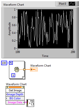
I am trying to capture the waveform in the waveform table save it as an image.
The reason why I'm not backup data is that we have a lot of test data and we do not want to draw hundreds of waveforms again manually.
No one knows how to do?
Thank you!
Here's an easy way to save an image of the graph.
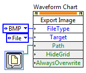
You can save only the graph as BMP, EPS, EMF, or PICT with another method:
-
missing scenario of the external table file
Hi What is happening...
When we access the external table, and the file is not present... it throws an error? It simply returns the rows null?
If I know I will get 5 files a.txt b.txt, c.txt, d.txt, .txt, and then I can put in the location
LOCATION ('a.txt ',' b.txt ',' c.txt ',' d.txt', ' e.txt") creating the external table
If for example b.txt and c.txt are not present at the time of access, it will throw an error or it just shows me the records of a, d and e?
concerning
REDARaj,
If you have missing files, you select will return an error. So make sure that file, even if its empty.
You will see the following error
CREATE TABLE ext_tab (
   empno CHAR (4),
   ename CHAR (20),
   job CHAR (20),
   deptno CHAR (2)
)
ORGANIZATION EXTERNAL
   ( TYPE oracle_loader DEFAULT DIRECTORY EXPORT_DIR ACCESS PARAMETERS (
   RECORDS DELIMITED BY NEWLINE BADFILE 'bad_%a_%p.bad' LOGFILE
   'log_%a_%p.log' FIELDS TERMINATED BY ',' MISSING FIELD VALUES ARE NULL
   REJECT ROWS WITH ALL NULL FIELDS ( empno  ,
   ename ,
   job   ,
   deptno) ) LOCATION ( 'emp.dat','emp.dat1' ) );

select * from ext_tab;

ORA-29913: error in executing ODCIEXTTABLEOPEN callout
ORA-29400: data cartridge error
KUP-04040: file emp.dat1 in EXPORT_DIR not found --> emp.dat1 doesn't exist but emp.dat exists
ORA-06512: at "SYS.ORACLE_LOADER", line 19
Concerning
-
How can I set the time axis on my waveform table to show run time that is to say whenever I start the program I should have 0 as the starting point. I've been messing around with the without success. I'm under Labview 2012.
Thank you!
Townes wrote:
I can't understand what you mean. I have no formal training with labview. It took me a long time to write the simple program that I joined. Any guidance would be greatly appreciated!
Its pretty normal for a beginner to take the time to write code. Right-click the map of waveform > Create > property node > historical data, you will get a property node, keep this at the beginning of the code and create a constant. You can also go to the VI properties and > run and select "clear indicators when it is called.
I recommend you to go through the basic materials of LabVIEW which will give you an understanding on the basics of bases/components of LabVIEW.
-
Control the properties of the graph of a waveform for waveform table.
I'm to customize a waveform graph. I will have no problem using nodes property to define all the things I need to (color plot, the names of axes, etc...). My wave form is actually an array that contains the seven waveforms. The problem is that the property of the waveform graph node changes only trace, legend, etc. the first signal in the graph. They all have the chart perfectly together. However, my application requires the user to be able to select say signals 2, 5 and 7 of the table. When it does, it receives signals of 2, 5 and 7 on the chart, but the legend Watch reports 1, 2 and 3 and they draw in the colours of the signals 1, 2 and 3. Any suggestions on the update of the properties of several plots of a waveform graph?
Also when I want 1 signal trace a curve of waveform. When I want the signals from 2 to 7, I have to draw a second copy of the curve of waveform. For some reason any a waveform table chart cannot double as a unique waveform graph. Any ideas on that? Thanks in advance for your help.
To change the properties of other signals in the chart, you will need to set the ActivePlot property node before writing the color, the name of legend, etc... To display only the selected signals, you could do a couple different things.
(1) set the color of the signals that are not visible by transparency
(2) write NaN values to the curve of waveform of the signal that you do not want to display
-
Waveform table do not see the time correctly
Hello
I am trying to represent the time vs. keithley multimeter voltage using a waveform chart. The voltage is recorded properly, however, the time does not seem to match. It shows approximately 10 times higher seconds. See the attached VI where I also used alternatively a XY Chart. I would like the time to be displayed in the waveform graph as in this chart XY.
In addition, in the XY graph, I had to put up one zero time to obtain the relative time. Is there a simpler way to do rather than use this trick?
Thank you.
-
Why my sample rate does not match the output of timestamps in the waveform?
Hello
I run a simple application to read the data of two pressure sensors output signals 0 - 5V to a NI9215 module, and one connected to the 9237 module load cell. They are housed in the 9172 chassis.
I am new to DAQ and labview, and I find it difficult to reconcile the sampling frequency that I put in the sample clock and the apparent rate data (according to the timestamps in the waveform that I output to a text file). For example, if I ask 100 Hz rate (and 10 samples to read), the data appear to sample at 1612,9 Hz. If I ask the sampling frequency of 1000 Hz, outgoing data is 1612,9 Hz to 20 kHz, the data came out to 25 kHz.
Can someone tell me to trust the timestamps given in the waveform that is written in the text file, and if there is a way to check this? If this timestamp is correct, how can I force the application of sample data at the requested speed?
As a secondary issue, in my attached VI, you can see that I have an attached to an array of construction shift register. I can't understand how to initialize the array outside of the loop as it clears the table before the next time I run the program. Any advice?
My VI is attached.
Thank you
Claire.
Hi Marc, thanks for the quick response and the right explanation. It's all much more clear now.
Have a great weekend,
Claire.
-
missing samples in the waveform graph
Hello world
When processing a file .wav into pieces, I noticed that there are missing samples on the waveform graph where two pieces must be met for the display. What could be the cause of this? Any help appreciated. Thank you!
Milan
Your method of reading in pieces in a for loop is create a table 1 d of waveforms with the tunnels of automatic indexation. It is as well as what you have the data appear in different plots. I don't know if that's what you want.
But if this is the case, the problem is that you get to the last point of the first plot, and the first point of the next parcel is a different value. Because they are two different plots that you do not get the line to join them, as you do between points that are part of the same plot.
-
Control of data using multiple thermocouples via indicators and the waveform in real-time
I apologize in advance for this question is probably a bit simple but I'm all new to labview and the forum and could use some advice. I have a CompaqDAQ with two 9213 16 modules of track and I'm trying to read in 30 thermocouples in a waveform, but also display 30 indicators so I can mark each indicator with the thermocouple for real-time tracking. Each thermocouple corresponds to a specific location and it is essential that the interface has an accurate indication or a label for each of them. I wonder if there is an easy way to do this in addition to split the signal and have 30 thermometers on my diagram? Perhaps a table any? If I use a table to create 30 thermometers, the DAQ assistant automatically sorts the thermocouples according to ascending numerical order. For example, would be the indicators of first and second on my interface automatically assigned to channels a0 and a1 of the first module, or should I do it manually? Even for the waveform? Thank you very much!
PS - Do not know if this message had need of more details, but let me know if more information is needed, and I'll give you!
I see that you use the DAQ Assistant to create your task. Now I understand why you may have about labelling. It is easy of the seller NOR spiel booting... But in any case, you already have a task to the MAX instead of use the DAQ Assistant? The interface is similar and there may be a step or two, but your end application will be more effective and you will have more options with your data and properties. For example, I tried to update the names of physical channel in the DAQ Assistant installation program, that it let you do, but it propagates that change forward to waveform chart legend. Also, I don't know any property for this dynamic data type node, although I never use it either. I suggest the setting up of your task and channels, Max if you'd give it a go.
Since I thought I didn't really takes you all the way with you help, I wrote another one. It uses a cluster, even if it's a bit barbaric. I thought that there was a more eloquent way to do by changing labels, but I could not it works as I had expected.
-
How to rebuild the waveform with zero new and create histogram type of waveform?
Hello everyone, I have an application where I need to rebuild a waveform using some amount of 'x' of the data samples. the conditions are:
1. the new zero of the new waveform is peak value frm the old form of wave., allows to assign this value of y s.
2. based on this peak value, I have to draw points of sampling (y - t) and (y + t)...
the waveform above may look like a histogram, but isn't exactly a histogram... can anyone suggest a concept?
I'm not able to take the time to "throw in a sample VI.
But if you look at the help file get the subset of waveform, you will see that he has all the inputs you need.
There is an enum constant that allows you to choose samples or time. I would say that the samples since this is what will come from most of the table Max/Min detector or Peak live
There is a sample start time. Put in the value of your Ridge detector less t.
There was a time. Put in the value of t 2 times.
If t is the time, you may need to convert to samples based on your sample rate.
-
Make a different .txt 3 1 d-table file
Community salvation OR
I looked a decent solution for this problem, but I can't understand how do.
So I have a Subvi, which calculates the different images 3D coordinates. Each image contains about 200 points which will be calculated. The output of the Sub - VI are 1 d 3-tables, one for each dimension. I want to make a .txt file where the coordinates are written as follows:
x 1; Y1; Z1
x 2; Y2; Z2
x 3; Y3; Z3
...; ...; ...
XN; Yn; Zn
The coordinates of each image entering the VI calculation should be added in this .txt file regarding the described structure.
Is there anyone who got experience with this and know a good solution? If something is not clear to you, please ask me to explain.
Kind regards
Ruts
I don't know how your photo in the upper part compares with what you did until now.
You can combine several tables 1 d without knowing how they are. You put the version table in a loop For. Maintain the 2D range in a shift register and add each new table 1 d with the table to build inside the loop For.
Maybe you are looking for
-
Someone know if 10.11.3 corrects mail problems or makes it worse?
As any search for "El Capitan mail problems" reveals, there are myriads of problems with the original "up" grade, which have not been resolved in versions 11.1 and 11.2. Before I go through another update, can we say if ONE of these problems (breaks
-
Hi all Just brought an iPod classic 30 GB with only the USB charge lead. Will be using the USB cable and the 5 Watt Mini iPad adapter for my iPod? See you soon
-
y700 - good custom presets for Audio advanced Dolby?
Dolby advanced audio software. someone at - he of the good custom presets? I looked everywhere for some Mod edit: additional information added to the subject for the clarity of the question line.
-
How can I reset my password without password reboot disc or flash drive?
OT: I forgot my login. How can I reset my password without password reboot disk or flash drive. I screen login password, but it won't let me connect
-
Bitmap.getBitmapResource (...) does not find my file?
Hi all, I'm a 1st year student at the University of Warwick (United Kingdom) and I'm writing a small application for the Blackberry Storm, but I can't get my code to use just... Bitmap image = Bitmap.getBitmapResource ("c.gif"); BitmapField bField =