USB 6008 pull down resistance
Hello
I have a USB-6008 read a signal to 5V on one of DIO ports. The 5V is or the circuit is open. Since the 6008 traction has internal open ups resembles a true TTL signal. I think using a 850 Ohm pull down on the output line. I think that should lose about 5.8ma when the 5V is present. 6008 for line specification is 8.5ma. The 5V is coming from a mechanical switch which is activated when the vacuum is applied, so that the switch does not consume all current... It seems to me that it should work. But............ Does anyone see a problem with that?
Thank you
Alan
Connect the switch to the Gnd and reverse the bool off the DAQmx Read?
Tags: NI Software
Similar Questions
-
I have a USB-6008, I read an entry on the OID.
I want this 1 report when the line has a present 5v and 0 for something else.
When I don't have anything on the lines. It reads 1
How configure it to read 0 when nothing is connected?
Also how I re this in c#
Thank you
Hello ashitakaLax,
The USB-6008 housing has an internal pull-up resistance to 5V (according to page 22 of the User Guide and specifications) that pulls the line to 5V when nothing is connected.
In order to change this, you can add an external resistance of menu drop down to make the output to the earth when it is disconnected, if your device should get power to fuel the high line.
Kind regards
-
LabVIEW think my NI USB-6008 has only analog inputs
I am using an NI USB-6008 box to run a route of analog input and analog output.
If I do a constant material DAQmx channel and out the finger tool and pull down... and it offers me 8 analog inputs on Dev1 and nothing else. I've nothing else connected to this computer, but the box USB-6008. A USB-6008 doesn't even have 8 analog input channels.
I'm a bit confused.
-
Input/output USB 6008 test failure
OK I am posting this for the third time, but whenever I go back to the home page of the forum, I'm not able to find my post. If by chance I created duplicates than apologies.
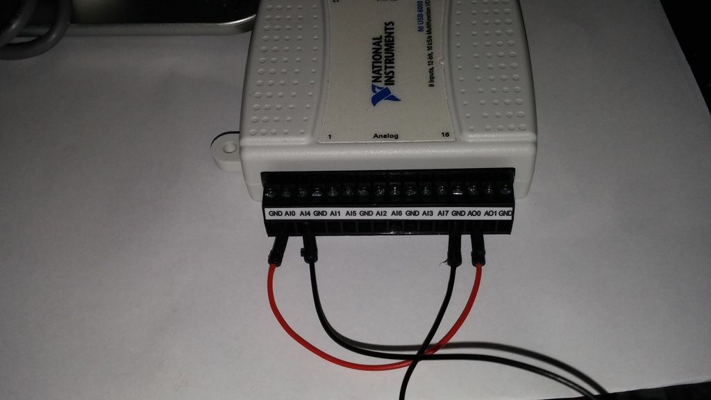
IAM in train to test the USB-6008 case I just got and decided to hang the analog of the analog inputs and see using labview VI.the wiring was done as:
http://i284.Photobucket.com/albums/ll5/bigdawg6/USB%206008%20wiring_zpss2b7hql9.jpg
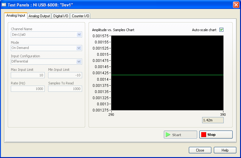
the problem is that the labview VI did nothing, so I go to NI Max and try to see in test panels. But I get 1.4V constantly my same analog input value when I'm changing my analog value:
http://i284.Photobucket.com/albums/ll5/bigdawg6/AIO%20screenshot_zps9beiimbj.PNG
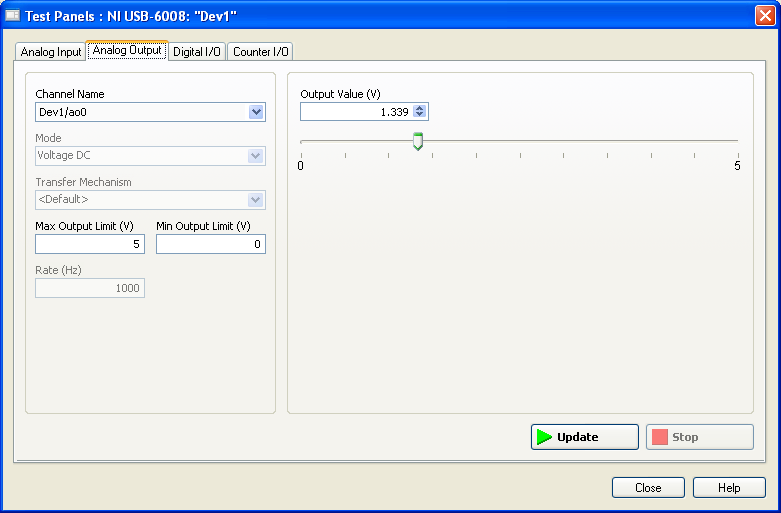
the analog output works very well since I plugged it to my multimeter and I can see the tension that I see on this Panel of test:
http://i284.Photobucket.com/albums/ll5/bigdawg6/AO0%20screenshot_zpsqpei37bw.PNG
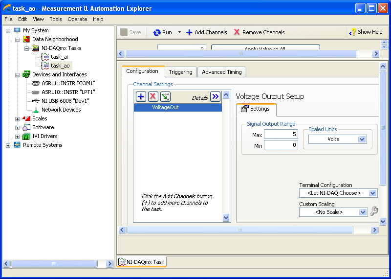
I created an entry/exit of the tasks; screenshots of them are:
http://i284.Photobucket.com/albums/ll5/bigdawg6/task_ao_zpsykmvczew.PNG
http://i284.Photobucket.com/albums/ll5/bigdawg6/task_ai_zpsix5se9yg.PNG
I am quite frustrated with all this since I'm unable to access my actaul draft. I know that 1.4 V value is from the device itself; as in the manual it says 'internal resistance divider can cause the Terminal to float at about 1.4 V when the analog input terminal is configured as a CSR', but the funny thing is that I use it in differential mode so I don't know what to do and any help is appreciated.
BTW, I did a google search and there are other tutorials onlune who seem to do exactly what I do and they seem to work very well; so I don't know what else to do.
Please don't host images on some odd third-party site. Attach them to your message.
I don't understand what you've done. The 6009 can produce only a signal of CSR in order to set up the differential input makes no sense. If you want to measure something different, try a simple battery.
-
Pt100 (USB-6008) configuration problems
Hello
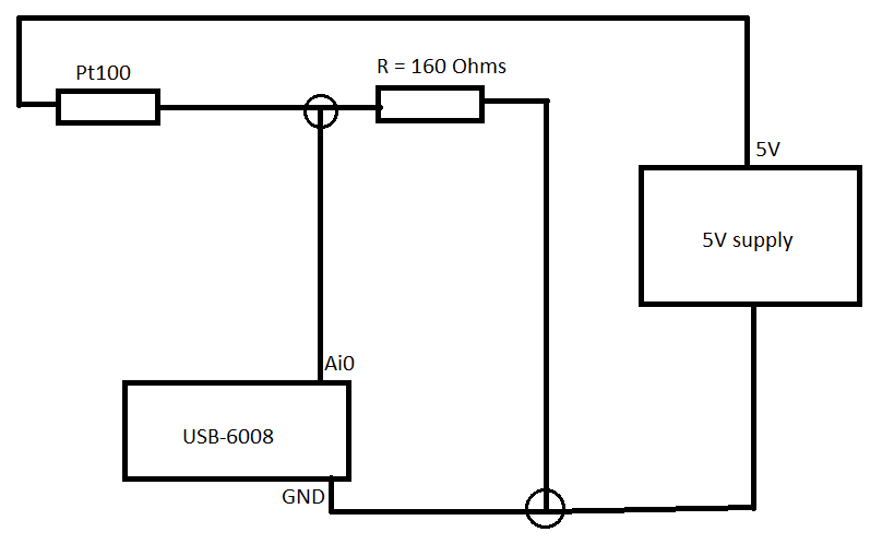
I'm using the hardware DAQ USB-6008 (I know that's not accurate and all) and I use the Pt100 (QAP2010, click for plug technique).
I connected it like this.
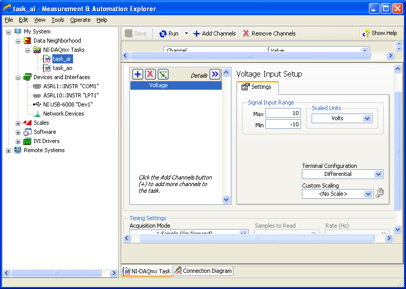
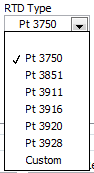
Now in LabVIEW, these are the only options (DAQmx new task-> acquire->-> RTD temperature signals).
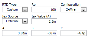
If I choose for custom settings, I get these options (I don't know what variables that is).
I use a small greenhouse where I need to measure the temperature and humidity and control environment (by using a fan to cool the cartridges to greenhouse and heat to heat).
My goal is to read the temperature using a graph on the front panel.
Can someone help me how configure/choose the right options? If you need more information I'll provide them as soon as possible!
A quick search for RTD class B shows the precision and the coefficient. As Fan Ravens stressed resistance according to the temperature is plotted in the data sheet. To control the temperature in greenhouse, a simple calculation of the slope of this graph is not good enough.
Note that the USB-6008 case limited an active player on the outputs analog and it controls only the voltage. So you will need at least one external resistor and possibly and external power to excite the RTD. These options that you have linked is not applicable to the USB-6008, which is a very simple device. You should perhaps simply to measure the voltage and calculate first resistance, then the temperature.
Lynn
-
NEITHER USB-6008 connect to thermocuples and pressure sensors, control valve
I am endevoring to build a gasification plant biomass for bench scale test process control plans. NEITHER USB-6008/6009 will be adapted for use as a data acquisition. I'll take RTDS, thermocouples and pressure sensors. I don't want to use industrial automation controllers. It is also possible to use the channel of analog output for sending signals to a control valve position (using sufficient current/voltage between the two drivers).
(1) OK. I just wanted to be sure that you were aware of the potential dangers.
(2) an RTD is a resistance that has small changes in resistance per degree of temperature change. To measure that you have need of a current source and a sufficient resolution in order to detect small changes. At 25 degrees C a typical RTD is 109,73 ohms and resistance ohms 0.38 per degree changes. If you had 1 my crossing this RTD voltage through it would be 109,7 mV and the voltage change of 0.38 mV by degree.
The resolution of the 6008 on the most sensitive range is 0.49 mV > 1 degree. The accuracy of the 6008 is 1.5 mV typical.
For a Type K thermocouple, voltage at 25 degrees is 1.407 mV and change by degree is 39 µV. Millivolt solving half of the 6008 translates into about 12 degrees.
If you need a source of excitement for RTD and a kind of amplification for thermocouples and RTD before she would make any sense to try to use USB-6008.
(3) I have not used anything except LabVIEW with DAQ devices and drivers. I think DAQmx can be used with MATLAB and other languages.
(4) the 6008 is the low range made by NOR. You will need to go to a more expensive camera or add signals conditioning circuits. Talk to your representative OR assistance in the choice of a suitable device.
Lynn
-
E/s digital USB-6008 changes when the system starts
I was intending to use the USB-6008 housing in a critical application in which the digital I/o lines are used to trigger relays. The relay should activate when I ask them programmatically. Otherwise, they must remain open. The problem is that during a reboot of the operating system, the e/s digital USB-6008 go up and down several times - opening and closing my relay. It is not acceptable for my application.
Is it possible to prevent the lines to reach logical high except if ordered to do so?
There is no way to set the startup on the 6008 States.
As the system USB boot devices and turns on power to the computer and off the power to the USB ports, on the DIO lines go up and down several times.
You will need to put a logic of material extra, just after data acquisition to ensure that potentially dangerous output combinations cannot affect the relay and the elements they control.
-
New to Labview, need help. USB-6008
Hi there, let start by saying, I'm totally new to Labview. I have experience of programming in C, C++, VB etc, but never in Labview. I thought that Labview is not much of a difference, but I was very wrong. I went and bought the acquisition of data USB-6008 and downloaded the trial labview to explore and I am totally stuck and have no idea how to proceed. I can start over again and probably learn all the basics, but I don't want to take too much of my time. in any case, here is a description of my project:
Configuration: USB-6008 - to measure the voltage of a battery lithium ~3.6V
Circuit printed with a switch either connects the battery resistance or not. the switch can be turned on and off by a USB-6008 analog voltage output
What I want to do in pseudo-code:
If you click START,
Take a read of DAQ and shop to chart and indicator of voltage 1
If the voltage is > 3.6, then
30 seconds
a voltage data acquisition to turn on the switch and light load lights output
read DAQ and update graphic and indicator of voltage 2 reading
If it is DAQ< 3.5,="" status="" indicator="OFF," else="">
30 seconds of the end loop
If the last reading after 30 seconds of DAQ is > 3.5, the message 'pass' else a message "fail".
on the other
indicate a voltage lower than 3.6V and stop the program
end if and stop the program.
NOTE: the voltage indicator 1 show ONLY the first reading before the circuit switch is on.
I didn't know that it is very difficult to program, because everything is very basic, but since I don't know Labview, I do not know how to proceed. a front is attached.
Thank you for your help.
John
Hello!
To start, here are a few things.
1. learning LabVIEW:
This has all kinds of videos step by step based on LabVIEW and is a great resource just start... it's really great because you can click on a video about any topic that interests you. There are a set of tabs at the top that categorize videos.
2 examples of DAQ. In LabVIEW go to the Help menu > examples of find... Then in the window that opens (this is called the Finder of the example) you can navigate to the material file Input and Output > DAQmx > Analog measures > voltage
We have tons of DAQ examples, so this should at least allow you to read a voltage quickly.
I hope this helps!
-
USB-6008 appears in Device Manager but not in MAX or Labview
I use Windows 7 Ultimate 32-bit and you want to use a USB-6008 in LabVIEW 8.5.1. The device appears under data acquisition devices in the Windows Device Manager. The flashing on the device, but the device does not appear in the Explorer of Measurement & Automation 8.7.1. am I missing something?
He doubts.
First, check the easy things... to refresh the list of devices to MAX and see if it comes to that. I'm guessing you've already tried this, but it never hurts to check.
My bet is that it's a database corrupted Max. This happens from time to time. Usually when I see it, the 'Dev1' always appears in LabVIEW if you plop down constant DAQ hardware or control.
There are tools and processes to erase and start over with a new database, but in my experience, the best way to resolve it is simply update or reinstall MAX.
-
How to connect my potentiometer (3 connections: wine, Vout & amp; common) to USB-6008
Hi looking for help connect my knobs to my DAQ USB-6008. Essentially got some linear and chain of pots that will be connected to the fitting of the parts to give a linear movement of DC output voltage. Got DAQ USB-6008 DC output read and display in LABview.
The pots have 3 electrical connections:
1 input voltage
2. output voltage
3 common
Entry and common connections are connected to my power supply DC leaving a single output voltage wire.
1 should I connect DAQ in premium or CSR mode?
2. as I have only a single output connection (as input and common are atttached to food) what can I connect to GND mode CSR (or the terminal for the differential mode - ve)? Can he remain unconnected?
3. do I need to connect anything to the output of data acquisition channels? or data acquisition will read my entries and display them in LABVIEW?
Excellent. Thanks for your reply. Think about it, as I have many pots to connect up to this unique DAQ so if I use the DAQ outputs to power pots, then I would be limited to two pots on the DAQ specification?
If I use the other method and hang the pot common and input for external power supply-/ + terminal and the hook to the top of the pot then you suggest also, I need to pin 1 ground output to the AI1 on data acquisition. What is all the Earth? What do you suggest as a land? If I go down this road then allow me up to 8 pots on this data acquisition? (And I guess each other the GNDs would also need to be connected to each other input used?)
-
Cannot find the Web site buttons that I pulled down on the toolbar
I pulled down the buttons on the menu bar, saved the 'Export' menu bar as a html file and cannot locate the file on my desktop.
lucienalta said
I pulled down the buttons on the menu bar, saved the 'Export' menu bar as a html file and cannot locate the file on my desktop.
Nevermind, I restored it. Thanks for the research.
-
recently and without other changes that I'm aware of my thunderbird pull down menus do not fill with text, or do sporadically after the period of 15 to 30 seconds.
Try this.
https://support.Mozilla.org/en-us/questions/1012145I'm guessing so please let me know how it goes.
-
Reading NI USB 6008 of executable
Hi all
I tried to find a solution in existing topics, but unfortunately could not find a suitable solution.
I use a USB-6008 read a voltage on ai0. When I run the VI with the USB device connected to my development pc it works very well (DAQ assistant was used to read the value on ai0). After making an executable on my development pc also works. However, when I move the executable file on the computer on which I want to use it does not read voltage. If I start NI Max, I noticed that the computer is able to read the value, so physically everything should be good. To me, it seems that some link/link is missing from the software. Anyone know what may be missing/defective in my executable?
OR DAQmx is installed on the computer on which it is to run.
Is the device and channel named in the same way on desktop deployment as was the development of your PC? Display the MAX on each PC and compare.
-
USB 6008 weird analog voltage reading
Hello
I use the USB-6008 to measure a voltage of a Lithium battery, 3.66V.
the battery come with a blocking diode (in series with the battery) of 1N5820, who have a fall of voltage drop of 0, 1V.
battery with diodes in series (this is the way in which the battery is shipped with)
-measure with DDM yield 3.66V without you connect to usb6008
-measure with DDM yield connected to usb6008 (putting OUT VOLTAGE USB6008) 3.59V
-able with USB-6008 performance 3.59V connected to usb6008
battery with diode removed
-measure with DDM yield 3.66V without you connect to usb6008
-measure with DDM yield connected to usb6008 (putting OUT VOLTAGE USB6008) 3.66V
-able with USB-6008 performance 3.66V connected to usb6008
Thus, it seems that the problem is in the led in the series. This is why the battery voltage has fallen to 0.07V? the series diode will hurt the USB-6008?
Maybe people who know the circuits inside the USB-6008 can give me an answer.
Thanks in advance.
Hi learnerd,.
The fall that you see is falling forward in the diode. As an entry class device, the USB-6008 case has a relatively low input impedance (144kOhm) and thus draws a little current of the device. Looking at the datasheet of the 1N5820 (http://www.onsemi.com/pub_link/Collateral/1N5820-D.PDF), Figure 7 shows that at 25 ° C, a draw of 50mA will cause a fall front of 200mV. While the figure does not extend the curve below 50mA, extrapolating the given curve would indicate that a drop of 70mV would cause only a few current microamperes.
A DMM will have a much greater input impedance (GOhms instead of kohm) and won't draw enough current to influence the measure, that's why you wouldn't see the decline with only the DMM.
The diode will not harm the USB-6008 somehow.
Good luck with your application,
The f
-
MAX and Mac (to control on Labview, NI USB-6008)
Hi, I would like to order my USB NI 6008 card in my Mac. I'm using Labview, but I'm a real beginner. I get my sensor on my USB card data and I can use them in Labview to control an electric trolley. This project is for my review: engenering school.
So, on PC (Windows), it's ok, but on my mac, I do not find MAX. And if I understand, I need MAX to create the DAQ Assistant and a few other VI in Labview. However, I have yet install Base DASmx 3.4 for mac os.
Could you help me please?
I'm sorry for my English, it's so bad. I'm studying french and I'd rather post here because I found no answers in the french part of forums of NOR.
See youi soon.
Thank you
Thomas L
The USB-6008 camera is supported with DAQmx Base, Yes. You do not get MAX, but you can always control your USB-6008.
Install LabVIEW 2010 and DAQmx Base 3.4and this should give you the DAQmx Base vis in LabVIEW palettes.
Maybe you are looking for
-
I don't want automatic full gmail user names or other sites
Even now, when I signed up for my question, as soon as I typed the first letter of my semiautomatic entered user name gave me the options that were used. I accidentally typed a password right after a user name before and now also pop in option. I tri
-
How to download a compatible version of onipad version 5.1.1 solitaire card
How can I download a compatible version (older) maps and lonely spider on an older ipad running the version 5.1.1?
-
Computer freezes constantly after being inactive for some time (windows vista, 32-bit)
After 5-10 minutes of inactivity, the PC crashes, not alt + f4, not ctrl + alt + delete and no more choice, JUST! He can turn off my laptop! I'm going to be psychotic...
-
I have a CQ60. Since the day where I bought it with vista on it, I had problems with wireless. He drops the wireless randomly. It is not a hardware problem, I installed XP Pro above and it works flawlessly for months. I put Windows 7 32-bit on it and
-
Official ram type for HP Pavilion g6-1156ee
Hello I have HP Pavilion g6-1156ee laptop, I would like to know what type of official ram supported by HP for this laptop. as I want to increase the ram to 3 GB (1 * 1 GB and 1 * 2 GB) to 4 GB (2 * 2 GB). Thanks in advance