USB 6008 weird analog voltage reading
Hello
I use the USB-6008 to measure a voltage of a Lithium battery, 3.66V.
the battery come with a blocking diode (in series with the battery) of 1N5820, who have a fall of voltage drop of 0, 1V.
battery with diodes in series (this is the way in which the battery is shipped with)
-measure with DDM yield 3.66V without you connect to usb6008
-measure with DDM yield connected to usb6008 (putting OUT VOLTAGE USB6008) 3.59V
-able with USB-6008 performance 3.59V connected to usb6008
battery with diode removed
-measure with DDM yield 3.66V without you connect to usb6008
-measure with DDM yield connected to usb6008 (putting OUT VOLTAGE USB6008) 3.66V
-able with USB-6008 performance 3.66V connected to usb6008
Thus, it seems that the problem is in the led in the series. This is why the battery voltage has fallen to 0.07V? the series diode will hurt the USB-6008?
Maybe people who know the circuits inside the USB-6008 can give me an answer.
Thanks in advance.
Hi learnerd,.
The fall that you see is falling forward in the diode. As an entry class device, the USB-6008 case has a relatively low input impedance (144kOhm) and thus draws a little current of the device. Looking at the datasheet of the 1N5820 (http://www.onsemi.com/pub_link/Collateral/1N5820-D.PDF), Figure 7 shows that at 25 ° C, a draw of 50mA will cause a fall front of 200mV. While the figure does not extend the curve below 50mA, extrapolating the given curve would indicate that a drop of 70mV would cause only a few current microamperes.
A DMM will have a much greater input impedance (GOhms instead of kohm) and won't draw enough current to influence the measure, that's why you wouldn't see the decline with only the DMM.
The diode will not harm the USB-6008 somehow.
Good luck with your application,
The f
Tags: NI Hardware
Similar Questions
-
Want a ramp of output voltage over time and measure input 2 analog USB-6008
Hello
I want to produce an analog voltage output signal that increases over time with a certain slope, which I'll send in a potentiostat and at the same time I want to read voltage and current (both are represented by a voltage signal) that I want to open a session and ultimately draw from each other. To do this, I have a DAQ USB-6008 system at my disposal.
Creation of the analogue output with a linear ramp signal I was possible using a while loop and a delay time (see attachment). Important here is that I can put the slope of the linear ramp (for example, 10mV/s) and size level to make a smooth inclement. However when I want to measure an analog input signal he's going poorly.
To reduce noise from the influences I want for example to measure 10 values for example within 0.1 second and he averaged (this gives reading should be equal or faster then the wrong caused by the slope and the linear ramp step size.) Example: a slope of 10 mV/s is set with a 10 step size. Each 0.1 s analog output signal amounts to 1 mV. Then I want to read the analog input in this 0.1 s 10 values)
Because I use a timer to create the linear ramp and the analog input is in the same loop, the delay time also affects the analog input and I get an error every time. Separately, in different VI-programs (analog input and output) they work fine but not combined. I searched this forum to find a way to create the ramp in a different way, but because I'm not an experienced labview user I can't find another way.
To book it now a bit more complicated I said I want to measure 2 input analog (one for the voltage of the potentiostat) signals and one for the current (also represented by a voltage signal) and they should be measured more quickly then the bad of the analog signal. I have not yet started with because I couldn't read on channel work.
I hope someone can help me with this problem
An array of index. You want to index the columns for a single channel.
-
DAQ USB-6008 will be able to power and record voltage for UMS T5 blood pressure at the same time?
I would use my NI USB-6008 to power my blood pressure monitor UMS T5 (http://www.ums-muc.de/en/products/tensiometer/t5.html) but also to take readings of it, but I don't know if it's possible to do it properly. The power supply for the instrument can be as low as 5V, I can easily get the dedicated + 5V channel. I'm able to feed the instrument and connect it to an analog input on the 6008 and measure a voltage in differential mode. However, when you read the documentation of support for the instrument, I find the following:
"Potential pitfalls of data acquisition: the pressure transducer is configured in a full Wheatstone bridge, the input voltage and mV signal output can be connected to the same reference (mass)." Therefore, the mV output signal can be measured using a differential voltage measurement. Therefore, do not make an asymmetric measure of pressure transducer mV output. "(http://www.decagon.com/assets/Uploads/MeasuringUMSTensiometerswithnon-UMSControlandDataAcquisitionSystems.pdf)
My understanding is that the 6008 can take a differential measure if I attach the signal '+' and the signal "-" to the analog inputs of positive and negative terminals. However, it seems that all the ports of ground on the 6008 are grounded to the same reference, which would make my measure of invalid tension according to the above paragraph. So my real question is: if I try to record the voltage with one of the analog inputs on the 6008 in this way, is the valid measurement? Or I need to find a separate power supply, with a different reference field to ensure that the measure is accurate?
The technical details of this device is very poor. The manual is not much better. Companies that want to sell scientific equipment should publish decent cards or get out of business.
In section 3.4.3 General requirements the device is described as a "bridge not amplified circuit. This information along with the impedance of the bridge should be in the specifications, because it is essential to apply the device under any circumstances other than the nominal behavior in 10.6 V.
The answer to your question is:
You can use it with the box USB-6008. The 5 V supply will result in output voltages a little less than half (5/10.6) the voltage specified in nominal conditions. You can use the differential input mode on the box USB-6008. The absolute input voltages will be approximately 2.5 V with the 5 V power supply. This voltage is in the range of the aircraft. The differences are likely to be less than 100 mV. The resolution of the USB-6008 on the + /-1 V is located about 0.5 mV so your resolution of pressure will be about 1% of full scale. The voltage input impedance and termination of the USB-6008 will present a few errors. These can be in the order of 5 to 10%. I can't predict much better without the missing bridge impedance specification. These errors should be relatively constant and systematic. A calibration of the whole system - sensor and together hardware DAQ should allow you to compensate for a large part of this error.
Lynn
-
Beyond the limits of voltage on USB 6008?
I use a USB-6008 to measure analog differential in the range of 3 to 5.3 V. I chose this range, because outside this range, I'm not interested in what the tension is, knowing that his "on the rail", but to aid resolution of the ADC in this range.
So for a signal of ~0.05 supply V, I expected to read 3V, telling me that the voltage is lower than 3V, but again it returns 0.05v?
As it was unexpected for me, could someone please explain what can / should I expect of my USB6008 of the responsed to the signals that are the limits? Is there an effect of "rollover"? Should you return the value to the limit? Depends on how far the limit is?
Thanks for your help!
Entry level do not think that way. You specify the range is that you wait for the signal and the DAQmx driver will set the most appropriate range that the device supports. The actual ranges are indicated in the guide. In your case, because you specify a max of 5.3, the device would be defined the +/-10 volts range.
-
NEITHER USB 6008 voltage offset using CSR and measurement of diff.
Hi all
I am currently trying the NI USB 6008 housing and I'm getting problems when reading voltage analog using CSR or differential.
So basically, what I want to measure is a PWM signal (0 to 12V), which is divided by a divisor of tension (by two). But instead of measured 0V and 6V
I am in a position a constant 0.8V and approximately 3V.
On the side of digital data acquisition, I give you on impulses for the SSR... and it works fine.
I connect it that way: http://digital.ni.com/public.nsf/allkb/95CC0CB11D7DF3D18625712E000C4ABD?OpenDocument
Would apreciate any help
Best regards
EDIT: Attached graphics acquired are
What is the impedance of your voltage divider? The input of the USB-6008 impedance is not very high. If the impedance of the partition is large, it could cause the effect you see.
Lynn
-
USB 6008 analog i/o has stopped working
Hello
I have been using a USB-6008 for a few weeks now and it has worked well. I've been using the outputs digital, analog inputs and outputs this morning and they worked very well. I worked on something else for an hour or two and then resumed using the 6008, find the analog pins have stopped working. The show output analog on 1mV any value I send to them and the analog inputs always read - 10.3, despite limits MAX being set to 0 and + 5 (and me only using 0 - 5V on them). I tried all the inputs and outputs, in all ways (CSR, diff) with the same results. The digital outputs all work very well. Yes, he is grounded properly. Yes, the wires have continuity. My multimeter don't lie about me, either.
I took the MAX test panel to solve the problems. The unit passes its tests of self-control, and my Labview program does not return errors by contacting the 6008. I don't connected the 6008 which could exceed the voltage or the current limits of entrances and exits. In fact, all I did was unplug it when I stopped using it as soon as possible and then reconnected it when I went back to work. The material to which it is connected has been turned off during this time.
Any ideas? Thank you.
Problem is solved. If anyone finds this is interested, the problem was at the level of the material, that the 6008 has been connected. I'm covering, among other things, to a PIC Microcontroller. I just changed the oscillator on the PEAK, and inadvertently changed parameters parameters of the ADC as well. This caused the pin used as my reference voltage (connected to + 2, 5V output of 6008) to transform itself into a digital camera of output, a value of 0. This short-circuit the + 2, 5V output of the 6008, causing it to close.
Lesson learned: check your material carefully, even if it does not make the difference in a first time!
-
USB-6008 LABVIEW 8.2. SINGLE CHANNEL WITH DBL INPUT VOLTAGE OUTPUT COMPARISON
I AM WRITING A PROGRAM THAT USES A SIMPLE USB-6008 ANALOG INPUT CHANNEL. I WANT TO READ CONTINUOUSLY THE VOLTAGE FOR 60 SECONDS. I WANT TO COMPARE A TENSION FOR THE PREVIOUS OF THIS SAME CHANNEL VOLTAGE, MAINLY FOR THE PERIOD OF TIME MAX VOLTAGE GIVEN, THEN GET A FINAL VOLTAGE READING. THE OUTPUT OF THE VI IS A DBL. I WANT ONLY TWO TENSIONS OF EXPORT TO EXCEL. TO SAVE TIME, I KNOW HOW TO EXPORT. CAN SOMEONE HELP ME WITH THIS ONE.
VI needs an register shift related to the Max & Min function. The current value would be the entrance is and the entrance of x is the left shift register. The max value gets wired for the shift register to the right. Don't forget to initialize it. The output of the shift register is the max you would write and the value of the DAQmx Read out of the loop of wire will give you the last reading.
Your waiting for 45 seconds makes no sense since you said that you wanted to read continuously. You also said that you wanted to read 60 seconds and all this logic is missing. A simple function of time elapsed, it's all you need.
-
Reading USB-6008/DAQmx sampling
I use LabVIEW Student Edition 2009 with an acquisition of data USB-6008 on a Windows 7 computer. I must confess that I am rather self-taught in LabVIEW and may lack in fundamentals.
I wrote a code to move motor back with a sine wave with the 'Signal to simulate"VI and VI"DAQmx Write. " I think that this part of the code is OK but its probably sloppy.
The part that that concerns me is the "DAQmx Read" part - I use this to get a feedback of the motor position on an analog scale 0 - 5V via the port of AI1. I also use this DAQmx Read to get another feedback voltage from a force sensor that feels the force in a piece of material set by the engine. I want the information to all-terrain such as graphs or tables with the last 30 seconds, and then a value of information, but that's all I want to see since this cycle repeats for hours. I also need to process this information - if the strength of the material gets high, I need to stretch less etc. So far, everything is working fine, but now I want to use the "peak detector" VI for expressly that the "peak" of the sine wave is part of a certain range of strength and the '' Valley '' falls into a second range of force and clearly since I read this information as a single integer/sample there is no 'memory' of the last seconds in the form of a table of examples past or a waveform or something like that I can't detect the peaks.
So my question is - should be sampling this information differently to temporarily store information (such as a waveform or something?) or should I use individual samples to build a continuous array for the last 30 seconds? In other words, what is the best way to read this information in a way that will make it easy to detect the peaks on the final seconds, but not to store hours of endlessly repeated information? I also want the release of LabVIEW and feedback from the system graphics to match so that the signal sent to the engine for the same positional signal back to LabVIEW from the engine. I should add that I do not know if the system works in real time or on a little late, but nothing like over delay of 30 seconds.
I have attached a code that I use to calibrate my system - is not the same as I mentioned earlier, but things 'DAQ read' are the same and you get the idea with the rest of it. I can also reach more detailed code if it would help.
Yet once again, I'm sorry for my skills of coding bush-league and thanks for any help!
-Chris
If you always use a waveform chart to display your data and your happy with length of time of the chart, you can use the 'Historical data' property node for recover your data from 'short term' gathered. From there, you take the data and make a type of waveform data using the 'build' primitive waveform.
-
NEITHER USB 6008 tension problem reading
Hello
I am trying to program a USB-6008 on a mac. When I connect to the input to analog 5V output I get a reading of 3.67volts, while on an osscilascope, I read a 5volts voltage. Is this normal? Need to load resistors? Also, I get the same effect with the release of tensions for the analog output.
Hi Zepp2,
Thanks for your post. The pins are you connect together on your device? Depending on the type of connection you have the wiring may not be quite right.
I found a few documents online which hopefully should help you:
Field of connection for analog signals: http://zone.ni.com/devzone/cda/tut/p/id/3344
USB-6008/6009 Getting incorrect voltage reading: http://digital.ni.com/public.nsf/allkb/95CC0CB11D7DF3D18625712E000C4ABD?OpenDocument
Input analog USB-6008/6009 reads about - 1.4V Offset: http://digital.ni.com/public.nsf/websearch/E687933C5694AB00862570BD00593CA3?OpenDocument
Please let me know if one of them will help out you.
Kind regards
-
Reading NI USB 6008 of executable
Hi all
I tried to find a solution in existing topics, but unfortunately could not find a suitable solution.
I use a USB-6008 read a voltage on ai0. When I run the VI with the USB device connected to my development pc it works very well (DAQ assistant was used to read the value on ai0). After making an executable on my development pc also works. However, when I move the executable file on the computer on which I want to use it does not read voltage. If I start NI Max, I noticed that the computer is able to read the value, so physically everything should be good. To me, it seems that some link/link is missing from the software. Anyone know what may be missing/defective in my executable?
OR DAQmx is installed on the computer on which it is to run.
Is the device and channel named in the same way on desktop deployment as was the development of your PC? Display the MAX on each PC and compare.
-
Hello
I just started using an NI USB-6008 box. At this point, I don't need to fill all the specific tasks other than learning to use the device. I used a fair bit of LabVIEW but never with this kind of material, and I would like to help to understand it please.
In particular, I have attached a VI in which I try to get an analog signal through the USB-6008 and read again (also with the USB-6008 - I wired the pins together). However, I do not understand what is happening when I run this VI. I expect the output a sine signal of 10 Hz for 1 second, 0.1 seconds record and see 1 full cycle of the sine wave. In practice, I read about 10 cycles and constant tension then. Presummably, this means that either the reading continues for more than 0.1 second, otherwise the output signal is more than 10 Hz.
I also tried to use the related calendar DAQmx screws with the output pin to try to adjust the output rate (samples/s) but everything that I've tried return errors. I also tried to open some examples NOR, but these errors returned as well and I still just try things on mine.
Did I miss something obvious here, but any help would be appreciated!
Edit: I had to update this post & attached VI I had made mistakes. The default values on the front panel show what I see after the execution of the VI.
Orbital Hi,
As far as I know, you will need to use the DAQmx Read and VIs write in loops and functions of synchronization to determine data rates you want.
I also did a quick search and found a white paper which you may find useful: http://www.ni.com/white-paper/9541/en/
Kind regards
-
I can read two-channel USB-6008 using THE Signal Express?
Hello world!!
Is possible to read the two analog inputs at the same time?
Example: Using Signal Express, I need to read the (channel 0) analog input and analog input (channel 1) at the same time.
I try this but, the signal on purpose gives me an error message saying that I can't read several channels at the same time using the USB-6008.
Is this true?
Thank you
Ivo João
André,
Grato definition of pela.
SUA ajuda muito util faith.
SDS,
Ivo João
-
Measurement of voltage USB 6008 ranging from 1mV
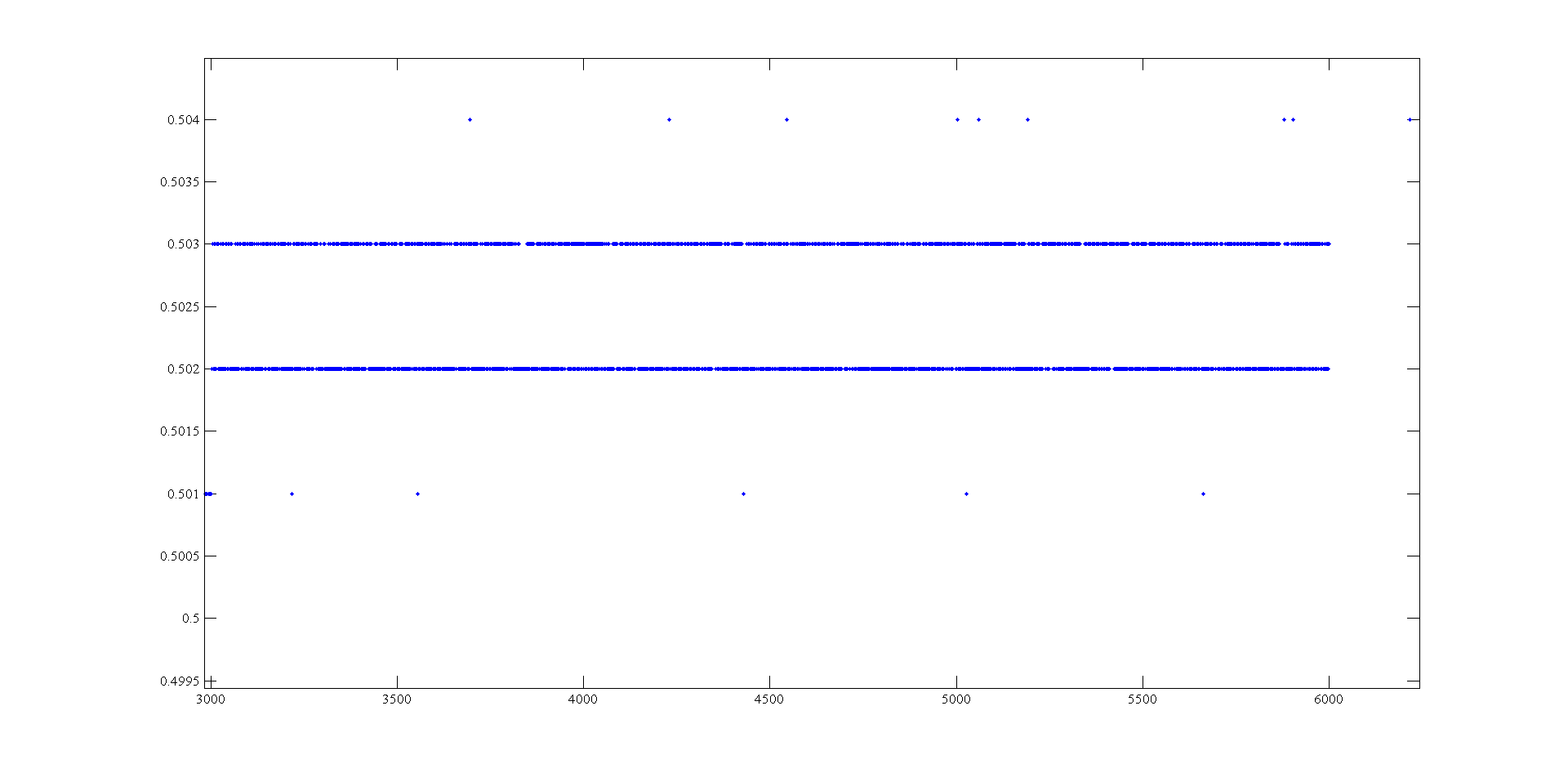
Hi, I'm doing a supply at an angle for an amplifier using the USB-6008. The ranges I look are - 0.5 to 0.5 V and 0.5 to 2.5 V. To generate negative tensions, I use the + 2, 5V for a reading of differential voltage output as a 'ground '. Voltage measures have a delay that varies with the voltage, given this by drawing these variations and set the output to data acquisition there is still a 'noise' of +/-1 mv so that it is clear from this parcel of tension against the sample number:
It seems that at some point the values are being rounded up to the nearest millivolt. I need to get to a resolution of 0.5 mV for my device, it will be possible with the USB-6008?
The AO USB-600 x has a range from 0 to + 5 V and the 12-bit resolution. 5/4096 = 1.22 mV. Absolute precision is 7 mV typical and 36.4 mV maximum full scale. The noise of the AO is not specified.
If you measure the results with THE USB-6008, you have at least 0.5 mV, similar resolution system noise and absolute accuracy of 2.5 mV or more.
It's probably as good as you will get with the box USB-6008.
Lynn
-
Can I use five differential signals analog usb 6008?
Hello!
I have the USB-6008 housing with one and two potentiometers temperature sensor (and one meter and digital input is also beign used).
I've only got analog +-left slot but I still need to connect the voltage and current signals of a diet. Is it possible to have both connected somehow to the last + slot?
If it is not possible what harware would you recommend instead of the 6008?
6211 next best step up that gets you more AI.
Alternately, you could just put a 2nd 6008 in the system... certainly cheaper than a 621 x.
-
How stable is the long term outputs analog USB-6008?
The USB-6008 datasheet do not specify the stability long term of the analog inputs and outputs.
I'm looking for stability compared to the ambient temperature and time (several months to a year), mainly for the outputs or the D/A reference voltage.
Is there any information available?
Thank you.
The precision specification takes into account the evolution both because of the temperature and duration (stable). Thus, for the period of a year that we guarantee these specifications, which list you is correct. However, apart from the period of one year since the calibration, this specification may be is more inaccurate.
Maybe you are looking for
-
Just as I suspected, I'm a bunch of predetermined responses. Where can I put the power to Mozzila a question about my particular problem? Do not give a lot of your presumptuous answers.
-
How to install Windows XP in Pavlion dv6-2114sa?
I bought this machine and then to find some of my software, which is essential to the work, can run only not on Win7. Therefore, I have this downgrade to Windows XP. After I tried all the solutions that I can find here and also Google, I always got a
-
Required sind Welche Trainingsprogramme
Hallo, bin just courses auszusuchen mir dabei. Da das sehr weitlaufige ist eure Hilfe ich brauch Kursprogramm! Mein Ziel ist're mit OR different Lin und can participants zu taxes und dabei verschiedenste reports (Strom, Errorbits...) aufzunehmen. The
-
I am reading data inport hexagonal form and save it in the table to compare the data with 0100800000D 0... How can I make hexagonal constant array to store the 010080000D 0... and then compare it with the table that store data of inport... (In fact
-
Hallo, DAS wanted Update kann sich auf meinem PC nicht installieren und kommt wieder anyone therefore. Wie kann ich das abstellen. bzw. Warum sich der nicht Patch installed?