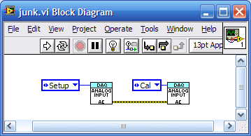
USB-6221, replaced by USB - 6221 BNC - error-50103
My client is reproducing a system that worked well with NI USB-6221 enclosure. Now, I get an error with the NI USB-6221 BNC. The error only occurs when I try to perform auto calibration.
---
The error:
Error-50103 occurred at DAQmx Self Calibrate.vi:1
Platform AND Services: The specified resource is reserved.
---
I've implemented the pilot as a driving force.
What is strange to me is that I can run the engine of the autonomous action to set up the device and run the auto cal without getting an error. But when I call these routines of an another vi - the error occurres.
To specify (and reproduce the problem) - with USB-6221 BNC is defined as 'dev1 ':
(1) acquisition of analog data in AE.vi - select 'Configuration' as an action on vi and then run it
(2) acquisition of analog data in AE.vi - select 'Cal' like action then don't run it - no error
(3) place the screw DAQ in a new vi as shown - run and that's when I get the error
This is my first experience with DAQmx, any ideas what could cause this problem would be appreciated.
Thank you
Steve
LV2009 Sp1
MAX 4.71
NOR-DAQmx Device Driver 9.2.1
Hi Steve,.
"Setup" action leaves the DAQmx run task, so the 6221 AI resources are reserved to prevent other programs and live to interfere. When the top-level performance, LabVIEW VI automatically tells DAQmx to clear the task. That's why you get different behavior when you run the action as the first level VI engine when you run the engine of the action as a Subvi. Self-cleaning, you must cancel (e.g. stop or clear) all the tasks before you can calibrate the device automatic, try performing the action 'Close' before 'Cal
Brad
Tags: NI Software
Similar Questions
-
The channel numbers and the USB-6259 BNC
The front panel USB-6259 BNC labels BNC connectors as channels 0-7 and 16-23. Most odd... I have a software written in C++ using NOR-DAQmx that my client will try to use with this unit. When using the channel superior numbers he (not unusually, really) Gets the error-200077 saying that they can only be used in unbalanced mode. But it is not natural for him to use the channel numbers printed on the front of the unit.
Can someone tell me how the front panel of this device is the channel numbers, you must specify in the code?
This requires the switch (source of the source/grounded) floating FS/GS that appears under each BNC connector?
Here's my proposal: differential mode: in the software, channels 0-7 are front channels 0-7. Software 8-15 channels are front 16-23.
Asymmetric mode: software channels 0-7 are cover 0-7 and 16-23 software channels front 16-23. And 8-15 and 24-31 channels are absent...
It takes just the opposote of what you have. In differential mode, aix is paired with aix + 8. so, ai31, ai9, AL10, ai11, ai12, ai13, ai14, ai15, ai24, ai25, ai26, 27, ai28, ai29.ai30 and ai8 channels are not available for selection in differential mode. Front panel for ai15-23 labels should be correct and matches what you select in the software.
-
I want to integrate the ANSI C sample program ReadDigPort - ExtClk.c in my own big package.
I want to use the internal clock of the BNC NI USB-6259 (.. 80 kHz 120 kHz).
In the document:
High speed M: Series Multifunction DAQ for USB - 16-bit, up to 1.25 MECH built-in BNC connectivity. / s,.
is written:
Or sample DI source clock: Any PFI, RTSI, HAVE sample or convert clock, AO, Ctr n out internal and many other signals sample clock
The digital subsystem doesn't have its own dedicated internal synchronization engine. Therefore, a sample clock must be provided another subsystem on the device or from an external source.How can I use internal clock case OR USB - 6259 BNC for the acquisition of digital data in my own big software?
With what other subsystem on the device can generate a source of the clock? How?It is possible to set a clock on an internal counter (for example ' Dev1/ctr0"):
Creates channels to generate digital impulses that define the freq and dutyCycle and adds the channel of the task that you specify with taskHandle.
DAQmxCreateCOPulseChanFreq (taskHandle, "Dev1/ctr0" units, clockName, idleState,
initialDelay, freq, the duty cycle); worksBut it is not possible to drive this internal clock to a terminal (for example "/ PFI0/Dev1"):
DAQmxErrChk (DAQmxCreateCOPulseChanFreq (taskHandle, "/ PFI0/Dev1", clockName, units, idleState, '))
initialDelay, freq, the duty cycle); does not work: error DAQmx: measurements: type I/O of the physical channel does not match the type of I/O required for the virtual channel you create. Name of the physical channel: PFI0. Name of the virtual channel: clockThe sample clock source can be derived from an external terminal (for example "/ PFI0/Dev1"):
Sets the source of the sample clock, the sample clock rate and the number of samples to acquire or generate.
DAQmxCfgSampClkTiming (taskHandle, "/ PFI0/Dev1", maximumExpectedSamplingRate, DAQmx_Val_Rising, ")
DAQmx_Val_ContSamps, bufferSize); works. Acquire or generate samples until you stop the taskBut it is not possible to derive the internal counter of the clock (for example ' Dev1/ctr0"):
DAQmxCfgSampClkTiming (taskHandle, "Dev1/ctr0", maximumExpectedSamplingRate, DAQmx_Val_Rising,
DAQmx_Val_ContSamps, bufferSize); does not work. Error: Acquire or generate samples until you stop the task: make sure that the name of the terminal is valid for the specified device. See Measurement & Automation explore valid names of terminals. Property: Property of DAQmx_SampClk_Src: DAQmx_SampClk_ActiveEdgeSource device: Terminal Source Dev1: Dev1/ctr0Hi datafriend,
using what it says is correct:
Or sample DI source clock: Any PFI, RTSI, HAVE sample or convert clock, AO, Ctr n out internal and many other signals sample clock
The digital subsystem doesn't have its own dedicated internal synchronization engine. Therefore, a sample clock must be provided another subsystem on the device or from an external source.This means that if you do not use an external signal as clock you can use the sample clock to HAVE it on board or at the output of the internal counter.
There are also 2 ANSI C examples in this regard:
http://zone.NI.com/DevZone/CDA/EPD/p/ID/4485
http://zone.NI.com/DevZone/CDA/EPD/p/ID/4488
So in both cases you have to use a fictitious task you need only for the generation of the internal clock (HAVE or CTR)
-
How to use ANSI C / C++ to control a device USB - 6216 BNC
Dear Sir or Madam,
I want to use Visual C/C++ (but not the .NET language) to contorl a device USB - 6216 BNC and write a simple app for a small project in my lab. What I want to do is very simple. I want just to provide a signal to exit through a channle AO and saving an AI channel input signal. I do not want to LabVIEW, LabWindows/CVI, and Measurement Studio, so that this simple application can be autonomous and does not depend on LabVIEW, LabWindows/CVI, and Measurement Studio. Can anyone advise me on what I need to do to get there?
My naïve thought is that I will follow the following steps:
- install the DAQmx drivers on acomputer,
- Connect the device USB - 6216 BNC to this computer,
- Make sure that the device is recognized by the computer, via the Windows Device Manager
- write a Visual C/C++ program to register the NIDAQmx.h and use the NIDAQmx.lib library. By the way. I found the files NIDAQmx.h and NIDAQmx.lib in the C:\Program Files x 86) \National Instruments\NI - folder DAQ\DAQmx ANSI C Dev\ that was automatically created for me when I installed LabVIEW on another computer in the lab m a few years ago.
Please let me know if I missed something. In addition, if there is a code example for a simple task like this, it will be extremely useful.
Moreover, the computer on which I am working on a Windows 7 and 9.3 DAQmx installed.
Thank you!
Fuh
-
NI USB - 6212 BNC analog input impedance matching
I just ordered a case NOR USB - 6212 BNC DAQ (should be delivered soon). I want to use to measure HV signals using a probe of high voltage of 1/1000 I have.
Now, datasheet of the probe (not a lot of info) says it has an impedance imput 100MOhm. I suppose that it consists of a simple resisitve divider, and if the ratio is 1/1000, I wait so to have a 99.9MOhm resistance in series with a 0.1MOhm resistance. However, the data sheet also specify that the probe is designed to be connected to an oscilloscope with an impedance of 1MOhm. As this input impedance is very low compared to the low value of the separator of resistance resistance, so I guess that the real resistance at the level of the sensor values 99.9MOhm and 0.11MOhm (to obtain the 0.99 and 0.1MOhm when it is connected to the oscilloscope for 1mW).
Therefore, given that the impedance of the USB-6212 according to the datasheet, the analog input is > 10GOhm, I expect to measure higher to true alternative voltages when connected to the acquisition of data from 10%. This assumption has a meaning?
What would be the best way to get around this? Do a calibration and correct the values acquired in LabVIEW code? Or should I add precision 1MOhm resistance at the same time to the acquisition of input data to decrease its resistance to entry to the value expected by the probe?
Thanks for your help!
Since you have a range of 1000: 1 I guess you also need bandwidth (I have a TEK 6015 A
 ), so you need based on the impedance input, a complex value, means he must not only watch but also the ability to input resistance (1 M). demarcation of the field probes have usually some elements of toppings to match the probe and the input scope. RTFM of the help of the probe
BUT a more serious point is that with your probe, you have a very high resistance. And if you look in the specification of the 6212 you will find on page 2 by mistake ppm in logarithmic scale graph! and even 100 k source impedance it not shown.
So I'm afraid that a simple 1 M on the DAQ entry can work if you're only measuring DC, and only if you use a channel on the acquisition of data. A workaround is an amplifier separate buffer with an impedance of good entry corresponding to the specification of your probe and a low output impedance.
-
Can I feed 12VDC in a USB - 6212 BNC?
I want to follow a circuit that alternates between 0 and 12 VDC. The voltage level will be always equal to 0 or 12VDC.
I can feed this tension in one of the channels I my USB - 6212 BNC or going to fry something if I do. AI channels on the unit are only rated to +/-10V. I don't like to get an accurate reading of the voltage. I just want to see if the signal is high or low.
Thank you!
Hello
Here's the surge card for this map:
Surge protection (HAVE <0..31>, AI SENSE)
Device on... ±30 V for up to two pins of I
Device disabled... ± 20 V for up to two pins of IMy max current during the surge of input pin of ±20 State / I
So you can integrate 12VDC into your Board and not with precision the measure, but you should be in form do not damage the card. If you can turn the voltage down or use an external circuit to reduce the voltage in the specification of the Council, it would be better to ensure proper operation and extend the life of the Board of Directors to the extent.
-
Can't see the rise on a USB 6212 BNC channel time
Hello
I use an acquisition of data NI USB 6212 BNC to monitor the rise time. A single channel (AO0) is used to define a voltage all followed another channel (AI1). The problem I have is that I'm not able to see the rise on AI1 time, only a jump to the specified voltage.
I started to edit one of the material examples. Initially, I have connected the two channels via a BNC connector to BNC cable but thought I better with a simple circuit. I set up a resistance on a model and connected my channels accordingly with crocodile clips. Unfortunately, the result remained the same and all I see is a jump to the previous setting in tension (usually 0) to the new I entered with a infinite slope (vertical line).
I am fairly new to DAQ and plan to work with it for a while. The simple circuit will be expanded considerably in filter tests and other applications, but for now, I have to get the basics. I would appreciate help, that you can offer; only currently, my thoughts are if this could be a sampling problem (I put it to 400000 above) and if I may add a ceiling to slow things down. I want to get this to work, however, so I could develop by looking at rates of filters and sweep of the go-around.
I enclose my screws in the hope that they will help you decipher the problem. Have tried different combinations on DAQ Read and Write with single or multiple and 1DB/Waveform channel, although I'm pretty green in their functioning, without success.
In hoping to hear talk about you,
Yusif NurizadeYusif Nurizade,
What type of signal you generate on the AO line? The default value in the output array is a single element zero. That didn't exactly have a rise time!
To measure rise times sampling on the line frequency should be fast enough to get samples of several over the course of the rising part of the measured waveform.
The signal on the AO line will always be in the steps from one value to another. This is the way of working with D/A converters. 6212 specifications indicate a speed of 5 V / us. If two successive samples were 0 to 10 v it would take exit 4 move us from one value to another. Same samplng HAVE it line 400 kech. / s, you would get no more than an intermediate value and would not be able to measure the rise time.
Try putting an R - C circuit with a time constant on the order of milliseconds between connections AO and AI. You should be able to measure it.
Lynn
-
Temperature measurement and the CJC using thermocouples on a USB - 6229 BNC
Hello
I'm trying to get the measurements of temperature using type K thermocouples on the box nor usb-6229 BNC. SignalExpress software doesn't let me choose 'Built In' to the Source of the CJC. So, I must select 'Constant', which means that I then have to follow the evolution of the temperature during the day with a separate meter and adjust the value of CJC accordingly to maintain an accurate reading. Is there a way around that to avoid having to monitor the room temperature at the junction?
Thanks in advance
Mike
Hi Mike,.
It seems that you have managed to find a solution for you have this problem, which is great news.
However, for future use, if you had bought the 6229 with massive ending (rather than the interface BNC) then you might have interfaced unit with a block of connection SCB-68 (see link)
http://sine.NI.com/NIPs/CDs/view/p/lang/en/NID/1180
The SCB-68 has a CYC source built-in, so you might have used in conjunction with 6229 (mass layoffs).
A bit of in the way, but I thought you may be interested.
Best wishes to you all
-
NI USB - 6259 BNC DAQ: analog input signal cross on the question
Hello
I use the NI USB-6259 BNC DAQ unit to acquire a four-channel analog signal, and I'm having a problem with a signal that affect others. The circuit, I am running is:
I have a wire connected to a battery (two AA batteries at ~1.5V), which then feeds the signal cable to a BNC cable, which feeds an analog BNC of data acquisition channel. The field of NBC feeds to another wire, which is attached to a conductive plate. The idea is this: when I touch the wire connected to the battery for the metal plate, I complete the circuit and thus get a binary not anything at all about 3V. When I tested with an osciloscope using two channels (each earth connection to the metal plate) I get independent steps whenever I touch any of the sons of the respective batteries to the metal plate (i.e. it works as expected). However, when I use it with data acquisition, whenever I touch a wire, I get a response in all other channels (3 others), even if their respective sons does not touch the metal plate.
No one knows why this happens, and how I might be able to stop this 'cross-talk '?
Thank you
Veritas
I see, and you're right. This request will have trouble with crosstalk. Luckily the ground channel thing should help you.
Configure your DAQ to collect twice as many channels as you need. Connect your wires in the odd channels and short circuit (ground) the entries of those even.
Now when you scan the channels it will always technically crosstalk, but it will come from a channel to the ground so that there will be nothing to interfere with your measurements.
At least that's the theory.
-
USB CODE 10 ERROR, complete the automatic entry in case of problem, problem keep after reboot...
USB CODE 10 ERROR, troubleshoot automated, everything is OK, resart problem comes back after a reboot...
What is the USB (type, manufacturer, make and model)? What version of vista are you using? The problem occurs if you start in safe mode?
The following applies in some cases (I don't know if it applies to you but I don "t know the appliance, has no validation of the ccmplete and the message in its entirety (Word for Word), and I don't know if that's what you tried - but here it is anyway):http://support.microsoft.com/kb/933442/.
If this does not work, try a boot minimum http://support.microsoft.com/kb/929135. If the problem goes away then it's just a matter of tracking down the culprit at the origin of the problem. Follow the procedures described in the article. Once found, remove, delete, disable or uninstall. Once remember to put Vista in normal status, as described in the procedures. If the problem occurs in clean mode then just restore the system to normal and reboot - this solution will not work.
I hope this helps. If this isn't the case, then when you have identified the device and answer the other questions, I have more specific recommendations.
Good luck!
Lorien - MCSA/MCSE/network + / has + - if this post solves your problem, please click the 'Mark as answer' or 'Useful' button at the top of this message. Marking a post as answer, or relatively useful, you help others find the answer more quickly.
-
My 4 GB USB shows this error "Windows has stopped this device because it has reported problems. (Code 43) ». How do slove this problem pls tell me
Try the USB device on another computer. If you get the same error in another computer, then the unit has probably missed and the files that it contains are lost.
-
Error-50103 during the VI call for the second time
I have a main VI who, after the initial installation, called a VI that reads and writes several times to a data acquisition (USB 6356). This VI subroutine is called several times for each of the stages of the program. On the first pass through, there is no problem. During subsequent calls to the sub VI, however, it throws error-50103. I've identified the task that resolves this error. I made sure to do a self-cleaning on the task, create the task outside of loops and stop and clear the task after all the iterations are performed. To check if it is only the following calls may cause the error, I created a simple VI who just ran the sub VI twice now, and there are no errors.
Any ideas on what is causing my problem or why it does occur during subsequent calls to my VI more complex?
A picture of the frame and the task which gives me the number is attached.
Thank you!
I finally found the problem, although it was not the task that LabVIEW had identified. The problem task was a separate sub - VI who was called from the main VI and the Subvi that threw the error. I got this task stopped and cleared and it's not like he has over the matter.
Thanks to all who have contributed.
-
What is error 50103? the task of DAQmx START?
Hello
I use cDAQ 9174 with NI 9401 to measure the period of the encoder. I have two encoders and learned that I need to have a separate task for each. Initially, I got an error telling me that the task was not reserved, so I followed the advice of the forum and added the TASK of CONTROL DAQmx, STORE of the value. That eliminates the error, but now I have a new error 50103, which offers very few details of what actually is the error. The seal is a snippet of the code, you see where there are three tasks, two tasks of meter to measure the period of encoder, and task of measurement of blood pressure, which in my opinion is not related to this error.
Error 50103 to DAQmx controls TAsk.vi:3.
The possible reasons: NI Platform Services: T / he said that resource is reserved. the operation could not be performed as indicated.
TAKS name: task _unnamed<3E>
Thus, at the beginning, said he reserved the task, now it tells me that the problem is the reserve. Does anyone know what this error is talking about? The attached code is connected to a WHILE loop that aims to do a bunch of stuff with the data from the period after it was collected.
Thank you
Dave
Hi dav2010,
I modified the original example of working with the two counters at the 9174. It worked for me. Let me know if it works for you also.
Best,
-
Error 50103 - simultaneous analog Vout and wine with start of analog triggering
Hello
I'm stuck error 50103. I looked on the Web site of NOR and worked through the 7 cases and think that my problem is the 6 case - although I'm not sure - and have no idea how to fix this. Basically, what I would do is out my signal and have receive side save after it passes through a noisy channel. To start, I have attached a trigger control so that the transmission or recording start before the input trigger exceeds a certain value (in my case, 3V).
Could someone please look at my code (attached, called 'Optical_DPPM_V3.vi')) and try to give me an indication as to what I'm doing wrong? Thank you!
Furthermore, I use examples of OR that I have also included in the .zip for reference file.
SP
P.S. hardware: LabView 8.2, NI PCI-6070E
Hi gt3000,.
Thanks for your reply. I actually solved the problem I called one of your offices directly and spoke with someone last night.
Indeed, the problem was "case 6" as it is stated on the page you gave. "." When I spole with one of your colleagues, I was directed to an example that does most of what I wanted. If anyone is interested, you can follow this path to find:
Help--> find examples--> material input and output--> DAQmx--> synchronization--> multifunction--> multi-function Synch AI - AO.vi
It seems that the trick is to use an internal digital triggering to synchronize the CLK for VI and VO.
If people are interested, I can send my final code around for a differential pulse modulator, triggered by an external analog voltage which the receiver registers and stores the values in a worksheet. My next goal is actually write the code for the receiver to demodulate information... here go us!
Thanks again,
SP
-
Error-50103 occurred at DAQmx control
We strive to take into two signals in LabVIEW through our acquisition of data, and then pass them through two channels of detection of distinct peaks, however, when we try to run the program, we get the following message is displayed:
Error-50103 occurred at DAQmx control Task.vi:14
Possible reasons:
The specified resource is reserved. The operation could not be performed as indicated.
Task name: _unnamedTask<9>
I have attached the circuit we use below, any help woud be appreciated.
Problem solved, use:
http://digital.NI.com/public.nsf/allkb/485201B647950BF886257537006CEB89#case4
Maybe you are looking for
-
Clock for Caracas Venezuela is not correct
Venezuela again changed its time zone to GMT - 4, clock App is showing me the gmt-4: 30 the las time zone before May1st, 2016. Currently in this season's same Easter time.
-
Usually, I record my stories with my F20-141. I add a new schedule and then close the LCD Panel. The laptop goes to sleep, but then he wakes up when it's time to start recording. But... It has been 2 times already when the laptop did not record TV pr
-
My new computer (Windows 7 OS) is to install updates & Stuck (2 hours) the #9 51 & says "do not turn off or unplug your machine '... So what to do?
-
Please advice of blackBerry Smartphones. :)
Hello I'll try to do this to the point. Yesterday, my Blackberry Curve has had an accident with a vinaigrette. He died, I called my service provider and since I have not had it for a year, k its going to cost me a lot of money to replace. My teenag
-
Epson Workforce 845 will not install on my desktop but will install on my laptop. Help?
I purchased an Epson Workforce 845 and tried to install the software using the CD provided installatind. My desktop (running Windows 7) computer does not recognize the printer. I use a USB connection. Replacement cable. Tried to install it help t