Variable 0 to 28v analog output of +/-10v on a NOR-USB-6003
Someone here has some thoughts on how I can convert the +/-10V analog USB-6003-NOR module to a low current (under 100 MA) voltage of 0v to 28v input outputs?
I have a legacy Test Set with a few old k potentiometers 20 wired up as shown in the attached diagram. Looking to upgrade the entire facility a little, but I am fighting with them?
I'm open to dumping the 6003 module... do not know what would be a good replacement?
http://sine.NI.com/NIPs/CDs/view/p/lang/en/NID/212385
Thank you
Thanks for you help guys, apparently, I just need to talk through the problem...
I made a mistake on my initial assessment and did not read my meter properly. The legacy circuit is 100uA of reading, I need to pay more attention.
That said, I found a nice guide online for scalability and the polarization of analog circuits: http://www.symres.com/files/scalebias.pdf
I have a circuit prototype built with components specified above, and it seems to work fine. I had to do two things:
(1) I had to re - scale of +/-10V input 0 - 10V
(2) I had to increase my voltage 31V rail Op Amp
I still need to change the values of resistance a bit, but I'm almost the entire range deflection. I'm 0.46V including power - 10V and 27.85V with a + 10V input, and there is no "blind spots", as with the old potentiometers. This is a fast circuit simulation that I whipped out:
Tags: NI Hardware
Similar Questions
-
Hello
My question is about the analog output (0 - 10V) of the myDAQ unit.
On the card, you can read:
"Overdrive Protection +-16 V forever."
Lets imagine the worst case: 0 V output DQA, but outside a battery or anything else is connected with 15 V to the analog output.
Fact an "unlimited" current in data acquisition or protection 'Overdrive' works here and the material is safe to destroy?
The background: I want to OD are protected from transient voltages and toilet on a simple zener diodes clip or a tvs diode...
Thank you all, Markus
Markus,
To use a zener diode as protection, you must also have an impedance of current limiting in series with the source against which you are protecting. The manual for the device of maDAQ indicates that the lines of the AO are pushed by OPA1642 op amps. TI the MSDS for this unit shows the current limiting internal ~ 36 my short circuit with Earth and a thermal shutdown circuit that tries to protect against the terms of overpwer.
However, under your 15 V battery, 11 V zener and 0 V programmed DAQ exit, the situation may be different. The current from the battery through the zener will be limited by the impedance of cables or any type of resistance on the line. This has no direct effect on the myDAQ device, but it will probably destroy the zener unless resistance limits the current to a lower maximum current nominal zener. As long as the voltage at the output of the myDAQ is lower than the internal supply voltage (+/-15 V), on the OPA1642 current limitation should apply. With 11V applied to the output and the value set to zero the device would probably be to try to sink the maximum current for-15 V power supply. Which translates to a dissipation of power of more than 900 mW, which exceeds the rated capacity of the op amp. Themal protection should, in principle, reduce the current to a level that does not exceed the thermal limit under development.
This test can be a costly process. The unit may be destroyed. Given that the maximum current specified for an analog output channel is 2 my and the maximum voltage is 10 V, I would consider a series resistance of perhaps 1000 ohms and clamping schottky diodes at the + 15 V and - 15 V power supply. This will limit the current to 10-20 my in all conditions you have mentioned and would also provide protection to the case where the battery is connected the myDAQ device is turned off. He alsoe does not care about the polarity of the external source. It will drop the output voltage according to the load impedance. If this should be used in a student lab, the calcualtion of this decline is something they should be doing anyway, and would be a small price to pay for protection.
Lynn
-
variable phase shift between two analog output signals
Hey! I would drive two different piezo elements with an sine - / square signals and have a phase shifted output signals. After some trail and error, I was able to get a second analog output on my card PCI-6221 (using LabView 8.2) also allowed me to have different amplitudes for both signals. However, I could not output signal having a frequency different and most importantly to my request to have one of the signals variably shifted phase.
Thanks for the very useful suggestion. I have attached the file .vi installation I've run so far.
Hello!
A way to generate waveforms is using the analog waveform Toolbox. I created an example VI that is attached and that shows you a way to use the base generating function VI. I saved for LabVIEW 8.2.
I hope this helps!
-
To input analog shutdown when the analog output is completed and synchronization
Hello
I'm trying to get my LabVIEW program to send analog output to a computer and read acceleration using the cDAQ-9184. Chassis output that I use is the NI 9263 and the chassis of entry is the NI 9234. I generate a signal of white noise using LabVIEW Express signal generator.
The first problem I have is the synchronization. I had an old VI that has begun to measure the acceleration just about a second after the entry has been given to the machine. I used the LabVIEW tutorial on how to sync the analog input and output, only to discover that it does not work with two different hunts. Then I found another tutorial that shows how to synchronize different frames between them.
The second problem is the cessation of the LabVIEW program. What I want to do is to generate the signal and then simultaneously send and read the input and output analog, respectively. It is because I don't want a phase difference or any shorter signal for a direct comparison. But as soon as the signal is sent to the machine, I want the entry to stop analog playback and then then the LabVIEW program must stop. I want to be able to choose any length of signal to be generated and stop as soon as the entire duration of the signal has been sent to the machine.
I tried 'DAQmx stop', "DAQmx Timer" and 'DAQmx's task made?' and none of them have worked for me. It is also my first time on a forum posting, so I hope I gave enough information. I enclose my VI as well. The VI shows I read an entry for the analog input voltage, but I am only using this to try to get to the work programme.
I'd appreciate any help I could get.
Thanks in advance
Peter
Hi Peter,.
I have some recommendations for you that I think you will get closer to your solution. First of all, I assumed you meant that you had 1 chassis (cDAQ-9184) who had two modules in it (NOR-9263 and NOR-9234). My next steps are based on this assumption, so if it's wrong, please let me know.
For your first question about the synchronization, the code you provided is very close to what you need. You need to do, however, implement architecture master/slave for startup tasks DAQmx functions. To do this, you can add another frame to the flat sequence structure and put the master start task (input voltage) after the start slave (output voltage) task.
To manage your second question and that the program ends at the point where you, the first step is to get rid of all the logic that you use with the local variable of length of time. Rather than use this logic, just wire the node "task performed?" of "is task performed?" operate to stop the loop. This will cause your loop to stop as soon as the signal is sent to the machine.
I have some other recommendations for you that will increase the performance of your program:
(1) rather than writing on file inside the last loop, you can use the DAQmx Configure Logging (PDM) .vi. You will place this VI between DAQmx Timing.vi and DAQmx Start Task.vi to the task of the analog input voltage.
(2) after the last while loop, you want to stop the task and analog outputs as well with another DAQmx stop Task.vi.
(3) rather than using a local variable for the entrance of displacement and wiring it in the DAQmx Write.vi, you can wire directly from the output waveform of the wave to build function node.
That should help you get started in the synchronization of these tasks.
-Alex C.
Technical sales engineer
National Instruments
-
How can I check if the counter entry is synchronized with the analog output?
Hello
I'm working on an application for counting photons. I use two channels of analog output on a PCI-6713 card to send a frame model to a set of XY scan mirrors. I then a photon count unit that emits a TTL signal when the photons are detected as a result of this raster analysis. I then use a surfboard USB-6211 to count the edges on this TTL signal.
I have problems that seem due to synchronization problems. I use the sample AO on the PCI-6713 card clock like the door of my meter on the map USB-6211. I use a trigger to start digital to analog output and a trigger of arms for the entrance to counter early. Is there a way to check that the analog output and counter entry of start of operations at the same time and are are synchronized? I basically want to monitor and compare the ao real sample of the PCI-6713 card clock door signal used by the jury of the USB-6211. I was able to export the sample AO clock and watch it on my oscilloscope, but not the signal from the door of the USB-6211.
Thanks for your help,
Brian
Update... It turns out that there is no problem of synchronization between my meter input and the analogue output. There was a difference of impedance when I connected my unit of counting photons to my USB-6211. This caused an error variable count rate. After accouting for this shift, the problem disappeared.
-
read the output of a path of analog output current voltage
In DAQmx if you are unsure of the status of a digital output port, you can take a reading on this subject. When I try this on an analog output, I get an error. Is it possible to query the status of the output of an analog output? I realize that I could follow the State with a variable, but a direct reading would be really handy.
Hello, GIS.
There is no way to read the output in the AO modules without wiring physically the signal to a module to HAVE. You are able to use a variable to read the current value of the output, as you mentioned earlier.
Channels AO multifunction boards, however, can be read through tasks of entry by rounting in-house channel to read ao vs aoground.
Lisa
-
DAQ product with +/-analog output 12V?
We are looking to update a manual test area.
We are looking for a product DAQ with analog outputs capable of +/-12V
We are not generating waveforms. Just using LabVIEW to a tension he set in the range of - 12V and + 12V.
OR anything with this ability he selling?
I found the NI PCI-6703 and would serve our needs except that it is +/-10V.
Good morning New York,
Consider the SMU-4322 or NI 9269. The SMU-4322 supports + / 16V by channel. The NI 9269 has 4 (+/-10V) channels that can be cascaded for isolated older tensions.
Kind regards
Izzy O.
Product Support Engineer
NI.com/support
-
acquire the voltage output of a channel of analog output current
I'm controlling a HV configuration rather sensitive analog output voltages. Is there an easy way to read the voltage level which is currently awarded by an analog output?
Hello
If you set your subVIs different voltages, you can be sure that the voltage you set in these screws are similar to tensions, you have to your output PIN. For example, you could write the value you give to the output in a variable and read this variable in you main VI.
Kind regards
Peter
-
How to change the gain of an analog output
I want to have a resolution of at least 500 v microphone. I thought that you could do this in two ways: one, to determine the maximum and minimum values, and two, to change the gain of the channel. I use a PCI MIO 16th 4, also known as the name of PCI 6040E and a CBS 68.
The NO 6040E manual family I read than analog output bit resolution is 12 bits. Usually a range of 0 - 10V or - 5V - + 5V, which gives about 2.44mV resolution. I thought that by changing the minimum and maximum output values I could therefore change the range and therefore to change the resolution. I want at least a 500microV (0.0005V) resolution. By changing the range 0 - 1V, I should get around 244.14 microV resolution.
The thing is that when I run my simple program, it displays the voltage I want, but it only increments around every 5 iterations of said 500microV, which is around the default resolution of 2.44mV, which indicates that the resolution has not changed (I use an osciloscope to measure physical strength).
My other option to change the gain should how to proceed, if possible. But I don't know where and how change that, and he does not appear in the DAQmx channel properties. Any ideas on how to do this, or perhaps another solution to my problem?
P.S. That's a linear ramp drive a piezo and take pictures while doing so, just in case you were wondering why I wanted to solve this problem.
Thank you for any help in advance!
You have not read the card correctly. The analog output is a range of 0-10 or + /-10.
-
Analog output of signal generation custom
Hello
I have a VI that generates a signal from the values in an excel worksheet. I'm trying this waveform through an acquisition of output data. I use a box NI USB-6211.
I copied the exit code for the acquisition of data from other VI that generates a sinusoidal signal coming from an excel worksheet. This program works very well. (attached for reference - Analog Output VI + sinusoidal waveform)
I have two problems at the moment. First of all, I get error-200560 about waiting until the function, attached.
Second output amounts only to about 5.5 v instead of 9V specified in the data.
My VI generate several types of waveform according to selected tests, but I'm trying to get an output DAQ working with the first test, named "disconnection of the battery" work first before implementing it in the other tests so please ignore others for now. To run this battery select VI disconnect under tests select then direct to the attached excel (BD values under 10V) file.
I hope that I myself have pretty much explained, otherwise please ask for more! I'm new to LabVIEW so your help would be very appreciated.
Thank you very much
Parker
aeParker wrote:
I've made a few improvements to the VI but I always feel the DAQ 5 Cap output, 5V.
Dear Parker,
I guess that this statement is based on the values in the chart show, AO 0. However, this is not (necessarily) the voltage produced by AO 0, but rather the tension being sampled by AI0. If you look at the DAQmx create channel for the AI voltage channel, you will see that you have left entries Maximum and Minimum Value unwired, which means that they take their values default to + 5v and - 5v. This may explain the behavior of cutting that you observe. Try the + 10 and -10 wiring and see if that solves this problem.
Bob Schor
-
Develop the analog output signal
Let me start by saying that I am a new user of LabVIEW. My experience with LabVIEW is limited to a briefing in which we covered documents in the guide, «Introduction to LabVIEW and Computer-Based measurements» manual the customer Hands-on With regard to what I'm trying to accomplish:
I'm using LabVIEW 8.6, OR cDAQ-9172 and number of NI 9205 and NI 9264 module. I have a load cell that requires a constant supply of 10V to operate. I don't know how to generate this signal or the signal in mV, which is removed from the load to the cDAQ-9172 cell. I tried using DAQ-Express for entry and exit signals. Once I have created two assistants DAQ, I'm not sure what to do next. In addition, the load cell has four sons: green, white, red and black. Green = + GIS, red = + EXC, white = - GIS and black = - Exc. The Red wire is connected to ao0 and the black wire is connected to the COM of NI 9264. the Green wire is connected to ai18 and the white wire is connected to the NI 9205 module ai26.
Any help on this is greatly appreciated!
Yatsco
Hello Yatsco,
Fan of the crows is correct that you would be more successful using a NI 9219 instead of the combination of the PCI module, HAVE / AO. However, it might be possible to use the modules, you should use the load cell, that you try to use, but we need more information on the sensor to say with certainty. A link to form would be preferable.
Assuming that everything would work out with the sensor itself, I would do something like the following:
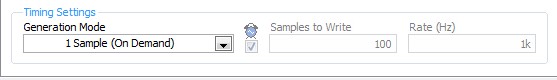
- Configure your analog output DAQ Assistant for output on the 9264 ao0, leave all default settings except for the generation Mode, you should change it to 1 sample (on request).
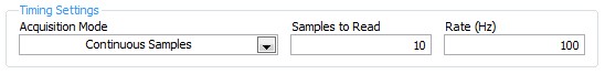
- Configure your analog input DAQ Assistant enter ai18, keep all the default settings again except for sync settings, which should resemble the following:
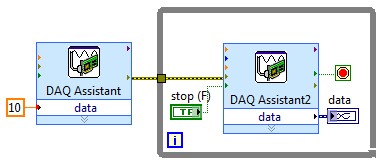
- Your drawing should look like this:
If you do this and you encounter problems with your sensor or its response after the datasheet (or at least the manufacturer and part number), and I'll look into it further.
- Configure your analog output DAQ Assistant for output on the 9264 ao0, leave all default settings except for the generation Mode, you should change it to 1 sample (on request).
-
Decent analog output of my Qosmio F20-154
I use my Qosmio as a Microsoft Media Center with my TV connected via VGA output. It gives me a pretty good image.
However, my TV does not support most of the modes of zoom for VGA; or it does for DVI or HDMI.
So I tried the image output via S-Video - which produces a shitty and unacceptable photo.
Unfortunately, Qosmio has no TV output, so I can't try it.
So, does anyone know of a piece of hardware that can be used to make the Qosmio to produce a decent analog output, such as TV-Out (antenna) or Composite?
Thanks in advance,
BrianAs far as I know you have only two options to send the video signal.
Qosmio F20 supports viga video and s-video ports.
So either you will use the video VGA (15-pin) port or output video super TV (S-Video) 4pol mini to connect the TV to the laptop...I have connected my laptop to the TV also using the s-video port and the photo quality is OK.
Please check you s-video cable and if possible test another in addition, I would recommend check some settings on the TV and s-video option
-
Analog output of access on fly buffer
Hi all
I have a X Series DAQ and made many analog inputs and output tasks. My question is that can an analog output buffer be accessed or modified during execution of the task? I have a redeclenchables analog output task, and I want to replace the buffer after a trigger is done before the next coming. Is this possible? Or put it in general, how can access us the buffer without re - create the task?
Any comment is welcome. Thank you.
Hi Skuo1008,
Which development environment you use to write this code? You mentioned a textual DAQmx function above in this post. Using LabWindows/CVI or ANSI C?
Take a look at these examples:
Generation of analog waveform with update with DAQmx output buffer
http://www.NI.com/example/25039/en/I have also attached to this answer
-
Simulate the analog output of arbitrary waveforms
Simulate it Arbitrary Waveform VI Express can be used to generate analog signals to the physical channels in analog output mode systems such as the NI 9263? I am trying to use the VI arbitrary signal generator to produce a signal used to excite the magnetic coils.
Why don't you just try and see what happens? As far as I know, it should work.
-
cFP-AO-200 analog output module (error-33180)!
Hello everyone
I use the CFP 1808 Bank as well as other such modules that HAVE 111 and enter I-110, I recently bought a Module AO-200 out of the currents of the order of 4-20 mA, I connected the module to the Bank and updated the device of the MAX Software, then I opened the Getting Started/Analog Output.vi leave examples in Labview to test 2011 map the VI returns an error with the code 33180 for me, I don't know what the problem is, but I tested the card with the MAX and wrote the values to it successfully.
Can someone tell me what is the problem with my VI
Thank you
I was able to reproduce your error. You must select 'All' in the Point IO Point field for this vi.
Maybe you are looking for
-
The numbers don't convert/export of files in Excel
Spin Numbers ' 08, Version 1.0.3 OS X Version 10.10.5, Yosemite I started by spending eight hours per person in total entry of data into a new file numbers "clean". Once completed, I needed to share this data with anyone who has only Excel. So I thou
-
I am sure that it is not displayed in the right shoelace, but put my avatar to my profile, everything seemed to be going well and it shows in my profile, but not here. Is there some time or p [ost conditions to appear? Perhaps Matt or Mark could help
-
8600 all-in-one... I can print tray enveolpes 2?
Cannot print envelopes from tray 2... Why not?
-
After installing Windows Update KB2446708 but still want to install each stop
The update of safety up-to-date security for Microsoft .NET Framework 4 on Windows XP, Windows Server 2003, Windows Vista, Windows 7, Windows Server 2008 x 86 (KB2446708) has been downloaded and installed, but Microsoft Update still asking me to inst
-
BlackBerry Z10 MP3 into a ringtone?
On my old curve, I had a ringtone that I brought out an MP3 of 20 seconds. Is it possible to recreate on a Z10? I always liked having my unique ringtone so that I didn't have to ask me if it was my phone or someone elsen can't go off.