acquire the voltage output of a channel of analog output current
I'm controlling a HV configuration rather sensitive analog output voltages. Is there an easy way to read the voltage level which is currently awarded by an analog output?
Hello
If you set your subVIs different voltages, you can be sure that the voltage you set in these screws are similar to tensions, you have to your output PIN. For example, you could write the value you give to the output in a variable and read this variable in you main VI.
Kind regards
Peter
Tags: NI Hardware
Similar Questions
-
Effect of the variation of the intensity of the LEDS on the Photodiode output current
Hello
I just started today to use the multisim and want to analyze how the intensity of the LED (LED_ir in multisim) is performing the Photodiode (TEMD1000 in multisim) output current. How to adjust the intensity of the LED and check the corresponding output on the photodetector on the oscilloscope.
I just built the attached LED design and don't know how to design the model for the foregoing analysis.
Could someone help me with this.
Thanks in advance.
Hello
Multisim works mainly with voltage and current, and whenever you need to represent the other phonominal naturual have a voltage or current source control. For a TEMD100, you must connect to a source of voltage up to ternimal light represents the input light.
-
The actual voltage of a physical channel of a DAQmx device display
Hello!
Quick question: is there a way to read the voltage of a physical channel of a DAQmx device, when there is no task that is running? I want this information after that I ran several tasks. It is important to know the real tension before you start the new task. Any ideas? Thank you!
Best regards
Michael
Hello Michael,
You are right.
The 'PCI-6110"and the «PCI-6711" have no internal channels.»
Could you please describe your exercise.
Why do you want to know your output voltage before you start a new task.
Best regards
Phanuel
-
PXIe6556 - how to change the voltage of output during the generation?
I would like to know if it is possible to change the voltage output (data lines) during the generation?
1. start the generation - Vout = 1V
2. change of output voltage without stopping the generation of Vout = 1.2V
3. change of voltage output of...
TKS
Try searching for "Advanced: incarceration strategy property attribute ' and ' voltage levels: data voltage range property" in aid of generator/analyzer of signals for the digital waveform installed with your driver. This should allow you to change the levels of tension on the fly. To use this attribute, you must have the latest driver HSDIO (2.0).
Is that what you are looking for? It is an advanced attribute, and most of the use cases should not dictate it you have been warned. I hope this helps!
-
How to acquire data collector output open.
the output data that comes from a single thread of the instrument without the signal ground of the instrument, IE, open collector output data. which is the least expensive and best hardware OR data collector output open?
Cross posted the LAVA:http://lavag.org/topic/16327-acquisition-of-open-collector-output-data/
As I said in the thread of the LAVA, there must be a reference to Earth somewhere. Now the question is that you try to measure the voltage output or the status of the output?
-
Error trying to read the voltage/current off the coast of Keithly 24xx. Help!
Hi all
I am trying to program (keithley 24xx) power to set and an output voltage for a certain period of time. I wrote cela all on labview and it works very well. I then added the ability to read and display the voltage output and current on my exit sign. ATER, I did, after the end of the time, run time, I'd get a beep and this error:
Keithley 24XX.lvlib:Error Query.vi
Reports of the instrument:
803, 'not allowed with OUTPUT.
0, "no error".------------------------------------
«"" "String of full appeal:»»"»
Keithley 24XX.lvlib:Error Query.vi
. VI 24XX.lvlib:Read (Multiple Points) Keithley
. VI 24XX.lvlib:Read (Single Point) Keithley
Basic_Operation.VI-------------------------------------
My guess is that the output turns off while reading is still ongoing, creating this error. I tried to find a way to fix this problem without success. Any ideas? I have attached a screencap of programming
Thank you!
You are the ' turn off before that can't read. When the time is true, the output is cut. Why do you even exit to activate it inside the loop? Make the first function outside the loop so that it is called after the loop stops.
-
the pci-6238 digital output current
Hello, I referred to the NI 6238/6239 specifications, but I've not seen this specification.
I wonder if the maximum output current is the same as the current (9mA) of entry?You can check this link for the information you need:
http://sine.NI.com/NIPs/CDs/view/p/lang/en/NID/202503 -
Hello
I'm doing a tension of 3-story ramp. One who goes from 0V to-1V can-1V to + 1V and finally wear the voltage of + 1V to 0V. The main feature is that I try to sync input only a channel for the median ramp. I get the expected input but my output voltage on the oscilloscope is not correct. The entry and exit and goes a box NI USB-6229. On the oscilloscope, you can consider the following issues:
1. There is a gap between the end of the 1st ramp and the beginning of the 2nd ramp
2. once the main finished once, ramp voltage immediately returned to-1V and again another ramp until it reaches 0V, then levels out for another short period of time
3. the cycle then repeated from the beginning, completely missing ramp 3
If all those who think they might help in any way, I would appreciate any input. If someone tries the attached program: I used these settings: entry rate = 1000; #data points = 200; DT = 0.0005
-Kyle Shiel
If you want to copy your ramp of 3 floors without any pause between steps, you must accumulate the entire waveform (all 3 steps concatenated) and write in your output task at once (similar format This example, but no need to start and you need to replace with your own generated table waveform).
I would just at the entrance to the beginning of the analog analog output task. You can use the DAQmx Trigger Start.Delay property if you want to wait for the 2nd phase begin to acquire, or you could simply acquire all 3 steps and analyze what you need.
Best regards
-
Controlled by the voltage analogue output
I missed more or less in my attempts to use the analog output features DAQmx. What I want to do is to create a program that will spend the next an analog input channel voltage analogue output channel. The basic idea is this: I am able the differential voltage in a simple temperature detection circuit. When tension crosses a threshold (for example, 2, 5V), analog output channel kicks on a constant 5V and stop to expel 5V when the tension of AI cross back on 2, 5V threshold. Is it still possible? I had trouble finding examples or starters to tide me over. Any suggestion would be appreciated. Write the code to acquire the signal of the AI is not a problem, I'm not sure of how to integrate the functionality of the ao.
Thank you.
Unfortunately I do not have libraries of Measurement Computing, so I really don't see what you're doing with your code, but I'll attach one VI example I did with DAQmx to get going you, and I hope that thinking in the right direction. I've added the analog out and digital output to show how each works. If you can make your code in DAQmx, please do and post and I can help you.
-
USB-6008 LABVIEW 8.2. SINGLE CHANNEL WITH DBL INPUT VOLTAGE OUTPUT COMPARISON
I AM WRITING A PROGRAM THAT USES A SIMPLE USB-6008 ANALOG INPUT CHANNEL. I WANT TO READ CONTINUOUSLY THE VOLTAGE FOR 60 SECONDS. I WANT TO COMPARE A TENSION FOR THE PREVIOUS OF THIS SAME CHANNEL VOLTAGE, MAINLY FOR THE PERIOD OF TIME MAX VOLTAGE GIVEN, THEN GET A FINAL VOLTAGE READING. THE OUTPUT OF THE VI IS A DBL. I WANT ONLY TWO TENSIONS OF EXPORT TO EXCEL. TO SAVE TIME, I KNOW HOW TO EXPORT. CAN SOMEONE HELP ME WITH THIS ONE.
VI needs an register shift related to the Max & Min function. The current value would be the entrance is and the entrance of x is the left shift register. The max value gets wired for the shift register to the right. Don't forget to initialize it. The output of the shift register is the max you would write and the value of the DAQmx Read out of the loop of wire will give you the last reading.
Your waiting for 45 seconds makes no sense since you said that you wanted to read continuously. You also said that you wanted to read 60 seconds and all this logic is missing. A simple function of time elapsed, it's all you need.
-
Update of unique value in the loop voltage output?
Hello
I'm trying to use the DAQmxWriteAnalogScalarF64 function to produce a voltage constant and regular say 3V. The program will be in a loop, and after each iteration, I would that the output voltage be increased to say 0.1V.
So, a shortened version of my program looks like this
float64 value = 3;
DAQmxCreateTask
DAQmxCreateVoltageChan
DAQmxWriteAnalogScalarF64 (TaskHandle taskHandle, bool32 autoStart, float64, float64 value, timeout, bool32 * reserved);
Loop
{
DAQmxStartTask
DAQmxStopTask
}
Now of course who does not help me update the output voltage after each loop. So I tried something like this:
Loop
{
DAQmxWriteAnalogScalarF64 (TaskHandle taskHandle, bool32 autoStart, float64, float64 value, timeout, bool32 * reserved);
DAQmxStartTask
DAQmxStopTask
value = value + 0.1;
}
My computer would crash when I try to run the program. I have to erase and create the task in each iteration too?
I try to avoid using the DAQmxWriteAnalogF64 function, because I need to use a sample clock in time, he and my sample clock is used for the other channel of analog output.
Thanks for any input.
Howard
aNItaB,
I tried to call the DAQmxWriteAnalogScalarF64 in a loop and freeze my computer completely and I have to restart it by pressing the Start button.
Then, I tried to use the DAQmxWriteAnalogF64 in a loop, specifying the output as an array of one element array, and then to update an element at the beginning of each loop. This seemed to have solved my problem for now without any computer breaks down.
A strange thing happened was when I took your suggestion and took the StartTask and StopTask out of the loop, the computer crash problem appeared again.
in any case, I think that my problem has been resolved, thank you very much for your responses timely and sincere help.
Howard
-
change the voltage with a different deadline for both channels
I have DC power which is having two output channels, each channel is capable of giving two different tension at a time. I want to change the voltage for channels with two differnet time. ex: voltage channel 1 will change each time 2mins and canal2 tension will change to each period of 5 minutes of time. so please give me the suggestion for this problem thanks in advance.
Maybe like this...
-
Hello
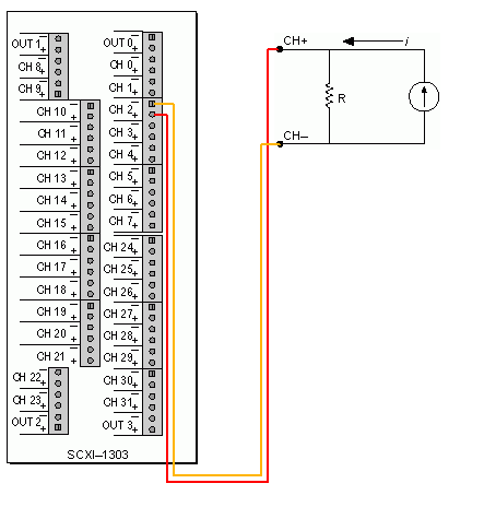
I'm trying to use two sensors of moisture Omega HX85BA and experience two CFI mass flowmeters in current loop. Humidity sensors have three outputs 0 - 10V, while flow meters have two outputs 4-20 Ma. Can I have all four sensors to wire to the same block of connection SCXI-1303 and read all the signals in the same VI? the block is connected to an SCXI 1102 b card and a 6052E DAQ of NI PCI card.
Thanks in advance!
Hello BBalmforth,
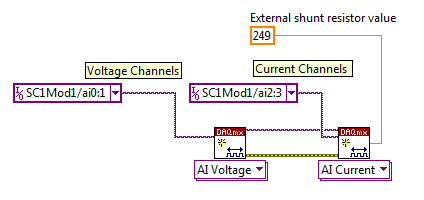
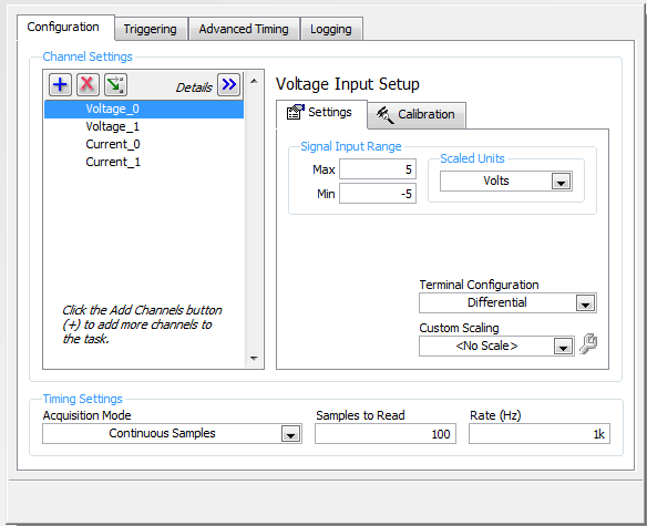
Yes it can. Although you will need external resistances (I recommend resistors precision for better accuracy) for current signals. The SCXI 1102 b is indirectly measuring the current by measuring the voltage drop across the resistance. The table below describes the current diagram and how it will seek in LabVIEW and DAQ assistant.
Wiring diagram
LabVIEW
DAQ Assistant
Kind regards
Izzy O.
Technical sales engineer
National Instruments
NI.com/support
-
Acquire the values only when the digital output is high.
Hello
I work with test of transistor, whose door is controlled by the digital release of USB6289, related to BNC2120.
Test plan:
Door 1.transistor is enabled for 5seconds, with P0.0 for example
2. then, everything remains off for 1secondes.
3.p0.1 is used as digital output to activate the circuit passing him curent through in the opposite direction, P0.1 goes high for 3 seconds, PS: Gate is off.
4. the same cycle repeats again.
My question is to store values to the output of the transistor when P0.0 and P0.1 goes high, and these values should not change until my digital outputs respective again go high.
I can access transistor by continiously read out my power supply values.
and in the State off I want to read AI0 because at that time, my power supply is off, so that I can activate the circuit to pass the current in the opposite direction.
Again, my question is to gain the output through power value when P0.0 is high and store them until the transistor turns on.
and even for P0.1, acquire the value of output through AI0, when P0.1 is high and store it until it goes high again.
Hopefully, I'm able to explain my problem clearly.
Please help me.
Concerning
Anurag
Think about what States (object:statemachine and determine when to use sequence Structures) do you want from t0... t(n-1), IF DAQmx generates outputs and/or inputs are absorbed and what needs to happen (event timed out), before move you on to the next 'State '.
type def 'enum' with your different States:
- initialize
- wait (the user initializes times (sec) set for States, or whatever and presses button 'Start')
- T0 (generate DigOutputs, store acquired data AnalogOutput (string output number) the register shift, before moving to the next State > user 'set time' must elapse (Note: the wait function allows you to control the rate of execution of loop and allow the CPU to respond to external events and system tasks and avoid using wait functions at the same time an operation of software...))
- ...
- t(n-1) if ' end (made requirement) "> goto 'stop', ' another (not requirement not)" > goto regardless of 'State '.
- stop
- write a text file of data (string).
-
How do switch you between multiple channels to indicate which channel to acquire the data from?
I'm trying to builld a VI where I can have an option to enable or DISABLE multiple channels depending on the modules plugged into the chassis and then acquires the data of the channels which are turned on and where other acquisition parameters do not change. Is there any specific/switch where can I do this? Please answer as soon as possible. Its quite urgent. Thank you
You use DAQmx? To change the assignment of the data acquisition channels, you must close the currently open session and then create a new session with the new channel definition. So the order of execution:
Create task or virtual channel - read - clear task of triggering and synchronization of the configuration - set new channel list and to create a task - read - clear task, etc...
Maybe you are looking for
-
Administrator account has been disabled and cannot connect at ALL.
I own a 'HP G71-340US Notebook running Windows 7"and I'm trying to restore my computer completely (for delete). Then at some point when I turned on the computer a few days ago, it took me in the Recovery Manager, I couldn't do anything. I try to rest
-
Tecra A10 - Firewire chipset that is used?
Hello everyone, I plan to buy a tecra A10, but I have a question on the left.For my FireWire cards that I use, I need to know what kind of brand FireWire chipset does build to the A10. Does someone knows or can verify this for me?It is visible in 'De
-
1074395995 error in WriteJPEGFile IMAQ
No idea why this is happening? Why this error occurs?
-
Reading codes ascii serial port and their trace
Hello I am trying to build a VI that reads data (ascii values) of the serial port. I am trying to build a Phonocardiogram wireless. I have a microphone that acquires the heart sounds. These signals is amplified and sent to an A/D converter to digitiz
-
Original title: the awduu36e.sys file is not found. After a repair of windows XP SP3, I receive, at startup, the message "the file awduu36e.sys is not found. Press a key to continue"- I can't press a key because the keyboard is not recognized or acti