Variance of 20 samples at a time...
Hello
I asked a similar question before, but now the functional requirements have changed so I need to change the vi...
This vi must calculate the gap data in 'chunks' of 20 points (or whatever the user wants), if the gap is greater than the threshold value it should start to calculate the difference between data points in the "block". Once he meets a difference that is greater than the variance is allowed (the threshold), what time is assigned and adds 1 to the loop counter. In the end, a total counter is compared with the threshold to see if he could not or not and that he must write time entries in a .txt file.
For the moment, I see a problem - the variance is always equal to 0, and I don't know why.
I appreciate any input about the obvious and any other problem you see.
Thank you
Tags: NI Software
Similar Questions
-
Use an encoder to establish and sampling in discrete time
I can't really control what DAQmx subs to use and how to configure. It should be a simple task, but not for a beginner like me. WARNING: I spent hours reading the help files, knowledge base articles and research forum and there is nothing in them that makes sense to me. Details of the operation are in the diag of block. Please take a look and see if you can guide me. THX.
BTW... Using panels of MAX test I checked the wiring, operation and configuration of my sensors. With the attached vi, pgm does not signal departure but initiated each time the first 'A' pulse arrives. This checked because the encoder can measure data without ever passing the pulse "Z".
Thanks Mike. I got this example and it is one that I had already downloaded. It does not work. After the start pulse, it reads all the samples in the sample clock frequency, not on the edges of the reference trigger pulses. The example is wrong. So I did what I normally use in these cases... wandering banging my head against the wall until something gives.
Solution. Set the example of wiring in the source of reference trigger control in the source of the input clock as well as in the relaxation of reference under vi (this thread already exists). He now works as it is supposed to. Hard learning of examples when the examples are wrong. Here is the solution where all els tries to emulate this example.
-
DAC single sample write response time
I use the acquisition of data USB-6259. I wrote a simple loop to write permanently a single sample of an output to check the next time of turing analog voltage pos & neg. I have the 'writing analog DBL 1Chan 1Samp' connected to a 'multiply by neg 1 "in a loop. I run the application, and it seems that the response time is about 3msec between +/-. It's far too slow for my application. My application requires constantly reading and setting of the tensions. I get a high sampling frequency if I'm out a waveform. However, I didn't go out a waveform. I went out a voltage in response to a voltage reading. Is it possible to have a shorter response time? Is there another method (using C?) to improve response times?
Erik,
Windows is deterministic up to 1 ms, so there is no way we could get this application in the field of speed you need with the current hardware. I think that you could implement this with an FPGA, and we have many options available.
-
External sample clock change takes a lot of time on the SMU-5186
Hello
I use the external Lv - niScope EX Clocking.vi example to define SMU-5186 using an external sample clock. However, it takes a long time, 5-6 minutes, before I can get the first block of data acquisition.
Then I run the example 'niScope EX Acquisition.vi Configured' to switch to dashboard clock. There are also 5 to 6 minutes on the first acquisition.
I think maybe the SMU-5186 made some calibration when I change the source of the clock.
Anyway is to ignore the calibration? Or make it faster?
Thank you very much
Yiming
Yiming,
Delays in acquisition are caused by calibration routines that must be performed on the engine to sample (ADC) every time that changes sampling rate. This ensures our justified precision specifications.
I don't know if you've noticed also calibration of Power-Up, which will take 5-10 minutes to complete when the unit is turned on. This is mentioned in our specifications at page 18:
http://www.NI.com/PDF/manuals/373257b.PDF#page=18
I hope this helps.
Nathan
-
Hello world. I need to trace the variable amplitudes compared to the timestamp (date and time), but the time intervals between samples are not equidistant. In my area, this is called trend plot. I'm surprised that Labview does not a vi to do this. The only solution that I found so far is to save the data in an Excel file and open this chart in Excel because it has the ability to trace what that this is against what whatsoever is not limited to something as even spaced samples. How to achieve this is Labview? A graph of waveform vi would be perfect if it was not by the fact that it works with even spaced samples.
Thank you.
Paulo Siqueira
Your requirement is directly possible with LabVIEW.
You can spend time to understand the difference between 'Chart', 'Graph' and "Graph XY".
VI attached is drawing samples of unequal time.
Hint:-right click on the 'XY' graph-> properties-> display-> 'Axis of X' = absolute time Format
Kind regards
Yogesh Redemptor
-
given high-frequency sampling one at a time
Hello
I'm using LabView 2011 for resistance measurements. The express vi DAQ assistant is placed in a while loop and it acquires 1 sample (on request).
Each sample is acquired, it is compared to a set point. If the resistance value is greater than the set value, a task is executed. If this is not the case, no action is taken.
Now, I would like to increase the frequency of acquisition of say 5 kHz. As before, I wish the DAQ to give each value because it is acquired and compare it with the desired value. However, only one point acquistion is limited by the speed of the while loop (which does not exceed a few Hz per second when I use the software-timer.) If I use 'continuous samples' at 5 kHz, data acquisition does not give these samples one at a time. It seems to acquire until the buffer is full and then released several samples at a time. It is therefore impossible to compare with the set value.
Is it possible to get data at a high frequency and do compare to the set value, one at a time?
The code is simple enough to do this.
But the problem, it all comes down to how fast all of the other code in the loop takes to run.
The first problem is that you use the DAQ Assistant, which provides a lot of extra load in the loop, especially if you don't set it up properly. (And we can't say because no code is set to look at us.
You should try a real code DAQmx where launch you acquisition continuous samples before the loop, acquire exactly 1 sample in the loop. Then close the DAQmx task once the loop ends. See if keeps.
Why do you need to do this? Note that all instant Windows might decide to fly a second or two and go and do something else like a virus check. If you need at that moment (how exactly do you need that?), then Windows is not the right system for this run.
-
I'm new to myRIO and use it to measure sine wave (0V to 5V) of up to 10 Hz 20 KHz. I also quickly transformed of Fourier (FFT) of the signal measured in real time.
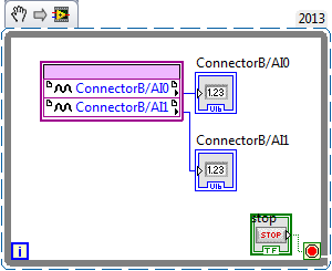
Sideways FPGA of things, I try to keep things pretty simple, just read 2 channels of AI (connector B: AI0 and AI1), therefore potentially able to read each HAVE 250 kech. / s (as the unit has a capacity of 500kS/s). Does that mean this program gets a two analog inputs data exactly every 4 microsecond? If this is not the case, how can I make sure that the data is acquired through a fixed sampling rate?
I realized that we can add to the FFT in FPGA function, but I wanted to manipulte the acquired data of analog inputs before it is sent to the FFT, which I don't know how to do now. Can someone explain me how do the arithmetic data (muliplication, division and so) on the acquired data and analog inputs to reducde the 12-bit resolution 10-bit to program FPGAS.
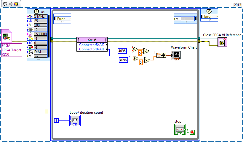
Later, I created a myRIO program to read analog data 2 FPGA program which continues to turn in timed loop. In the program myRIO, the timed loop is configured to 1 MHz clock source type by a delay of 25 microseconds.
This configuration means that the loop runs exactly every 25 microsecond?
When I set up the less than 10 micro second time, myRIO has stopped working. Why is it so?
Is it because myRIO cannot run as fast as FPGA?
It is advisable to make the FFT of myRIO side analog data or FPGA?
When I tried to do FFT using the power spectrum of myRIO side, he asked for waveform data. What I acquire is data analog. How can I convert in waveform data?
If I read in the forum for help, I couldn't have the full answer to my doubts
Discussions at the Forum I did reference:
A lot of good questions here, I will try to answer as much as I can so as to offer a bit of advice.
First of all, if you are looking to acquire data at a very specific rate on the FPGA, you'll want to use the Timer VI. You are also going to use a FIFO of DMA to transfer data of FPGA in real time. A node read-write using as you do now means you'll run out of samples, or read the sample even several times. The link below is a very good tutorial on how to do what I described above.
http://www.NI.com/Tutorial/4534/en/
Later, I created a myRIO program to read analog data 2 FPGA program which continues to turn in timed loop. In the program myRIO, the timed loop is configured to 1 MHz clock source type by a delay of 25 microseconds.
This configuration means that the loop runs exactly every 25 microsecond?
When I set up the less than 10 micro second time, myRIO has stopped working. Why is it so?
Is it because myRIO cannot run as fast as FPGA?
In general, you should not run a timed loop much faster than 1 kHz. Using timed inside loop knots, you can monitor the real rate of loop during execution to see if f you meet your needs of the moment.
The portion of your myRIO RT is slower than an FPGA in the sense where it cannot manage the rates of lines 40 MHz (he makes up for it by being able to work with much better pictures) and it is important to remember that it is just a computer. The advantage of a real-time operating system, is that you have more control on the Scheduler, not that he is faster (less jitter, not faster code). There is more good reading below.
http://www.NI.com/white-paper/3938/en/
It is advisable to make the FFT of myRIO side analog data or FPGA?
When I tried to do FFT using the power spectrum of myRIO side, he asked for waveform data. What I acquire is data analog. How can I convert in waveform data?
I would say that it is generally advisable to treat your FFT on the side FPGA as long as you have the resources available, but for many applications probably little matter ultimately.
-
Writing data to extend the acquisition of data for the sampling rate high file
These are the tasks that I have to do to take noise measurements:
(1) take continuous data to USB 6281 Office, in a sample of 500 k (50 k samples at a time) rate.
(2) save data continuously for 3 to 6 hours in any file (any format is OK but I need to save in a series of files rather than the single file). I want to start writing again file after every 2 min.
I enclose my VI and pictures of my setup of the task. I can measure and write data to the file continuously for 15 minutes. After that, I see these errors:
(1) acquisition of equipment can't keep up with the software (something like that, also with a proposal to increase the size of the buffer...)
(2) memory is full.
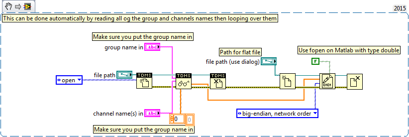
Please help make my VI effective and correct. I suggest to remove him "write in the action file" loop of consumption because it takes a long time to open and close a file in a loop. You can suggest me to open the file outside the loop and write inside the loop. But I want to save my data in the new file, after every 2 min or some samples. If this can be done efficiently without using Scripture in the measurement file then please let me know.
Thank you in advance.
This example here is for a single file and a channel, you should be able to loop over that automatically. The background commentary should be the name of the channel, no group namede the name of the channel in the control.
-
I am using a cDAQ 9172 with modules NI 9219, NI 9264 and three NI 9211. I'm looking to acquire signals out of the acquisition of data within a loop under continuous sampling. My program works fine if I set the number of samples to read 1-2 Hz, but I need to go faster than that. If I change the sampling rate, the loop is executed at this speed but sensors still read only in samples at 2 Hz and then duplicating over and over again. I was wondering if it was possible to read on 1 sample at the time of the acquisition of data at a faster rate. I know that the frequency of sampling on the sensors and data acquisition are much higher than that. 1 sample at the time of the Board of Directors has the limitatioins of being only able to run at 2 Hz? Please let me know
Thank you
Craig
Hi Craig,.
I don't know exactly what you describe. Are you feeding the DAQmx Read output in an express VI? Or are you using the express VI DAQ Assistant for the analog input task?
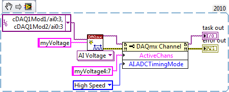
If you use the DAQ Assistant, you can set the ADC synchronization mode without changing your code:

If not, use the 'Active channels (if subset)' property to control the subset of channels on which your VI defines AI. ADCTimingMode.
For example, the following code snippet creates 8 virtual channels named myVoltage0 by myVoltage7 and sets HAVE them. ADCTimingMode on myVoltage4 of virtual channels through myVoltage7. These are in the cDAQ1Mod2/ai0 physical channels via cDAQ1Mod2/ai3:
If you leave off of the entry "name" on the string to create VI, then the virtual channel names are the same as the names of physical channel, so it's the equivalent:
And by the way, a right-click on the property and selecting "create > Constant ' context menu saves you from having to hardcode a number like 14712.
Brad
-
PXI-4071 sampling too slow when using a hardware trigger
We use 3 PXI - 4071 s in parallel to measure with accuracy of high voltages. The program is written using LabVIEW 8.5.1.
An additional test condition has been added which requires the use of a quadrature decoder and the synchronous DMM.
We thought it would be simple, using backplane trigger 0.
However, something odd happens.
With a low-cut VI that uses a single DMM, we get 100 microseconds time to sample running with internal triggers. However, if the overall relaxation or trigger of the sample is set to TTL0, the sample time becomes so 5.1 milliseconds. It seems very strange that even just definition of overall relaxation, expected to affect only the time of the first sample, not the time between samples, has that effect. The plug for the DMM also said, that the maximum trigger rate is of 6 kHz.
We have confirmed this reported sample time is independent of the speed of the clock actually connected to TTL0. If the clock is faster, it gets the reported sample time. If it's slower, the samples occur on the edges of the clock.
Does anyone know if there is a parameter that has a default that changes based on the source of command and can be changed to work around this problem, you?
I found the solution to this.
Over time the value-1, the DMM uses a short value (less than 100 US) to set hour when, in modes triggered internally. However, he used much longer (about 5 ms) when the value - 1 and with the help of a hardware trigger.
If the running-in is set to 1e-5, i.e. 10 microseconds, "the estimate" returned for conversion period goes from 5.1 ms 100, we and conversions actually occur at a rate set when clocked with trig 0-5 kHz
-
Hello
I'm trying to measure the time between 2 datapoints.
During the data acquisition begins the time must be saved and when the signal reaches 90% of it is max.
These 2 times then extracts itself and then you have the elapsed time.
But I'm not sure how to proceed... I thought with dishes sequences.You capture a signal at all times? What is your sampling rate?
What you need to do first to get the signal. You can find the maximum value with Array Max & Min function. Calculate your 90% (0.9 * Max). Search the data until your get the 90% or greater. Download this issue of sampling. Your time is so number of samples at the helm of the 90% divided by the sampling rate (samples per second).
-
The irregular sample in PDM data storage
I have a request where I capture data (DAQmx) waveform of several cards of analog interface as I am data capture irregularly timed to an Ethernet network.
The irregular data comes in as an array of values from layer to about 250 Hz with each sample set precisely time-stamped. Synchronization between the sample is so important so that these data cannot be stored as a waveform. It should be kept as an array of pairs of channels/timestamp or timestamp value / (array of string values).
DAQmx data, of course, are given waveform with only the timestamp and necessary delta departure.
Then, there are suggestions of popular community (recommended ways) of:
- Set a TDMS file for irregular data
- Create a single TDMS file for irregular data and DAQmx waveform data in a common format
Thank you
XL600
In this case I used my first string be 'Time' and it is stored as an array of timestamps, where every hour is a value on this index to another channel. There is a function in the LabVIEW on waveform palette which will take a waveform and generate all the times associated with the values Y.
Oh and so I usually have a new group for each sampling frequency, then you might have DAQ as a group at a rate that is regular, and there a Time column, and another group might be called the series that has a column of data and time to a non-regular rate.
-
DaqMX wait the next sample causing slow down Clock.vi
Hello
I have a question about the proper use of DaqMX wait for next sample clock.
I read channels analog voltage on a map or pcie-6259.
I would like to read as soon as possible make your comments between each of these points of single data points.
I wish I had an error generated if I miss a data point.
From reading the forums, I've gathered that the best way to do it is using the Timed Single Point material.
A simplified program that I use to test this is attached.
If I remove the DaqMX wait for next sample Clock.vi, my program seems to work.
I added a counter to check the total time is as expected.
For example, the program seems to work at the speed appropriate for 120.
However, without that vi, it seems that the program does not generate a warning if I missed a sample.
So I thought that the next sample clock waiting vi could be used to determine if a single data point has been missed using the output "is late."
However, when I add inside as shown in the joint, the program seems to slow down considerably.
At high rates as 120000, I get the error:-209802
14kHz is the approximate maximum rate before you start to make mistakes.
My question is: is this the right way to check a missed sample? I don't understand why the wait next sample Clock.vi is originally a slow down. Without this vi, the program does just what I want except that I do not have strict error control.
My confusion may be based on a lack of understanding of real-time systems. I don't think I do 'real time' as I run on an ordinary pc, so maybe I use some features that I wouldn't.
Thank you
Mike
Mike,
You should be able to read to return delays errors and warnings by setting the DAQmx real-time-> ReportMissedSamp property. I think that if you enable this, you will see errors or warnings (according to the DAQmx real-time-> ConvertLateErrorsToWarnings) in the case where you use read-only. I'm a little surprised that you have measured your application works at 120 kHz without waiting for next sample clock (WFNSC), although I'm not surprised that it would be significantly faster. I think if you call read-only, you'll read the last sample available regardless of whether you would of missed samples or not. When you call WFNSC, DAQmx will always wait for the next, if you are late or not sample clock. In this case, you will wait an additional sample clock that is not the case in read-only. Once again, I expect that, in both cases, your loop would not go to 120 kHz.
Features real-time DAQmx (hardware Timed Single Point - HWTSP) are a set of features that are optimized for a one-time operation, but also a mechanism to provide feedback as to if a request is following the acquisition. There is nothing inherently wrong with using this feature on a non real-time OS. However, planner of a non real-time OS is not going to be deterministic. This means that your app 'real time' may be interrupted for a period not confined while the BONE died in the service of other applications or everything he needs to do. DAQmx will always tell you if your application is to follow, but can do nothing to guarantee that this will happen. Thus, your request * must * tolerant bet of this type of interruption.
There are a few things to consider. If it is important that you perform the action at a given rate, then you should consider using a real-time operating system, or even with an FPGA based approach. If it is not essential to your system, you might consider using is HWTSP, where you do not declare lack samples (DAQmx simply give you the most recent example), or you could avoid HW timing all together and just use HAVE request to acquire a sample at a time. What is appropriate depends on the requirements of your application.
Hope that helps,
Dan
-
9239 number of samples compared to rates
Hi all
I'm running a VI for the 9239.
In it, I updated the sample clcok 2048.
I then put the number of samples to 20480, IE rotate for 10 seconds.
However, instead of the final point to be measured to 10s it measure to the 9.82992
If it is set to 2048 samples the final time is 0.98256
I realize that say, if I had a rate of 5 samples per second and one took five samples, I'd get the next 0,.2,.4,.6.8
But if I had to wear it to 10 samples, I'd get
0,.2,.4,.6,.8, 1, 1.2, 1.3, 1.4, 1.6, 1.8
The important point here is that the offset remains the same
In addition 1-1/2048 =.99951171875 pas.98256.
Anyone know what is happening here?
Sean
Add to that,
You made a very good point about the first sample being taken at t = 0. Accounting for this, we get:
20480 samples
(20480 / 2083.33333) * (1-1/20480) = 9.82992
2048 samples
(2048 / 2083.33333) * (1-1/2048) = 0.98256
What exactly gives the number you reported.
Best regards
-
On a NOR-6363: how many digital samples can be acquired at once?
Hello
I use a NOR-6363 with meter 3 configured for pulse generation finished.
I created a digital input channel to acquire digital values (on P0.16 and P0.17) with counter3 as the sample clock.
The idea is to acquire a finite number of digital samples (even as the number of finished pulses generated on counter3).
Currently, I'm trying to figure out if I can get about 1000 samples (requirement of my request).
The data sheet indicates that the FIFO size for a digital input is 255. Is this to say that I can not acquire more than 255 samples at a time?
I tried to use high values up to 1000 but no error occurs.
Is this to say that the reading of values will be correct?
Or im guessing it might be a circular FIFO that overlooks the same values reading values of more than 255.
Should I worry about this limit of 255 at all?
Thank you
Since no one answered this yet and I posted my question there are times, I'll take a stab at a helping hand.
The FIFO on the digital input is the place on board where the samples will be kept until their transfer on the bus in the RAM. So, the question becomes what controls when these samples are pushed to the RAM. If I remember correctly, this card has 8 DMA 1 channel who will control when these samples are transferred on the bus. I don't think there is a way to control when the DMA channel completes his transfer, but the first transfer is likely before you fill up the first 255 samples. DMA transfers will continue to occur until all samples have been transferred to the PC RAM.
Once some or all samples have been transferred to the bus and reside on PC RAM, you call then call DAQmx read. Then, the samples are in your Application development environment (ADE) RAM, if you use them in your program. You have 3 separate storage locations: FIFO on board, PC memory, memory of the ADE.
You shouldn't have to worry about the limit of 255. Maybe if you were doing a very fast acquisition, this could be a factor...
Kind regards
Eric

Maybe you are looking for
-
Hello, I had the bad virus and I'm trying to restore your my computer to factory settings. When I restart the computer and press F11, f11 does not work.
-
Someone asked saying me that they are from technical support and my computer has a serious infection. They wanted me to compare my CLSid. Microsoft never does the calls of this nature?
-
I have a problem of access to (most) programs on the desktop, when I double click on an icon I get the window "open with." After tinkering with the computer, I found that the file "rundll32.exe" showed as an icon of paper instead of the icon '.exe '
-
An urgent need to change the code PIN, don't want to factory reset
Hi all A few weeks ago, I accidentally dropped my Xperia Z3 Compact on the ground. The damage was not serious, apart from a few scratches on the screen, at least, I thought. It turns out that the damage was much more than just some scratches: a few h
-
Hello Where I work, we have a phone call, saving application that creates records of calls as .wav files. Before placing each record in long-term storage, the application creates a copy of the file (which is smaller) MP3 and then made a calculation o