vertical scale
Hi, how to create a vertical scale for an altimeter or a speedometer whith LabView?
Fred of tanks
Tags: NI Software
Similar Questions
-
vertical scale 5152, set up the time
I use a pxi-5152 in a pxi-1033 chassis.
I want to play a trick and change the vertical scale between my measurements to increase the dynamic range of a signal that I'm scanning. I made a loop and changed the vertical scale property node after each measurement. It works, but when I timed it the loop, she seems to take 80 ms. I need to do in less than 10 milliseconds.
Is it still possible? I see the real time it takes for the scale change or there at - it something to speed up?
I also have access to a PXI real-time with the same card. Could only accelerate things or is the digitized the limiting on the change of scale factor?
Thanks for any help
-Rich
Hi rich,
I see the real time it takes for the scale change or there at - it something to speed up?
You probably see the effect of the two. There may be something of software that you can do to improve it, but there's always a material limitation when you do this kind of operation. Switching of the means of vertical lines change from one type of mitigation to another path. This means there is sedimentation time involved (electronic and mechanical, with obviously dominant mechanics). The main element in the run-in will probably be the relays that are reversed. There must be a minimum period after the passage of a relay to ensure the data read by the digitizer are correct / valid.
Since you know your signal is going in a direction (descending), then you may be able to improve somewhat by calling the property to write the new range, and then commit node & initiating in a loop which contains a minimum transformation (possibly using queues in LabVIEW to transfer the data in another loop of treatment). If you need treatment in the loop, you must perform the treatment after niScope commit but before launch niScope. This will allow the digitizer begin to settle in the new configuration, and you have to wait less time when you're ready to call to initiate.
I also have access to a PXI real-time with the same card. Could only accelerate things or is the digitized the limiting on the change of scale factor?
Real-time processing ensures determinism, it does not necessarily speed up the application. Determinism and defining a specific priority for calculations of software can help speed upward the software that you are running, the interface of low-level PCI/PXI bus driver with the instrument probably will not change radically. You can certainly try though and let us know what you measure.
I can understand if it is a fundamental issue, because normally people are not change the range of vertical entry on the fly, but if there is a way around it, it will avoid the need for me to put an amplifier with variable gain on the front-end server or buy a digitizer with more bits.
This isn't a perfect suggestion, but just a thought: If you have several scanners at your disposal, you might try setting each to a fixed vertical range and split the signal among them. TClk, you can synchronize these devices together to make sure your data points are sampled at the same time, and then introduce delays in the initial on each digitizer trigger so that they take account of the waveform in a cascade mode. For example,.
Digitizer #1, attached to the greater vertical reach, would have no time limit from the time wherever the trigger is received.
#2 digitizer, set at a smaller vertical range has a fixed period of (10ms?)
Digitizer #3, value the smaller Beach, has a fixed time (20ms?).
Otherwise, if you have assistance with the OR, you could try to call a technical sales engineer to discuss other possible options.
-Andrew
-
Hi, I oscilloscope agilent DSO7012B, I started DEVELLOPING this device in labview interface, but I have a big problem on the vertical scale, I can't settle between vertical scale and mitigation of the probe to have a vertical scale of 10mV to 5V/div @ x 1 probe 100mV to 50 v/div @ x 1 probe 10 v to 500 v/div @ x 100 probe 10V to 5000V/div @ x 1000 probe 100V to 50000V/div @ x 10000 probe 200mV 100V/div @ 20:1
If I understand correctly, you'll have to do some arithmetic make use of graphical property nodes. As I said, the scope does not accept orders volts / div. You simply specify a maximum voltage personally, I think it's a better option for the user. In any case, if you set the size of the chart, you can use the button for to scale the chart. Say you have 10 divisions and 1 volt per division. The actual parameter that you pass to the function of scope of configuration is then 1 5 times (the number of positive divisions. You can also cheat a bit and set the scope to its physical button volts/div and do a reading of its value range. The button can be connected to an instruction box with the values of the scale. Just don't use a knob for dbl. Use it as a whole with text labels.
-
That really means the vertical range? And the gain factor?
The NI PXI-5102 digitizer: that means vertical range really means, it is the range of voltage of the signal to be measured or the signal to the ADC input terminal?
How to control the gain of the digitizer? And what are the factors that can affect the gain?
The portrait is located between the valid entries range of the digitizer on that channel. If you set the interval to a value that is not valid, it will be converted to the next highest value. This is the way you control the gain of the digitizer. It is easier to define the vertical range on the maximum expected range of your input signal and allow the driver to NO-SCOPE compel the beach to the next highest value. This allows you to use your code effectively with more than one type of digitizer (5102 and 5112). For example, you know that your input signal has a range of 3 v (+/-1.5V). Set the vertical range at 3. OR-SCOPE that will force to 10V, the next beach valid more high for the 5102. You can find the valid vertical beaches for your device in the folder of Documentation OR-SCOPE in your Start menu or online.
Mitigation on your scope probe will affect the vertical range of the device. If you have a 10 X probe and defined the vertical range to 10, the actual vertical scale will be 1. You can have NO-SCOPE figure that out for you by setting the mitigation of the probe with vertical Configuration.
More information on the routes of entry, and gains are available in NO-SCOPE help about using vertical configuration.
-
I try to use an oscilloscope to 3034B TDS to take autonomous action. I'm using LabView 8.0 and I downloaded the correct drivers.
From now on, I can control the oscilloscope settings and take action. The problem is that I can't find a vi that controls the horizontal scale of the oscilloscope.
The vi channel configuration has the vertical scale.
Any help is appreciated.
Thank you
Use configure Acquisition Record. It wouldn't be a channel config since the horizontal synchronization applies to all channels.
Assuming you are using the style of the project pilot, there are examples in the example - material input and output finder > instrument Drivers > LabVUIEW Plug-and-Play. You should have seen the function above in a couple of them.
-
Backup file that it changes more small PDF type file size point and vertical scaling
I have an Adobe Illustrator CS6 document with body copy using 6.5 PT. Neue Helvetica LT STD - Bold Condensed & Light Condensed.
After you save the file as a PDF in Illustrator by using the [smallest file size] parameter, closing and opening of the newly saved in Illustrator - PDF text of 6.5 PT is now 5.53 PT with a vertical scaling of 117.65%.
This PDF file is for purposes of customer review - on the screen or laser print - not for reproduction. We try to keep the file size as small as possible to make the download and attachments manageable.
In this case, my client opens the PDF file in Illustrator to check the sizes of text for legal and regulatory purposes.
If I record the same Illustrator file to PDF using other parameters as [high quality Print], the size of the text is unchanged.
I was able to repeat the question using Helvetica LT Std instead of Helvetica Neue LT Std.
I have attached a few screenshots for reference.
Screenshot Source Illustrator

Acrobat PDF screenshot

I found this old net 2011 where someone had the same problem - but has never been resolved:
http://forums.Adobe.com/thread/915047
well I was able to recreate the issue with the exact same font and numbers - matched both of your screenshots.
To summarize "preserve Illustrator editing capabilities.
He seems less to do with the "smallest file size" preset as it does with the box "preserve Illustrator editing capabilities". If you click on that even with the smallest size of selected file, you should not have the question - BUT you will have a much larger file (especially if there is high-resolution images).
Now, with the default size"small file" read PDF in Acrobat it was always pulling up to 6.5 not reducing the size. Opening the rear PDF file in AI causes problems. I trying to reinterpret the changes made to the police (follow-up etc.) but since "Keep editing functions Illustraor" is not checked, it is basically guessing as to what he must do to match like the appearance of the font in the PDF file. Yes police is smaller but the extra vertical scale of the changes that it is visually a game tight.
So if you save a PDF file without editing functions of checked you will have some funky things happen if you open this PDF back in artificial intelligence ('high quality' preset editing a checked).
If your client wants to open in artificial intelligence, you will have to give them a larger file with Ia editing capabilities. To try a free Dropbox account or Hightail account.
-
How can I read scale boxes paragraph?
Hello
I'm reading some text boxes values in photoshop for an export script I'm working on. I came across a problem that I can not understand, I hope it's just a small thing.
When reading the text of paragraph values, there are some cases where the values will come out wrong. For example:
I have a layer with the text of the paragraph by indicating that paragraph (text box) size is 400 px by 400 px and the font size is 60 points.
If I am running a script similar to this:
[code]
Get the text layer and save ir to a variable named layer.
If (layer.textItem.kind is TextType.PARAGRAPHTEXT)
{
Log ("Width:"+ layer.textItem.width.as ('px') ");
Log ("size:" + layer.textItem.height.as ('px'));
Newspaper ("the font size:" + layer.textItem.size.as ('pt'));
}
[/ code]
My output reads as follows:
[code]
Width: 200
Height: 200
Font size: 30
[/ code]
Which is obviously false, because all values are half of what they should be. I have other layers of text in the same file that print the correct values!
After trying a lot of different things, I thought a way to reproduce the error, but not a way to remedy, it is here:
-Create a new layer of paragraph text by clicking and drag using the text tool, make the text box about 200 px 200 px
-Type text in the box of
-Select the text and make it 30pt size
-Complete text
-Make sure that the text layer is selected
-Press command-t (ctrl + t in windows)
-In the free transformation parameters, manually type 200% for both with and height
-Accept changes of transformation
-Use the text tool, and then select the text of the layer
At this point, you will notice that the text box reports its size as 400 px by 400 px and font size says pt 60, far, everything is logical, the question arises when you look at the info tab, scale is reported as being 200% for width and height and if I use the previous script printed sizes are the origin of the text box sizes : 200 px 200 px and 30 pt for the font size.
At the beginning I have but it would be easier to use the horizontalScale TextItem as and verticalScale properties as well:
[code]
Log (' vertical scale: "+ layer.textItem.verticalScale");
Log ("horizontal scale:"+ layer.textItem.horizontalScale ");
[/ code]
But even though we know that the scale is 200% the result reads:
[code]
Vertical scale: 100
Horizontal scale: 100
[/ code]
Unfortunately that I have no control over how content is created, so I can't avoid using the tool of transformation on the text of paragraph, or of any text (this problem also affects the font size in single line text layers). So I need to find a reliable way to either read the correct values of the text or to read the scale that affects the text in my diaper.
Any help would be appreciated. Thank you in advance.
Dario Segura
The font size, shown in the DOM model is the original size of the font used, if the text has been the transformation it must be multiplied by the factor of transformation.
For example, create a text layer and change the text and then run the following code on the text layer...
var domTextSize = activeDocument.activeLayer.textItem.size; var amTextSize = getTextSize(); alert("DOM text size = " + domTextSize +"\rAction Manager text size = "+amTextSize); function getTextSize(){ var ref = new ActionReference(); ref.putEnumerated( charIDToTypeID("Lyr "), charIDToTypeID("Ordn"), charIDToTypeID("Trgt") ); var desc = executeActionGet(ref).getObjectValue(stringIDToTypeID('textKey')); var textSize = desc.getList(stringIDToTypeID('textStyleRange')).getObjectValue(0).getObjectValue(stringIDToTypeID('textStyle')).getDouble (stringIDToTypeID('size')); if (desc.hasKey(stringIDToTypeID('transform'))) { var mFactor = desc.getObjectValue(stringIDToTypeID('transform')).getUnitDoubleValue (stringIDToTypeID("yy") ); textSize = (textSize* mFactor).toFixed(2); } return textSize; } -
by the title it is with applescript, so I'm not sure if this is the right place, but I'll give it a shot.
I've created a script that puts an image to the size of the documents and how to place a picture to insert the picture content
I can't get the code to tell me what is the scale of the image?
If I place and image and adapt it to the framework I'd a display dialog box which displays the vertical scale and horizontal scaling of images
say application «Adobe InDesign CS3»
set picture to Choose file default location (myAdtrack) prompt "Please select an image to be placed:" without invisible
say rectangle 1 of the page 1 of 1 document
place picture
made picture give content of frame
game hScale to (horizontal scale of picture)
the value vbalance to (vertical scale of picture)
' show the dialog box Hscale & ""& vscale as string.
end tell
print active document with the print dialog box
end say
You must reference the placed not image file that you open, so it should work:
say application «Adobe InDesign CS3»
Set picture to Choose file default location (myAdtrack) invites "Please select an image to be placed:" without invisible
say Rectangle 1 of the page 1 of document 1
Place picture
Picture adjustment given to the framework
-image border
set myimage of image 1
game hScale to (scale horizontal of myimage)
game vScale to (scale portrait of myimage)
hScale Show dialog & "" & vScale string
end say
Print the document with print dialog box active
end say
-
Hello!
I have a document with thousands of pictures of most of them same size.
However, some of them are too big so I need findthem and reduce them.
How to find images that are too big, 50 mm width > and scale only images of 70%?
All images have fixed width frame while the image in the framework should evolve.
Thank you
Jukka
Something like this should do it:
Tell application "Adobe InDesign CS3"
the value of transforming the reference point of the window layout 1 anchor Center
Tell document 1
all graphs the value pictures
Repeat with i from 1 to the number of pictures
i the geometric boundaries of the element value {x 1, y1, y2, x 2} of pictures
If x 2 - x 1 > 50 then
set the Properties of the point i of pictures to {horizontal scale: 70, vertical scale: 70}
end if
end repeat
tell the end
tell the end
-
To scale an imported graphic (framework and content at the same time)
I read the help files, the knowledge base, even watched instructional videos but can ' t find a way to scale a placed graphic. I understand the difference between a frame and the content. I can put the scale either by using the mouse or digital controls. But to measure these things, what I owe to scale each seseparately?
For example, I want the picture size to 2.0 inches wide. I don't see a way to do this in a single operation.
I see that you CAN do in %. Select the image of the object and if you the size to 50%, it works - framework and content go to half size. But if I size dimension (width = 1.5 "), I have the frame, then the content.
Is there a way to act on the structure and content at the same time?
It is InDesign CS3 on Mac.
It is not really intuitive. Select the image, and then look in the control panel for the horizontal and vertical scale fields, which should all two say 100% when you first select an object. The unit of measure in these areas by default is %, but as any of the numeric fields of ID, you can use any unit you want, as long as tell InDesign what units you are using. If you want to 2.0 ", enter 2.0i (you need not nitrogen) in the width field and press ENTER. Your frame and content will scale to 2 ".
-
Variation of thermal EMF of the PXI-2530 modules
This message/question is a companion of my the most recent message in another thread.
In addition to watching some resistance higher than expected that affected current measurements using modules PXI-2530 multiplexer 4W topology, I saw systematic variation in track-to-track blood pressure measurements. Tensions would increase gradually through the 16 channels in a configuration by measuring the voltage at the terminals a resistor 1.5 kOhm with 0.5 au crossing (75 uV). I've identified that the thermal EMF of the reed in the PXI2530 module switches is on the same order of magnitude of these measures and set out to quantify the differences EMF thermal track-to-track between my three modules.
Test method: I have a TB-50 which is configured to mux the signals of tension for a DMM. I connected each of the four DB-50 one cable of 176 pins to this block and collected with a PXI-4071 pressure readings set to 7.5 digits precision in the range of 100 mV and > 10 GOhm impedance. For most channels, it took several minutes for the voltage stabilize - or at least appear that it was to stabilize.
I enclose three graphs. Note that the vertical scale is the same on each.
Data that triggered this survey was collected with MUX1, via connector P2 to voltage. The magnitude was not quite the same-probably related to the phenomenon of stabilization time, but obviously the worst group of channels three multiplexer modules.
The three modules were all bought at the same time (about 2 years ago), but had only limited its use in the first year or more. The three now have various 'mileage' based on my use. But MUX1 clearly behaves differently two other modules. The
I changed my test conditions to spend 0.5 au via a higher resistance to thermal EMF less important. The PXI-2530 sheets indicate that thermal EMF must be less than 50 uV. In most of my measurements, it is. But not for MUX1!
Any thoughts?
Thank you
Jeff
Hi Jeff,
You can check that all the three modules are PXI-2530, not PXI-2530 b (while, as the PXI-2530 b parts slightly higher thermal emf)?
Specification of emf thermal 50uV of the PXI-2530 is a typical value, is not a guarantee of spec. See a few channels higher than the spec is not a cause for alarm, but it shows that we must take account of this in our measurement error. Note that the industry standard for the technical measure thermal emf is to close the relay, wait a few minutes and then take a measure of tension. For example, if you scan through a switch faster than a relay per minute or so, the thermal emf will be less predictable and stable. A single module performs worse at these low voltages is not indicative that this module is a failure, etc. the module is fine. Unfortunately, the reed relays have more emf thermal relay of the armature, mainly because of the many layers of metal in a Reed compared to a frame (each metal junction is a source of emf if these metals are not the same).
Thermal EMF is proportional to the temperature, it may be interesting to note the position of the chassis of the less powerful module. Placing hottest modules (scanners, Ara, RF, etc.) will reduce the thermal emf.
-
Unable to remote control Tektronix TBS1062 with USB Interface
Hello
I recently downloaded IVI Driver for Tektronix TBS1062 of national instruments. I use the USB communication. I have configured the instrument NI Max and can identify the instrument successfully. However I'm unable to use other functions using the driver of the IVI. Stage of IVI to NI TestStand always runs without error and Trace of e/s OR watch VI_SUCCESS but I don't see any channels settings horizontal scaling and scale veritical configured by the IVI step. The horizontal and vertical scales are always the same.
I'm not really sure, but would it be because of the USB interface? The driver supports USB?
Anyone have the same mistake or could someone please help solve this problem.
Thank you very much
First thing I would do, is to ensure that the instrument is configured correctly to accept orders via the USB.
After that, try to send commands through MAX to see if the range reacts.
Make sure that you are not using a simulated IVI session.
-
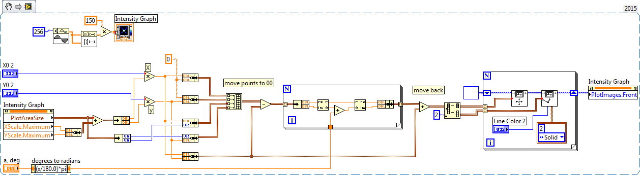
Draw the new lines on the graph of the intensity
I'm trying to attract the XY axes by an arbitrary point on a graph of intensity. I can draw two lines across the image (suite of messages like this link below), but they don't really seem FDNE to the top one the coordinates I spesify. I know that I have to correct the fact that the vertical scale increases from top to bottom, but how do I draw lines to the (x 0, y0) position I spesify? It seems that the lines are superimposed on the image, but not related to the axes of the actual intensity chart.
http://forums.NI.com/T5/LabVIEW/overlaying-XY-line-onto-intensity-graph/TD-p/398963
but you need made "vertical mirror".
-
programming Tektronix mixed signal oscilloscope
Hello
I'm using Labview programming to control tektronix oscilloscope to mixed signal 2014
Initially, I tried to control the vertical position and vertical scale of waveform.
It works but it takes a few seconds(5-8sec) disables it.
I tried to understand. However, I am unable to do, could you please help me what I need to do to reduce the delay time
Here is the block diagram of my vi
Hello
Email ID: [email protected]
Try to put two entries in the same loop, to run in the order of wiring.
In addition, you must add a waiting inside the loop (maybe 100 ms) to reduce the rate of update of the VISA application.
A stop button would be nice, too.
The way you wired things upwards, the two loops are trying to write their orders as quickly as possible on the instrument at the same time.
This most likely disrupts the scope.
You're also hogging your processor by not having is not a wait in there.
In addition, you close the VISA reference in two places, not that you would never get there because your curls are endless...
Klaus
-
How to add an axis mutual to a xy chart?
Dear freaks,
I'm sure that some of you are dealing with ghosts from time to time. Particularly in the field of infrared / contribute spectroscopy, it is common to work as well with the wavelength (nm) and the wave numbers (cm ^ - 1). While displaying the spectra in a xy chart, I would like to have two categories, a display of the wavelength, the other the wave number. Wave number / cm ^-1 = 10 ^ 7 x wavelength / nm.
No idea how to create this second axis? I guess this could be done using an image control. A better idea? How about the design of an X-control?
See the attached screenshot. The second axis was simply generated by allocating inverses of the extrema of the first axis of extrema of the second axis. Between the extrema the second axis is still divided linearly. This is not correct, of course, because of the reciprocal relationship between the wavelength and the wave number. Rather, each tick on the first axis must be converted to a tick on the second axis using the formula for the given above interconversion.
I'm afraid that my description of the problem seems rather odd. However, I am convinced that the problem is of general interest altogether.
Curiously waiting,
Peter
This one is a bit more friendly that it uses a table for reciprocal scale, which makes it easier to define how many values you want on the axis of the wave.
In addition, it sets the horizontal and vertical scale position, so you can move the chart anywhere on the screen and markers will follow.


Maybe you are looking for
-
is it better to save the photographs digitized as TIFF or JPEG
I just bought a HP envy 5532 I am scanning in old photos and I would like to have the best resolution the options are TIFF or JPEG - who should I chose? Thank you very much
-
1000 HP NOTEBOOK PC: Hi Please help me too.i need to know the bios password for my hp.
Please kindly help me. so I can use my hp in a good way. I need to know the password of bios of my RESUME... pls can anyone help me how can I remove it so I'm not paying expencve to solve this. my hp 1000 notebook pc running Linux ubuntu 13.10
-
Scan from String - Remove comma
Hello LabVIEW community. Here's an easy one that made me a bit puzzled. Then of course, it's not easy for me. I am using string analysis for city, State, Zip from a string. I can build the string that I have just described by commas using the For
-
Updates does not not (KB.982524) (KB2418241) (KB2414673} can anyone help
Pack 3 for Windows Server 2003 and Windows XPx86Service cannot install these updates
-
Downgrade HP 15-r011dx for windows 7, need help finding drivers
I installed Windows 7 64 bit on my new laptop HP 15-r011dx and can not find the drivers for the wireless network adapter. Any help would be greatly appreciated! Thank you in advance!