scale vertically osilloscope
Hi, I oscilloscope agilent DSO7012B, I started DEVELLOPING this device in labview interface, but I have a big problem on the vertical scale, I can't settle between vertical scale and mitigation of the probe to have a vertical scale of 10mV to 5V/div @ x 1 probe 100mV to 50 v/div @ x 1 probe 10 v to 500 v/div @ x 100 probe 10V to 5000V/div @ x 1000 probe 100V to 50000V/div @ x 10000 probe 200mV 100V/div @ 20:1
If I understand correctly, you'll have to do some arithmetic make use of graphical property nodes. As I said, the scope does not accept orders volts / div. You simply specify a maximum voltage personally, I think it's a better option for the user. In any case, if you set the size of the chart, you can use the button for to scale the chart. Say you have 10 divisions and 1 volt per division. The actual parameter that you pass to the function of scope of configuration is then 1 5 times (the number of positive divisions. You can also cheat a bit and set the scope to its physical button volts/div and do a reading of its value range. The button can be connected to an instruction box with the values of the scale. Just don't use a knob for dbl. Use it as a whole with text labels.
Tags: NI Hardware
Similar Questions
-
HP 7510 Duplex problem, scaling of axis of ordinates?
I read about the problem with additional/updated margins across the vertical duplex enabled on HP OfficeJet 6500.
I also found this question in a review of HP Photosmart 7510 [ http://www.trustedreviews.com/hp-photosmart-7510_Printer_review_performance-and-verdict_Page-2#tr-re... ].
> When printing duplex, the machine seems to use different inks for front
> and back faces of the pages and to automatically reduce the size of the images on the page.
> but not by as much as make heroes of Kodak. We can understand this duplex
> motor may need large margins, but still feel the driver software should let you know.
(1) is it by chance the same problem with "crushed" pages (to scale vertically) as in HP 6500?
(2) what are the minimum margin of top & bottom when printing in duplex mode on HP Photosmart 7510?
===============================================================
More information:
Several other users have confirmed the problem in discussions: http://h30434.www3.hp.com/t5/Printing-Issues-Troubleshooting/Officejet-6500A-PLUS-Duplex-scaling-iss..., http://h30434.www3.hp.com/t5/Printing-Issues-Troubleshooting/6500A-Plus-AiO-Duplex-Issue-Margins-Off..., http://h30434.www3.hp.com/t5/Other-Printing-Questions/HP-6500A-Adds-extra-1-2-quot-margin-to-top-amp...
There are also two possible solutions:
(1) remove the extra HP software [from: http://h30434.www3.hp.com/t5/Other-Printing-Questions/HP-6500A-Adds-extra-1-2-quot-margin-to-top-amp... ]
---------------------------------------------------------------------------------------
It was utilities HP Print clean which was causing the problem!
I remembered occuring problem started when I installed the hp (HP monitor) utilities, in order to use network scanning. Before that, I only installed the drivers.
Delete all HP bloatware and you should be able to print correctly.
---------------------------------------------------------------------------------------
(2) use the other driver [from: http://h30434.www3.hp.com/t5/Printer-All-in-One-Install-Setup/Officejet-6500A-PLUS-Duplex-Fix/td-p/6... ]
---------------------------------------------------------------------------------------
Hello world
I thought I would post this for others who have experienced the same problem I have with the default drivers for a 6500 Officjet MORE where what print in duplex mode, the topic on the axis there appear shriveled.
The fix was given by a person to the HP Technical Support...
First turn off you will want the printer already available on the computer before you continue.
- Go to Start -online device and printers -online, then click on the "Add a printer" button in the upper left corner of the device window.
- Click on the button "Add a local printer" (choose this option if you do not your configuration)
- Check the box "use an existing port.
- On the drop-down list, select the option "CN115130TP05JW(not the fax one) .
- Now in the list manufacturing to the left, select "HP".
- The printer the right list, select "HP Deskjet 6980 series (HP)" "
- "Once the pilot moved to enter in the" 'devices and printers ' window and right-click the newly added "HP Deskjet 6980 series ' and select" "printer properties ' on the drop-down list."
- In the HP Deskjet 6980 Properties window, click the 'device settings' tab at the top of the window.
- In the list of parameters, search for "Unit duplex (for printing on 2 sides) ' and select it.
- Once highlighted, select in the drop-down list ""Installed "; "
- When finished press apply
- Now go to what you use to print documents and then select the "HP Deskjet 6980" as your printer. Activate duplex printing and you should see the pages to print correctly.
Hope this helps someone who had the same problem as me.
---------------------------------------------------------------------------------------
In my time working with printers to this problem, I came across a viable solution. The key is to use a different printer driver to print, but to make sure that you use the right one. The document that I have a link in my previous post was ment to point people towards a simple solution, but that doesn't seem to work. I tried another way of attribution of other print drivers and other drivers that may work better. I found that the 990c Deskjet and Deskjet 450 driver work as a generic driver for most printers and retain most of the key features. These drivers allow the copy double-sided without distortion. I'll link to a post I did with the new instuctions below. I'm sorry that I don't come back to update this post as soon as possible.
How to assign other print in different Versions of Windows drivers.
-
Hello
Someone has a tip in which can do for that this content to scale vertically, when I change the size of the browser?
http://www.dandalo.NET/Teste/lazy-Patricia/3/48.html
Joy
Dandalo Gabrielli
For re-scalable foreground images, remove widths from pixels of images with parent containers.
Add this to your CSS:
IMG {}
Max-width: 100%;
vertical alignment: starting point;
Display: block;
}
Nancy O.
-
• Characters Panel is reset to 0 by default when you hit 'paintings' in the old table (CS5)
Hello-
Colleagues of my friends complain about Illustrator CC (17.1) and old tables of CS5.
We recently made the upgrade to CC (from CS5).
And we noticed a strange behavior, when you open a file in the tables.
When we try to change the tables within an existing table (table), well the 'characters' Panel is reset by default (leading, H/V scales, vertical offset, kerning,... are lost).
Is this a bug?
Or y at - it a logical reason?
How could avoid us this (ie. the table is formatted as it is), because we have thousand of these 'old' tables in our. Documents to HAVE it.
Thanks for any input.
Good day...
-Dimitri
Work in CS5 on old stuff and use CC for something new. There has been a change in the text in the CC engine and any attempt to change the text inherited in CC will cause the reflow.
-
I was wondering if someone could help.
I would like to make some type 3D with altering the original letters, still attached. I'm guessing that this will involve the 3D, extrude and bevel effect, but I can't work exactly what settings should I use. It's almost a sort of shadow vector I'm after...
Any help would be appreciated.

Use the 3-d with the following parameters:
45 °
-35 °
30 °
Perspective: 0
After that, apply the effect of transformation with these settings:
scale: vertical: 173,5%
turn:-45 °
Then you can change the 3-d effect again and adjust the depth, lighting etc.
-
There seems to be something wrong with the tools of scale and turn freely when they are used to transform radial gradients.
I did a radial gradient circular, gray in the middle and white on the Board.
When I try to stretch horizontally, false that the container but the slope remains circular, produce nasty hard edges at the top and bottom.
But if I try to stretch vertically I get normal results. So I have to scale vertically and then rotate 90 ° to get what I want.
Nothing about this in the help, the files and the results are the same if I use the scale or the free transform tool.
Does anyone else have this problem?
CS3 incidentally.
The problem exists also in CS4. Here is a screenshot of what Steve reports.

-
Spacing of objects proportionally
I know the basics for copy and Extensible objects (using the transformation of each) but I'm wondering how to change the spacing between the objects.
For example, say I have a row of dots, with the transformation that each I can enlarge then a percentage whenever they are copied. So if I do the largest 20% every time, how can I change the spacing between them to more than 20%? So I can go in a row small points far apart (less than an inch in height) to a row of points all consolidated (less than an inch in height) with each step being proportional to 10% or 25% or another?
Hope this is clear enough.
Thank you
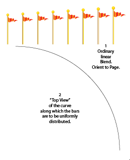
Think orthographically.
The type of distribution you are trying to reach can be considered the "side view" of objects all too distribtuted around a quadrant of a circle. The 'view from above' would be a quarter circle.
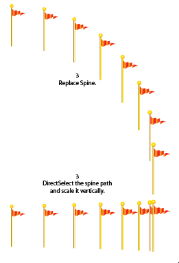
Make a regular linear mixture, draw a circular arc of 90 degrees and replace spine of the mixture by the CRA. Use snap to the Page for the mixture. Spread the mixture, dissociate and align objects vertically. (Or to keep the live mix so that you can always change the number of intermediate steps, directSelect his path of the spine and to scale vertically.)
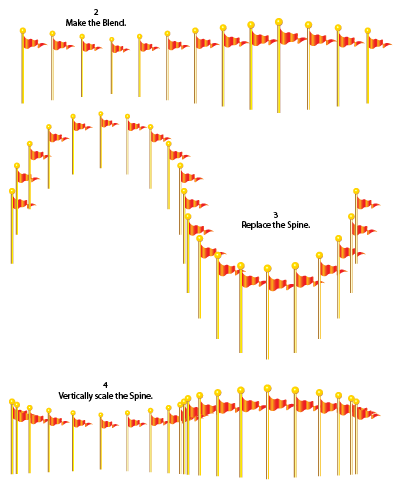
The method is applicable to a curve "top view" of any form. For example, imagine a sidewalk in the shape of OSH, bordered by the evenly spaced flagpoles. Draw the top view of the road to passage. Keep in mind the distance/farness of the steps, compared to the "side view" line of sight and milestones to scale accordingly:
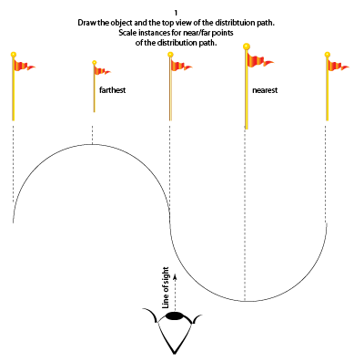
(Strictly speaking, the spacing is correct for an orthogonal view, in which the flagpoles are not resized to simulate the distance/farness. But it's not quite right for a perspective conical design because the spacing between the flagpoles at the furthest point must be less than the spacing at the closest point. but that can be bypassed by a little more than construction. It depends on if you, in fact, try to make a point of view converge drawing and how mechanically correct, you feel it must be).
JET
-
vertical scale 5152, set up the time
I use a pxi-5152 in a pxi-1033 chassis.
I want to play a trick and change the vertical scale between my measurements to increase the dynamic range of a signal that I'm scanning. I made a loop and changed the vertical scale property node after each measurement. It works, but when I timed it the loop, she seems to take 80 ms. I need to do in less than 10 milliseconds.
Is it still possible? I see the real time it takes for the scale change or there at - it something to speed up?
I also have access to a PXI real-time with the same card. Could only accelerate things or is the digitized the limiting on the change of scale factor?
Thanks for any help
-Rich
Hi rich,
I see the real time it takes for the scale change or there at - it something to speed up?
You probably see the effect of the two. There may be something of software that you can do to improve it, but there's always a material limitation when you do this kind of operation. Switching of the means of vertical lines change from one type of mitigation to another path. This means there is sedimentation time involved (electronic and mechanical, with obviously dominant mechanics). The main element in the run-in will probably be the relays that are reversed. There must be a minimum period after the passage of a relay to ensure the data read by the digitizer are correct / valid.
Since you know your signal is going in a direction (descending), then you may be able to improve somewhat by calling the property to write the new range, and then commit node & initiating in a loop which contains a minimum transformation (possibly using queues in LabVIEW to transfer the data in another loop of treatment). If you need treatment in the loop, you must perform the treatment after niScope commit but before launch niScope. This will allow the digitizer begin to settle in the new configuration, and you have to wait less time when you're ready to call to initiate.
I also have access to a PXI real-time with the same card. Could only accelerate things or is the digitized the limiting on the change of scale factor?
Real-time processing ensures determinism, it does not necessarily speed up the application. Determinism and defining a specific priority for calculations of software can help speed upward the software that you are running, the interface of low-level PCI/PXI bus driver with the instrument probably will not change radically. You can certainly try though and let us know what you measure.
I can understand if it is a fundamental issue, because normally people are not change the range of vertical entry on the fly, but if there is a way around it, it will avoid the need for me to put an amplifier with variable gain on the front-end server or buy a digitizer with more bits.
This isn't a perfect suggestion, but just a thought: If you have several scanners at your disposal, you might try setting each to a fixed vertical range and split the signal among them. TClk, you can synchronize these devices together to make sure your data points are sampled at the same time, and then introduce delays in the initial on each digitizer trigger so that they take account of the waveform in a cascade mode. For example,.
Digitizer #1, attached to the greater vertical reach, would have no time limit from the time wherever the trigger is received.
#2 digitizer, set at a smaller vertical range has a fixed period of (10ms?)
Digitizer #3, value the smaller Beach, has a fixed time (20ms?).
Otherwise, if you have assistance with the OR, you could try to call a technical sales engineer to discuss other possible options.
-Andrew
-
Hi, how to create a vertical scale for an altimeter or a speedometer whith LabView?
Fred of tanks
-
Wavy vertical lines distort up and down when I use the scale to the size of the frame in CS6
In recent days, while I import images HD to SD comp and use the scale to the size of the image now I have these wavy vertical lines at the bottom and the top (instead of black). I have a problem when images are suspended, when I play it's ok, and also the problem appears when I export images. I have to reduce my images manually in some 62% and then it's just the way it should be.
See the image below (to LEFT - when I read my clip, RIGHT - when it is paused)

This bug should be fixed in the next version of NVIDIA. Try to restore the previous version of the driver.
Peter Garaway
Adobe
Premiere Pro
-
I have a partitura with 18 instruments. Problem is that only 16 of the sheed. How can I vertically down the music?
Make a score set with 18 all instruments. Then use the scale parameter set score to all fit on a single page.
-
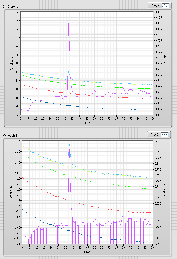
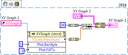
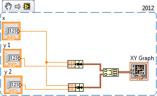
Trying to insert 1 vertical line on xy-graph, but get more. Can someone give me a clue on what I did wrong?
Adding to my post: a point in this case is a pair of a x and a value of y

If you enter - Inf and + Inf for y values that you should always see a line (well, ignoring logarithmic scale
 )
) -
That really means the vertical range? And the gain factor?
The NI PXI-5102 digitizer: that means vertical range really means, it is the range of voltage of the signal to be measured or the signal to the ADC input terminal?
How to control the gain of the digitizer? And what are the factors that can affect the gain?
The portrait is located between the valid entries range of the digitizer on that channel. If you set the interval to a value that is not valid, it will be converted to the next highest value. This is the way you control the gain of the digitizer. It is easier to define the vertical range on the maximum expected range of your input signal and allow the driver to NO-SCOPE compel the beach to the next highest value. This allows you to use your code effectively with more than one type of digitizer (5102 and 5112). For example, you know that your input signal has a range of 3 v (+/-1.5V). Set the vertical range at 3. OR-SCOPE that will force to 10V, the next beach valid more high for the 5102. You can find the valid vertical beaches for your device in the folder of Documentation OR-SCOPE in your Start menu or online.
Mitigation on your scope probe will affect the vertical range of the device. If you have a 10 X probe and defined the vertical range to 10, the actual vertical scale will be 1. You can have NO-SCOPE figure that out for you by setting the mitigation of the probe with vertical Configuration.
More information on the routes of entry, and gains are available in NO-SCOPE help about using vertical configuration.
-
Get chart scales and grids to display only whole numbers
How to make a graph of mixed signals as indicated in the attachment to only show whole on the y axis and reduce the grid to do the same thing?
Hello
programmatically, you have a property node for the scale that should do the job: 'increase '.
=> property node, Y scale, range, increment.
The grid will follow.
The minimum increment depends on the vertical size of the chart (and the size of police marker I suppose, who also has his property node)
example attached, hope it helps.
Antoine
-
How to set the vertical position of the oscilloscope (Simulation)
Hey guys...
I think do a very basic oscilloscope in labview (simulation only).
So I'll show 2-4 channels to the oscilloscope. For this I will use a waveform graph and show the parcels of 2-4 in the same graph.
But how to define the vertical position of the individual parcels (channels) for comparison?
Suggest an idea please...
Make additional changes the values in your table do you do whatever will be will be incorrect. For the offset adjustment, assign each parcel at a different scale y and set the minimum and maximum of the scale up and down the waveform.


Maybe you are looking for
-
Toshiba NB200-10Z change HARD drive to SSD
Hello. I plan to buy Toshiba NB200-10Z netbook. I would like to ask if the next drive 'OCZ-OCZSSD2-1VTX60G 60 GB Vertex Series SATA II 2.5 SSD Drive' will fit this netbook? Post edited by: Lee
-
Safari, chrome time cannot access most of the sites on my MacBook Air
All of a sudden since the morning of today I can access most of the sites except Google, Facebook, and LinkedIn. Safari and chrome have the same problem. I tried to empty cache, remove extensions, change dns 8.8.8.8 in Network preferences, but nothin
-
Download the SequenceFile associated with UIMsg_StartFileExecution
I'm catching the UIMessage UIMsg_StartFileExecution and want to update my UI to indicate which SequenceFile is executed. I can't understand how to determine which SequenceFile is associated with this message. The two UIMessage.Thread and. Run are n
-
No sound on the TV when connected over HDMI
I have HP G62 laptop. I seem to have lost the audio HDMI when I connect to the TV. Help, please! Have checked the Audio on the control panel and seem to only Realtex Hi Def speakers have implemented.
-
Replace the HHD Pavilion m7 with SSD boot drive
I have a Samsung 840 Evo SSD that I managed to install in the 2nd internal drive Bay. It works great as a second internal drive, but I want to make the boot drive for Windows 8.1 or simply swap with the internal HD, which is the current startup disk.