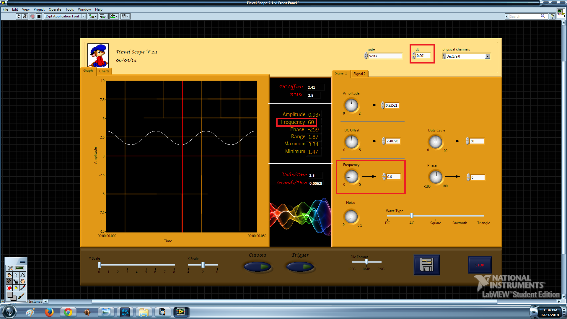
Virtual oscilloscope; Setting frequency of data acquisition
Hello world! I tried to program an oscilloscope using the Labview software and acquisition of data USB-6009. It will be very soon, but I can't seem to set the rate of acquisition of data at the correct speed. Let me show you what I mean:
waveform dt: 0.1
Frequency: precise
Limit: 5 Hz
Explanation: "[0.1 dt] is 10 Hz. Therefore Nyquist function, 5 Hz is the highest frequency that you can enjoy. Anything more than that will alias down in the 0-5 Hz range. "- Crossrulz

waveform dt: 0.001
Frequency: x 100
Limit: 500 Hz
Explanation:? The frequency seems to be dividing by dt at some point.
I like for this oscilloscope simultaneously read faster than 5 Hz and be precise. Here's my block diagram if someone would be willing to take a look:
Create the channel-> read-> buffer / collector-> Trigger-> Append--> measures/graphic
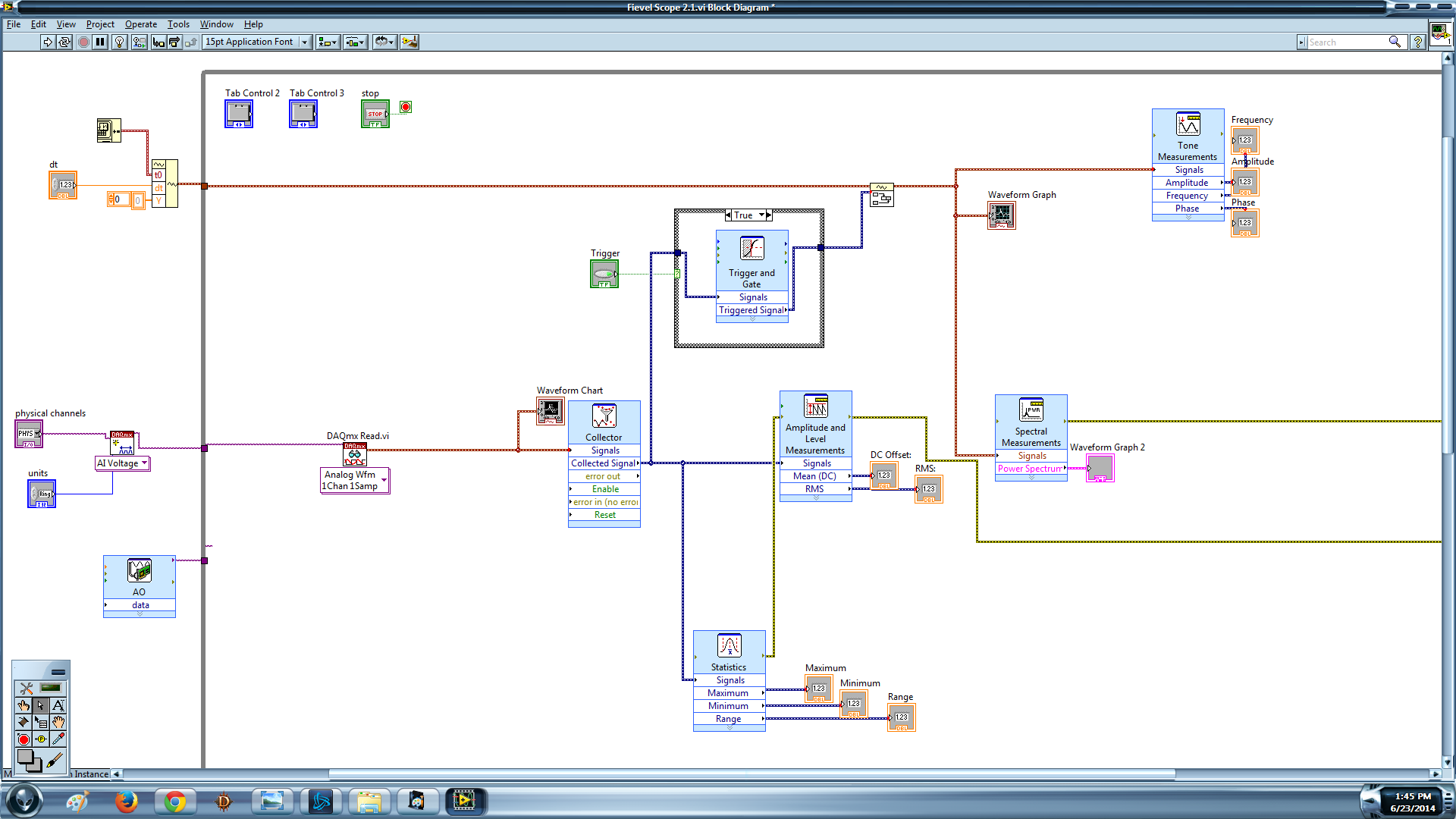
A last word: the dt that I am changing is on an empty wave form which I enclose with my signal to input in the upper left corner.
You run the examples that come with LabVIEW? STOP using the 1 sample DAQmx Read. Right-click on it, and change the type. The other mistake would come if you have changed the similar to the task. Delete this part because you don't use it.
Tags: NI Software
Similar Questions
-
Real-time display at the high frequency of data acquisition with continuous recording
Hi all
I encountered a problem and you need help.
I collect tensions and corresponding currents via a card PCI-6221. While acquiriing data, I would like to see the values on a XY graph, so that I can also check current vs only voltage/current / time. In addition, data should be recorded on the acquisition.
First, I create hannels to analog input with the Virutal DAQmx channel create, then I set the sampling frequency and the mode and begin the tasks. The DAQmx.Read is placed in a while loop. Because of the high noise to signal, I want to average for example every 200 points of the current and acquired for this draw versus the average acquisition time or average voltage. The recording of the data should also appear in the while loop.
The first thing, I thought, was to run in continuous Mode data acquisition and utilization for example 10 k s/s sampling frequency. The DAQmx.Read is set to 1 D Wfm N Chan N Samp (there are 4 channels in total) and the number of samples per channel for example is 1000 to avoid the errors/subscribe for more of the buffer. Each of these packages of 1000 samples should be separatet (I use Index Array at the moment). After gaining separate waveforms out of table 1 d of waveforms, I extracted the value of Y to get items of waveform. The error that results must then be treated to get average values.
But how to get these averages without delaying my code?
My idea/concern is this: I've read 1000 samples after about 0.1 s. These then are divded into single waveforms, time information are subtracted, a sort of loop to sprawl is used (I don't know how this exactly), the data are transferred to a XY Chart and saved to a .dat file. After all that's happened (I hope I understood correctly the flow of data within a while loop), the code in the while loop again then 1000 samples read and are processed.
But if the treatment was too long the DAQmx.Read runs too late and cycle to cycle, reading buffer behind the generation of data on the card PCI-6221.
This concern is reasonable? And how can I get around this? Does anyone know a way to average and save the data?
I mean, the first thing that I would consider increasing the number of samples per channel, but this also increases the duration of the data processing.
The other question is on the calendar. If I understand correctly, the timestamp is generated once when the task starts (with the DAQmxStartTask) and the time difference betweeen the datapoints is then computed by 1 divded by the sampling frequency. However, if the treatment takes considerable time, how can I make sure, that this error does not accumulate?
I'm sorry for the long plain text!
You can find my attached example-vi(only to show roughly what I was thinking, I know there are two averaging-functions and the rate are not correctly set now).
Best wishes and thank you in advance,
MR. KSE
PS: I should add: imagine the acquisition of data running on a really old and slow PC, for example a Pentium III.
PPS: I do not know why, but I can't reach my vi...
-
data acquisition won't taste at the specified rate
Material: C - DAQ 9178, AI 9239, inside a servo and an encoder potentiometer module
Setup: I use the 9239 to measure the angular position of my servo and encoder of trees by streaming came pressure pot of the servo and my encoder. I put the sampling frequency on the DAQmx - Schedule VI to 100 Hz.
Problem: I don't think that my DAQ is sampling data at 100 Hz because my VI registers more than 10 000 data points for a 10 second test. In addition, every time I have save my data in a text file, the vector of time my test data resets after a number of iterations.
To debug, I tried the following configuration:
I've defined the sampling frequency of 100 Hz (or is that s/s?), the samples per channel (size of buffer for continuous mode) at 2000 samples, number of samples per channel up to 10 and loop milliseconds timer on my VI at 10 m accordingly, data acquisition would send 100 samples per second (or 1 sample every 10 ms) on my PC buffer (which could store 20 X that amount). Then LabVIEW would read up to 10 samples per loop iteration (which is itself ~ 100 Hz) and work with these 10 samples inside the loop. However, since the loop is operating close to the sampling frequency of data acquisition, then LV should only work with 1 sample each iteration of the loop (100 Hz / 100 Hz)-not the 10-sample-max that I specified.
However, I stumbled on "error-200279: the application is not able to cope with the acquisition of material" when I ran the program. Why?
My code and materials should be easily able to cope with data acquisition - at least the way I put it in place
This whole situation wondered my fundamental understanding of data acquisition timing, so I would really appreciate an explanation of exactly how to deliver DAQmx uses data synchronization, why my DAQ sample at 100 Hz, and how can I fix the calendar specified by the user.
Thank you!
aeroAggie wrote:
The C - DAQ 9178 there some minimum sampling rate I will not meet?
It's actually the 9239 that limit your sampling rate. Read the data sheeton page 5 there's available data rates. In short, your data rate allowed is 50kS/s / n, where is goes from 1 to 31. 50 k/31 gives you 1.6kS / s. So, it's the minimum sampling frequency that can be used.
-
Input module of data acquisition can be read by two or more LabVIEW vi at the same time % 3F
I use the DAQ palette in LabVIEW to read the virtual channels of the input data acquisition module. I've done several VI who read many entries of three modules of simulations. The problem appears when I run two or more VI´s reading entries from the same virtual module (for example. first.VI module 1 input ai0 and second.VI bed ai0 entry module 1 bed), when this happens the next errors are shown:
Error-50103
Platform AND Services: The specified resource is reserved. The operation could not be performed as indicated.
and
Error-200022
Resource requested by this task has already been reserved by another task.
It's worrying because I want to get the DAQ chassis and some modules, but if this problem is present with physical equipment my application may be unnecessary. This means that entry module only can be read once at the time?
I m using global variables in each Subvi to share data with main VI, however, I found the solution in a different way... I just changed to single channel and dbl sample playback mode, so I Don t need to clean up the task of reading in my subVI´s, the zeros isn´t problem here, and the six subVI´s work at the same time!
Thanks for the tips!
-
Virtual oscilloscope; Slow Data Acquisition (limit of 5 Hz)
Hello.. I tried for a some time now schedule a virtual oscilloscope using the software or Labview and materials acquisition of data USB-6009.
This has been my best attempt to date: http://www.andthenbam.com/FievelScope.vi
I seem to only be able to measure frequencies up to 5 Hz, then the frequencies of signals begin to repeat themselves. I am aware that this device is capable of a MUCH faster speed. I'd appreciate it if someone could take a look at my VI and recommend a solution.
Acquisition mode: 1 sample (on request)
Buffer: 100 samples
I failed to raise other modes of acquisition work. Help, please!
Here I explain my problem:
http://www.YouTube.com/watch?v=k8oI9mL8ZD4
Ty
Your problem is that you are setup to do one sample on request. This means that you count on the loop to set your frequency of acquisition. You probably really want to continuous samples with a rate that is much higher, depending on what you are trying to capture.
Looks like you're trying to sample every 100ms. It is 10 Hz. Therefore Nyquist function, 5 Hz is the highest frequency that you can enjoy. Anything more than that will alias down in the 0-5 Hz range.
-
Sampling frequency and Nyquist theorem - data acquisition
Hi all
I have a rectangular steel beam that is affected with a weight of 100 kg and I would look for the modules able to sample the signal correctly.
The Nyquist theorem says that if half of the sampling frequency is higher than the input signal, it will be recorded correctly.
What I think about it before you buy a data acquisition module to find the signal of the rectangular steel beam? I will perform an analysis model by finite elements using the elastic properties or properties of plastic? Is the natural frequency of the associated structure of the input signal?
Thank you
Husband
Some technical assistance is appropriate, determine that the higher frequency component is interesting to your signal. Set your frequency of sampling to twice this value. In addition, to protect data, to build a filter of antisliasing of material it alleviates any energy above the highest frequency of interest.
Mike...
-
Generate data with 6722 and reading back with 6221 - it visualization with a virtual oscilloscope
Hello
I generate an analog signal with the 6722 and want to read with the 6221. The results shall be included in the virtual oscilloscope. My problem is that I don't know where to put the signal-chart and that I really need to use type. The second problem is that I have no idea how do I choose a time scale and where and how to define. Finally, I have that image that I get on the real oscilloscope with data generated by 6722 on the virtual oscilloscope with the 6221. Initially, the oscilloscope should have no (mode of operation only) trigger as the 6221 has only a digital triggering.
For the moment, I have a loop that generates the signal using a sequence. Now, the question is where to put the signal-chart and what settings should I use for reading back information (1 sample, continuous, etc.).
Thank you
Verena
Hi db2nc,
Here is a link for an example of our community. It shows you an example with which you can generate a signal on output and gain on a different entry.
I think that's what you want to archieve.
Loopback synchronized analog output of analog input
concerning
Michael
-
LeCroy Waverunner 640Zi - Data Acquisition
Hello... I'm trying to set up my oscilloscope waverunner with LabVIEW SignalExpress for data acquisition.
I took the steps so far:
1 pulse generator hooked to scope of signal generation
2 USB scope to the installed computer with LabView
3 downloaded lecroyscope driver 3.2.9 - x 64
I turn on the scope and plug in the USB to the computer and SignalExpress begins.
a. start by using data acquisition
b. Add step/aquire signal / IVI aquire / IVI brought aquire
c. create new IVI session... resources descriptor (I choose my USB device ' USB0::0x05FF:0 x 1023: 2812N61507:INSTR '), I select the right driver (lcscope), and I do not click enable simulation data, press ok
d. I still receive configuration errorse. did the research... some forum said goto MAX, find drivers and uncheck the Cache and the exchange of check
f. attempt to initialize... always get config errors.
g. return to MAX... change to simulate with specific driver.
h. initialization works... NO errors, BUT no data are acquired.
Help, please!
Hello
Sorry to jump in if I was out of the country for a while and am still catching things in my office.
I think you are looking for someone to say yes, "you can connect to the scope with NOR-MAX and VISA, and here's how interactive tool do"
A few things:
LabVIEW for XStream extended driver is the right one. It works with all the TeledyneLeCroy Windows based scopes.
As I see has already been noted. (I'll give Kudos soon), the scope of application must be configured to use interface USBTMC. To do this, go to the drop down Utitlites on the scope menu and select "utilities configuration... '. "in the tabs that appear at the bottom of the screen, select the 'Remote' tab and make sure that the interface type is set to USBTMC. This will also show you the VISA resource (I see it in the title of the image of VISA interactive tool indicated in a previous post).
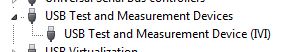
Once this field is selected, the PC should detect the USB connection and install the device. (you can see in your device manager as a Test of USB and the measurement device):
Once this is done, you can then enter the NOT-MAX and it will detect and display resources. You can now communicate with the device:
If you have problems, do not hesitate to give me a call and I'm happy to walk through it over the phone.
Kind regards
Leonard Brown
Technical sales engineer
Teledyne LeCroy
1-800-553-2769 -
LabVIEW data acquisition Setup Multifunction DAQ
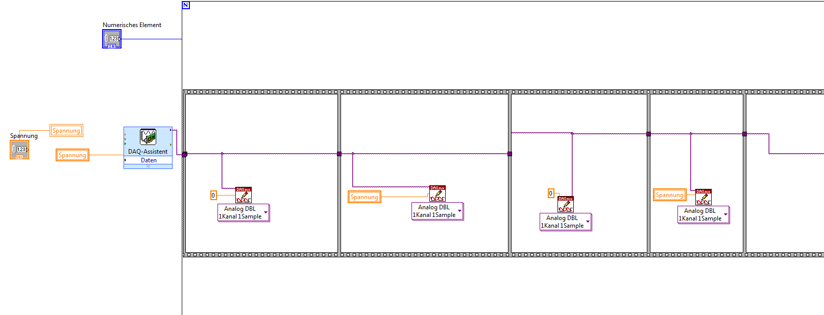
I have doubts as to the acquisition of data in the LabView environment. I used the block diagram (Figure 1) below to review the update of the readings for the execution of a loop.
Block 1 has been used to enable a task (first steps) with 3 channels (al) analog input AI3 and even set up the channel. In this case, the data bus (data-block 4) are construindos by 4 columns of data (provided by task 3 AI3 more).
Block 2 is used to set the sampling rate in this case is 1 Hz (1 sample per channel x 1 rate).
In this case, it worked as I expected (Figure 2). This allows to conclude that the interval between each sample was 1 second. The saw took a second in the iteration.
The second step was to change the amount of data sampled in accordance with Figure 3 channels in block 3.
Now, each channel showed 10 samples, while there are 4 channels configured, we have 40 samples. In this case the iteration totalled 10seconds (point to 1 Hz and 10 samples per channel-figure 4).
The first question is what is the time between each sample obtained by channel?
In this type of configuration (multiple channels), block 3 provides 10 samples in each channel, as well as the sampling is done, IE, the block gets 3 10 samples from a channel and passes to the next channel or gets 1 comp each channel and repeat this process up to 10 samples per channel?
What is the best way to make sure that the interval between each sample is constant?
If anyone knows any text that explains what the function blocks of data acquisition information please.
Thank you
Gabriel
Well, there are several ways to read the signals of multiple signals, and each of them has different behavior. I couldn't see how you get mutiple channels, because in the two codes, you set a channel in your codes. Take a look at this figure:

Here you can see how to set multiple channels using DAQmx, using commas to separate the channels. About the ways different ways that you can read the signals, you can look at the links I sent in my first post to learn more about them.
In a few words, the time between samples from the same channel is T = 1/Fs, corresponding to the sampling frequency Fs. It is not a rule to determine the interval between samples from different channels, because it will depend on how you did your code, and as I sad, there are different ways to do. You can acquire the samples at the same time, or you can configure your code to read a fixed number of points of a channel and then read another fixed number of samples to another channel (https://decibel.ni.com/content/docs/DOC-28279). You can acquire a finite number of points, or you can acquire all the time. Yet once, take a look at the material that I have already sent. It will help you find the best solution to achieve your code according to your application.
Kind regards
Pedro
-
DAQmx data acquisition with persistent error of nyquist
Hi, I created a multi channel data acquisition vi (accelerometer 2 and 1 sound pressure) using models for producer. The vi is attached. Thanks to labview 2011. I get the error of nyquist (2 enclosed) when you make a bandpass filter between 50 to 5000Hz. This happens despite having put my sampling rate to 22050Hz. When I checked the output of wave I noticed that the signal has a dt 1 s. The text output to check the result. I could not understand how this is so since I had set the sample rate to 22 k Hz. Any help will be much appreciated. Thank you.
I would do something like that. You must calculate the dt of the set (with the recipricol) sampling frequency and use to initialize the shift registers. This way you only need to change 1 constant if you need to change your sample rate.

-
Conversion rates for simultaneous data acquisition
I use a Mech multifunction data acquisition. / s/SMU-6366. The maximum sampling frequency for the analog inputs is 2 MHz. Is the time of actual conversion of CDA always 0.5µs, or t - it change with the evolution of the sampling frequency? Can I set the time of the conversion? Reading, looks with peripheral multiplex, you can set convert it clock and the sample separately clock. What is with simultaneous data acquisition?
Hi Daniel K..
It is a big question. I wonder if you get any errant behaviour - your card is not up samples as you hope?
Here is some information that might help you:
Wikipedia: successive approximations ADC
I'm not sure exactly what happens, but dare a guess time digitizing ADC does not vary with the frequency of sampling. And it will also be more than 0.5 US - it is more than likely faster than that.
I hope this helps. Good luck with your application!
-
Control and simulation and data acquisition
Hello
I am applying to motor control in Labview. I'm sampling speed from DC engine in real time through an acquisition of data. (my sampling time is 1000 samples per second)
Then wrap speed as input to a Simulation (simulation and design of the order) and inside the loop simulation, I have a PID controller. The PID has the actual speed of the engine for the acquisition of data and the engine reference speed as input.
Reference engine speed comes from the generator of signals (control design and simulation-Simulation) and is a waveform.
My step in the engine size is 1000.
I am running this application real-time and drawing the reference signal and the motor real signals. I run into several problems with regard to the calendar.
1. when I change the size of the step of the simulation loop, the frequency of squares of reference also seems to change. For example. What step size = 1000, duration of pulse = 1 s. What step size = 100, pulse width = 0.1. (My pulse frequency is 1 Hz, Simulation clock - 10 kHz). How step size can affect the pulse width.
2. can you explain the relationship between the DAQ, the Simulation step size loop sampling time, Loop Simulation period.
3. If I want to collect different sets of data using sampling different hours, it's OK to change the sampling DAQ time without changing the size of the step of the simulation.
Would also like to emphasize that the DAQmx calendar under sample clock mode is placed in front of the simulation loop and the output is connected to the loop simulation.
Appreciate any help.
Hello
Maybe some screenshots of your code would help. Furthermore, what you have read your samples together with your DAQ screws?
(1) If you have a waveform, the output is specified as:
For example, if you change the size of the step of the simulation loop, you change the simulation time which are introduced into the signal generator and affecting the waveform that you see if you do not have a size quite small step to characterize the waveform that you generate.
(2) sampling DAQ rate is the speed at which samples are taken on the acquisition of card data itself. The size of the simulation step, help. "Specifies the interval between the time when the ODE Solver evaluates the model and updates the results of the model, in a few seconds." Simulation loop, still using, "Indicates the amount of time that elapses between two subsequent iterations of the loop of control & Simulation.". " "Step size determine the value of t that is introduced to the functions you use in the loop simulation while the loop simulation period controls simply to how fast you change the following t value. The sampling rate of DAQ hardware is a clock of completely separate hardware controlling the analogue-digital on the DAQ card converter so that you can get a deterministic dt between the samples being acquired.
(3) you can change the schedule for the acquisition of data, but you will need to restart each time the changes take effect. If you change the calendar of data acquisition and want your values to correlate with your simulation, you will need to change your size of step as well.
-Zach
-Zach
-
Hi, it is impossible for the moment to install the driver for PCI Data Acquisition and Signal Processing.
I downloaded the driver from Intel, and it did not work... I found a version of this site for windows 8.1 unupdated and it does not work.
A little help?

Thank you!
Hello:
It could be one of two different drivers.
Try this one first, and then restart the PC.
This package contains the Intel Chipset Installation utility. This utility allows the operating system to show the correct name for the Intel hardware that is installed in the Microsoft Windows Device Manager. This package is provided for the laptop models running a supported operating system.
FTP://ftp.HP.com/pub/SoftPaq/sp75501-76000/sp75561.exe
If this does not work, try this one...
This package contains the driver which allows Intel platform dynamic and thermal firmware setting. Intel platform dynamic and thermal environment information system temperature and power use for the thermal protection of the system to work properly. This package is provided for the laptop models running a supported operating system.
-
Hi team,
I just install windows 7 edition integral and peripheral Bluetooth windows 8.1 is not be detectable, when I search for problem that I came across this PCI data acquisition and Signal Processing controller driver is missing and a unknown device driver missing shownup in my result of troubleshooting. Please help me
Please find the screenshot for your reference
Thank you
Hello:
See if these drivers work...
CQI PCI controller:
This package contains the driver which allows Intel platform dynamic and thermal firmware setting. Intel platform dynamic and thermal environment information system temperature and power use for the heat of the system
protection to work properly. This package is provided for the laptop models running a supported operating system.File name: sp71638.exe
Bluetooth:
This package contains the installation package driver for Realtek bluetooth in the laptop models running a supported operating system.
File name: sp71288.exe
Unknown dev:
This package provides the HP 3D DriveGuard software (HP ProtectSmart Hard Drive Protection) for the laptop models running a supported operating system. HP 3D DriveGuard software protects the drive hard by parking the heads if cell phone accidentally falls, or is suddenly struck by another object.
File name: sp71811.exe
-
Data acquisition reading incorrect when you use a loop
Hello
I wrote a simple VI (00, 01, 10, and 11) output to a circuit connected with 4 resistors. Based on what value the ciruit receives, it passes current through a particular resistance. It is again entered in Labview and traced.
The problem is when I send a particular value (i.e the 00, 01 and 10 and 11) and get that back, it's okay. But when I send and receive the consectively connected via the loop counter, they are incorrect (not synchronized with the number of the loop).
I made sure that circuit works very well. It has something to do with the loop synnchronization, reset, value compensation, etc. can be.
Please Guide...
Change your DAQ assistant that reads to be 1 sample on request.
Right now it is set for continuous samples. And 10 samples at 10 Hz. Then it runs and starts. The next iteration, you send a new digital out, but the wait for 4 seconds. When you read again, you get the next 10 samples that are put into the buffer of data acquisition, but now 40 samples have actually entered the DAQ buffer. In time your DAQ buffer will be finally complete and raise an error. In the meantime, you will continually read data continues to become more tainted by the iteration.


Maybe you are looking for
-
continue reading agilent 34970a error 113
I tried to use labview to make records of continuous temperature of a K type thermocouple and an agilent 34970 a daq and then graphically representing changes in temperature. I think this should be a fairly easy application, but I've been using the
-
When I try to go on IE I get the error messages - Windows cant find '00' make sure that you type the name correctly and try again. also get "could not load or run '00' specified in the registry. Delete it or make sure that the file exists. Help!
-
Photostory 3 on preview leaves the program
I have several computers (out of 30) in a laboratory where clicking on the preview makes the program stopped. We are Windows XP and all 30 computers must be configured the same. This occurs even after the recording of the photo Story and when there a
-
I use win 7. I want to change back to a configuration system beyond the restore points. HOW?
my system now LISTS the options to choose but in the words, no icons or images. It is a new thing. I don't like. It is anti-intuitive. How can I change the system.
-
One possible part of several groups?