Wiring directly AO on SC-2345
I'm trying to wire directly an analog output for my gas flow adjuster to set the tension and set the rate. I use a block of connection SC-2345 with an acquisition of data PCI-6229. The names of pin of the SC-2345, I should be connected to AO 0 (pin 1) and AO (2-pin) GND to J17. However, using my test panels I can't seem to control the OD 0 using my PCI-6229. Any thoughts?
As an update, the question was one to find the path AO to the PPI correspondent and corresponding with the AO on the Board.
Tags: NI Hardware
Similar Questions
-
I my house wired with ethernet and have logged as many devices via cat5e as possible. My problem is when I try to connect together the two apple airport extreme base stations and use the second to extend my network I lose the internet connection. I am able to extend without problems via radio, but since I plugged in the House tried to take advantage of the fastest method by cable.
Here's my network setup in a nut shell.
In the basement, I have my router from Verizon Fios (gateway 80211n) currently configured to provide all the space an Ip address via dhcp (disabled wireless)
Gigabit ethernet port 8 wired via gigabit switch through the cable between the bridge Fios and port 1 of the switch.
two iMacs wired directly the fios gateway ports 2 and 3
Base station extreme elementary apple (call it down at the moment) connected to the Fios bridge
Extreme basestation secondary apple related to extreme primary apple base station
Cable to switch TV
Nintendo Wii connected to the switch U
Apple TV connected to the switch
Drive Blu - ray connected to the switch
My mainly the Airport extreme is configured as follows
connect via DHCP
Address of the router is set to the Fios router
FOR DNS, I used back free servers like Google, and level 3
Wireless is set to create a wireless network
Security is set to WPA2 Personal
Turned on 5 GHz and 2.4 and 5 ghz are set to automatic
Router mode is set to bridge mode off
Second or first floor Airport extreme config
Connect using dhcp
Address of the router is also the Fios router
Servers DNS is empty
Wireless settings
Network is set to extend a wireless network
the wireless network name reflects my network
wpa2 personal wireless security game
Network
Router mode is grayed out and pondered or bridge mode
Second or first floor Airport extreme config...
.. . Network is set to extend a wireless network
Given that all routers are interconnected by Ethernet, you don't want to configure AirPort Extreme to "Extend a wireless network." This option should be used only if the connection between the wireless base stations. Instead, the two base stations must be configured to "create a wireless network. This is because that, with them all connected by Ethernet, you have the basis for a network of mobile type.
With this type of network, each router will broadcast their own Wi - Fi network, but because they will all use the same network name (SSID) and use the same type of wireless security and the password, all the wireless clients will see them as network «one»
-
I need 64-bit drivers for Windows 7 for HP ENVY 17-jo27cl
I searched the forum for a solution to this problem and didn't see anything for my particular model.
I gave to Windows 8 a relatively long test - about 2 weeks. Hatred is not strong enough a Word. I "upgraded" to Windows 7 Ultimate 64-bit. I have problems to find drivers.
I have no drivers for the cable or the wireless network connection, so I'll have to ask that question of my aging Dell.
I'd appreciate any help I can get.
You are the very welcome.
Try the Intel directly to Intel graphics driver
Audio... try this one:
The PCI device is the one.
The USB\VID_138A is this one.
Try this one for the 6007:
Try the wired directly from realtek network driver. a 5th on the list.
-
Access to the Marina wifi problems
I live in a marina and use the wifi from the marina. My iMac (2008, equipped with internal wifi) is low in the boat (galley down), which is fiberglass, but has wires and other equipment in the world. When it is docked (that's all I'm concerned about here), not a large part of the equipment works except appliances regular and battery 12v and 32v "offers/Chargers" I borrowed a Belkin range extender (1106v1 F9K), which helps, but not enough. It is an inner ring road and the line of sight to the antenna of marina (150 feet) and (less so) to my computer are not good. I have examined) 1 antenna USB iMac (--> Belkin?), 2) hacking a router not used the Belkin (cable?), 3) installation of a wifi antenna ($$) on my arch of radar which would have good line-of-sight and might, without effort, wired ($) directly to the computer or to an access point (terminology?) (?$). Next gen electronics marine start using some wifi and if this last combo would allow this traffic, it is worth the investment. There are other options for example. existing antenna (VHF?), beach (?) radome, beach dome (?) satellite. Here, the "old salts" around know the antenna, but not computers. I do not know! (But difficult). There are many other wifi signals locked appear on my computer. I am a small time internet user but considers Netflicks marina limit myself to only basic cable!
You aren't going to get the bandwidth for netflix on any shared... wireless system, so it's out of the question... you will need to hold for release into the atmosphere of TV or your collection of DVD/bluray.
Directional antennas are the key to this... WiFi is more powerful because the problem is receiving does not transmit.
And you need to get a direct line of sight to the wifi everywhere where it is setup in the Marina... because it is not possible to get the signal through some big boats steel nice... your fiberglass is very well... unless he has mixed in freezing metal. In any case on a boat to mount the antenna as high as you can... and the router with it... so you can connect to it by ethernet would be the best... Although you can use wifi if you wish, messy but possible.
You can buy outdoor combined AP suited perfectly to your task.
Here is the outdoor kind of AP you want to buy.
http://www.TP-link.com.au/products/details/cat-4581_TL-WA7210N.html
Most brands will have this kind of thing... Ubiquiti is one of very good... but buy just 150 Mbit, which is more than enough for what will use wifi.
-
Apple tv 4 buffering on itunes
Apple tv 3 goes buffering movies very well from my computer but apple tv 4 stop the movie all the time. I'm wired directly to my home router with the two apple TV and my computer. I ran some new cables cat6 directly from the computer to apple tv 4 and the problem persists. Tried a SSD drive with my movies on it to see if that helps, but no difference it is always stop in the middle of the film. Want apple to tell me what I'm missing here.
This is a user forum, you're not address Apple here
Test on another network
-
The use of generate for demodulation and modulation PSK sync settings
Hi I'm trying to generate Parameters.vi of sync allows you to synchronize the flows recovered after demodulation and my input to the block of modualtion streams but I do not know how to work with this block to synchronize the input with the output stream stream. Also would you please let me know what are the modes of synchronization of the input bits and demodulation bit stream. I really appreciate your help
Thank you
Hi en99,
To use 'Synchronization generate MT Parameters.vi' you must wire in what follows on your block diagram:
- The parameters of the system created in 'System generate MT Parameters.vi' needs must be connected directly to the vi synchronization.
- Sync settings must be wired directly to 'MT Demodulate.vi'
- The bits of synchronization can be connected to synchronization vi directly at "MT generate Bits.vi.
What I did is took your 11. VI you downloaded in your post previous and amended to contain synchronization vi. I recorded as a 2010 version.
I hope this information helps!
Kind regards
-
Hello
I'm trying to read a wattmeter with RS485 Modbus RTU output information I use the analog Modbus Module and I did the test of communication for her and the test is good, but after that I can read the information on the digital meter Module or to the recorder. I tried wiring directly after the analog Modbus of entry. Could you help I can make this claim. Thank you
I'm not sure I understand the question.
DASYLab V11 SP2 delivered a completely revised MODBUS module - which DASYLab version do you use?
Can you tell us what the device is, what kind of data and how the bytes are stored (Motorola vs Intel format).
-
Effect on correction of the CJC to use copper instead of type thermocouple extension cables
Hello people. It is is a kind of "phenomenological" question, lumping together a bunch of real problems. Type of hope that someone had experience try this and can give me an advice.
I'm looking to make measurements of temperature relatively high speed with very fine wire of type K or N thermocouples.
I will be very many TC - about 75 in quantity and therefore will be, if it works well enough, wire the asymmetrical (I trading accuracy for amount in light of the SCB-two 68).
My complete data acquisition system is:
Computer PXI
PXI-6225
(Qty 2) SCB-68
QUESTION 1: Any recommendations in the configuration of these two NRSE or GRSE? The device, I am close to (but not electrically in contact with) is completely without merit (experience of combustion). TC fine wire is indeed very thin, and their not armoured lengths will be about 12 ". There is no significant EMF/EMI around my experience. I will experiment but just wanted to know if anyone can rule something here...
QUESTION 2:
Important points:
- I want to use type N for additional above K to my temperature range and also because that N-type are available in smaller caliber (0.003 ") and stability welded end to end.
- Unfortunately, I n ' t has a bunch of N type connectors - if I have to use/buy the N type connectors this is a significant cost (see the stop).
- My Setup has the TC in the physical location of 'groups' of 7. Given the asymmetric configuration, I have 7 anodes and 1 single "reason" for each "group" - for a set of 8 wires out of each "group".
- I need to connect on the order of 80-wire in both SCB-68. I try to minimize the number of threads that I have to deal with.
- Omega does not sell single conductor wire anode and cathode for the N-type as they do for K-type. They sell only duplex son.
- Omega is also not sell armored bundles of type N, as they do in K-type
- If I use type N TC and I use the real N type extension wire, it will have to be duplex (because of two previous points) - it's something like 80 PAIRS of wiring, with one of the sons of the cathode on most of the wires not used (because of the asymmetrical configuration).
It seems that I must consider the following compromise:
Use the TC type desired N and treat approximately 80 pairs of duplex wire extension of type N OR less desired TC type K and purchase grouped, shielded wiring to minimize the mess of wiring GOLD copper use extension (WHAT?)...
Yes! Why can't I use the copper wire extension to the fine N TC of the cable type and connect to the TC with a kind of nonmetallic connector (like screws nylon) or solder? The attraction here is that I could use the signal wire 8 drivers together, to each of my TC 'groups '. This would reduce and clean my wiring and not need to buy all type N connectors (TC would be wired, no connector involved).
It seems to me that I could simply set up the cold welding (CSF) on board the SCB-68 fixed to work on N-type. Copper wire would result of the SCB-68 the TC type N. No metal connectors would participate. Thusly, being only one junctions P/OMEGA-copper and copper/OMEGA-N to deal with the CCM. This sounds like it would be exactly the same as a N-type wiring directly into the SCB-68, except that there may be error between the temperature reading to the CJCS and the junction of alloy copper/OMEGA real. This won't be a significant error because the two locations will be very close in temperature.
If this "mistake" of temperature becomes a concern I can mount a TC that is unique to the copper/TC junction and make my own corrections (I think...)
Here is a little schematic text (without taking into account all shunt connections in the CSR circuits...):
Any circuit anode/channel: SCB-68 Terminal-> extension copper-> (direct connection via the non-metallic connector) OMEGA-P of the N type TC
Common ground circuit/channel: SCB-68 Terminal-> extension copper-> (direct connection via the non-metallic connector) OMEGA-N to the N type TC
This idea implies that the circuit board within the SCB-68 has copper conductors, such as the addition of copper extension wire would not create an additional junction.
Anyone tried this? Can someone offer me some ideas?
THANK YOU in advance!
-Dan
ddml wrote:
Henrik-
Thanks for the very useful reply. Yes, I forgot to mention that the lengths of wire extension will be the order of 1 m, then resistance extension must be low, even if common ground is used as part of an arrangement of asymmetrical circuit.
...
Here's my last logic!
- If my experience shows that the single-ended NRSE GRSE arrangement response or "match" the differential response conservative, I will choose asymmetric for more sampling points.
- Since I know the extension wire / TC to the ASE will be nearly isothermal with the CBS itself, I would like to use the extensions of copper and accept (and possibly correct?) the error based on the temperature. I would like to use threads, as this I need 7 + and 1 ground by grouping of 7 TC to my DUT (Recalling)-> http://www.newark.com/jsp/content/printCatalog.jsp?cat=c127&page=1199&display=zoom
- If during the examination of the previous point, I find that copper extensions are NOT practical and I need to use tank extensions of TC-metal all the way, then I choose a TC type K on an N-type. The reason is that there are many more options for tanks, bundled extension cable type K (N-type is apparently a sort of new and not very popular). However if copper extensions are possible, then I'll use the TC type N, motivated by their superior high temperature oxidizing atmosphere stability and the fact that I can get them in a configuration welded end to end to 0.003 "caliber!
If none of this logic seems faulty or unrealistic, I would appreciate it really more input! I don't know that it will be a lot of work!
Thank you once again,
-Dan
Dan,
I've marked the important phrase
 what you're actually doing is moving the CCM of the CBS for the TC/copper connection. Any difference in temperature will directly add to the error.
However, don't try to save the copper with your approach to 7 + 1, ask IT for another 12 m Ethernetcable guys more and go with 7 * 2 + 1 pair of reserve and make the summary at or near the CBS. IF you need a differntial measument system later, you need to rebuild all connections. (And not just add a new cable for all conical fittings, it is the twisted pair that makes the magic
Yes, same vor 1 m!) Remember that you are dealing with µV! And since you want to quick reads without filter a lot of way, do not try to save $10 to about 12 m of cable. Somehow I have the feeling that you try you anyway -
How does "create and wire case unwired? I can't do anything...
OK, I have a structure with a ton of events of the event.
I just added a value that passes through IT. This value is a shift on the outside loop register.
I see that when your right click the tunnel on the event... There is the switch to turn off 'Use Default if not wired'.
I also see some options that seem to be doing what I want to do... and that's for cable all unwired connections on the other events with "Entry Tunnels Linkted"-> "create and wire Unwired case."
When I click on it, the cursor changes to a new form... but here... I can't figure out how to make it work... I tried to do a right-click on the tunnel 'broken' for this purpose... I tried a left click in an event that is unwired... but nothing.
Can someone help me out here... I think that's what I want... but can't make it work.
Thank you in advance,
Cayenne
After clicking on create and thread, click on the terminal across the structure you want to feed the exit tunnel. If it is already wired directly to the other tunnel, he'll know what you mean without the extra step to choose the side of the entrance.
-
Apparent problem with OpenG Get Data Name_ogtk.vi
The data Name_ogtk.vi Get OpenG is a function that takes a data Structure and returns the name of this structure if the Data Structure has a name.
I use it in my Configure.vi. Configure.VI takes several data structures and saves / loads to an INI file. The name of the section in the INI file is the same as the name of the Data Structure. When loading, Configure.vi takes the name of the data structure to load and locate the Section in the INI file with the same name and then uses the items listed in the INI section to load the Data Structure with the data values.
In my case, I have 3 sections. Two of the sections, 1 Servo and Servo 2 derive from the same Type definition. I am trying to load 3 of the attached INI file data Structure. The Config.ini in the system file has been generated by the backup function Configure.vi. I'm passing in the routine of the load, 3 Data Structures, each with unique names. I have an explicit call to get the data for Servo 1 Name.vi and 2 Servo. But the probes on the output of the Name.vi of data values get two return to the same 'Servo 1' same string if sensors on the Structure of data entries that clearly indicate them the unique names of the "Servo 1" and "Servo 2" respectively.
It seems that the 2nd Get data name returns the name of the Data Structure 1 by mistake. If anyone can check this?
Does anyone know how to fix Get Data Name.vi so that it returns the appropriate data Structure names?
Thank you.
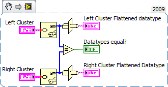
I was able to reproduce it and I show here as an oddity to force entry to the variant on the primitive flat string Variant.
Basically, if you have more than one cluster with content command to match the type and order wired directly to this function, it returns the flattened string which is first to each call. The wires must be wired without before converting to alternative, if you have points of constraint.
This only happens if you feed directly the input varying both and get the stress points. If you are using a variant is not the case.
I found that this occurs if the cluster is of type defined, and it does not occur for constants. I didn't try other controls. I'll be honest, I'm usually used to constrain to the Variant. I'll be more careful in the future!
----
so convert to first variant will solve your problem. In addition, if you leave the entry of the section name of the variant config openG write screw unwired, he will take the name as it is the research of the control, you did, so you need not the name of data Get there at all.
An excerpt from 2009. as - is equal to true. The bunches are each a dbl and a bool, but each FP different controls.
-
run a while loop in separate vi, minimize the window flashing
My apologies in advance for not including a VI; I cannot give it, cannot even provide screenshots.
I have a state machine base with a cluster of Boolean values that are analyzed in the 'default' State, the scan index = true determining the next State. All other States to return to the default state. The State of 'stop' stop the loop with a Boolean constant = True, located inside the structure case wired to the time entry conditional loop (all States have a Boolean constant False wired to it). Apart from the cases
statement, the wire connected to the conditional entry is connected to a Boolean indicator, ' Stop, in really. The time delay within the State of the machine while loop is currently set at 100 ms.
In addition to the 'State' shift register, the state machine has a "boolean" shift register. All States, except one, feeds the value passed the Boolean value through to the next State (i.e. wired directly from left to right the structure of the case). The exception is the State which inverts the Boolean value, with the output of the inverter transferred to the State following and also connected to a Boolean flag, 'Show the State', the
indicator outside the case statement but inside the while loop. All other States wire just the previous state of the Boolean value through the following State, unchanged.
In addition to the State of the machine while loop, I have a parallel while loop (scourge of the LV forums). All entered conditional loop is connected to a local variable to 'stop, really. " A True/False case in this while loop structure contains a Subvi in the case of True value. The Boolean value of entry to the case statement is connected to a local variable for 'Show status'. The Subvi, which is in the real case is to display the State of the
user.
The Subvi which provides status through its frontage runs a script in python via a 'comand prompt"vi. The necessary update to the python command send is ~ 1/second. Within the Sub - VI is a 1 second delay time after execution of the code.
It works but I'm doing some improvements with minimal impact on what I have.
Two cases of VI properties that relate to the conduct of the State Subvi (floating or default, modal does not at all):
1. with "Firm when previously closed" selected, the window switches VI (via the main switch VI) open and closed but when it is open there is the a second window flash that could cause seizures in some users.
2. with "closes when previously closed" deselected, the window remains open and it is difficult to tell the difference between the running state and is not running. In addition, the Subvi window will not be reduced for this option.
Is there a little invasive change, I have the code in force to stop a second flash described in #1 above and activate / deactivate the Subvi status window?
Thank you
Jeff
-
Merge two VI, a pass-through to another VI
Hello
It's more about asking a suggestion to ask the solution to a problem.
At the moment I have two independent VI
1st VI - acquire impulses in real-time, filter it, detect the peaks, take tiem difference between peaks, use this information to calculate a certain number of parameters that change in real time according to changes in pulse signal.
2nd VI - select a rhythm of breathing and guide the user using the fornt Panel bars and the audio output following a rountine.
Now I want to combine the two VI as the 1st VI processes the data and sends information to the 2nd VI. The loop runs a second apart, so data are discharged into a table in half a second.
The second VI will be, according to the data obtained form VI 1, either use these data to change the front bar and audio frequencyto guide user or it can use its own values.
The second VI will take the data from the 1st VI all a few seconds and then its own tasks of façade.
The idea is to create a system of biofeedback that guide the user (2nd VI) based on signals physiological user (calculated in 1st VI)
I have read the information on the parallel loops and how data is transferred between them. I have not yet implemented any of these and have little time in my project wish to get some suggestions.
I would like two front panels for that data collection and prcessing graphics are displayed on 1st FP and 2 user guidance. I do not know it can eb done using the 2nd VI as void VI. but do not know if this is the best way both of them to communicate.
Any suggestion is welcome.
Thank you
JAS
Preferably not. If possible, wire data directly in the Subvi if the connector pane. Since you want to that they act independently, I suggest using queues for each type of data and/or group. Queues can be referenced by its name rather than wiring directly to the Subvi.
-
Help for the reconciliation of table. Average cost
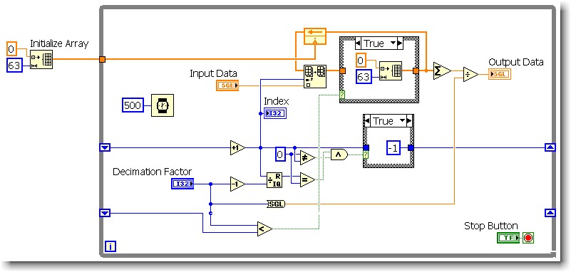
So this is my attempt to imitate a function block that we use in our standard converter software - "Decimation filter" which is nothing more than a running average / mobile. The sample size is adjustable to execution of 2 to 64 samples (decimation factor). I saw many topics on this and used to average around 4 large samples shift registers - but I wanted to be able to change the sample size without recompiling. I'm new to LV, there is likely a lot of better ways to do this.
I would like to have answered is linked to clear the table, if the decimation factor is set to a lower number than the last time that the loop executed. (The uppercase - false statement is wired directly by)
The math in the shift register: creates an array index that cycles from 0 to (decimation Factor-1). The index is then used to fill elements in the table (the rest being zeros). When the decimation factor decreases, I need zero external element in (former decimation factor - 1) (new decimation Factor-1) positions. So I tried various things, but the only thing that seems to work, it's the re - initialize the array. I think it's less than optimal.
I tried:
(1) leaving the tunnel of continuous wire output for the real deal and selecting the option 'use default if unwired' - thinking I'd get a table of 64 elements, of zeros. Doesn't seem to work.
(2) a constant matrix cable tunnel exit if this value is true. When I followed him, after a decline in decimation factor - the probe seems to indicate an array of elements, not 64 No. And I do not see how to specify the size of the array of constant matrix.
If I use this in my application it will run on a target of cRIO.
Any help much appreciated.
You already have your initialized table, why not use it? Wire your table initialized via if this value is TRUE. Or better yet, use Select? function.

-
Question of scaling of the FPGA 2009 PID.vi LV
Hey all,.
I have been using the PID.vi in the FPGA LV 8.5 module. I've updated for 2009, and the vi of PID is different now. Instead of taking values for the Kc I16, Ki, Kd, value, it now uses FXP 16 bit, with an 8-bit integer value.
I'm messing around with my host now, trying to figure out how to change the values correctly. I was using the "niFPGA ScalePIDGains.vi" in the example of "discreet use PID - R series. This example is the same in 2009 LV compared to 8.5, in what is still growing values at I16. How would you correctly scale values in the FXP 16-bit value that awaits the FPGA vi?
Thank you
Bones349,
Here is some information on the fixed-point data type. You can try to use To fixed-point Function to convert the data type of fixed point of various other types of data, or you can try the wiring directly in the PID VI I16, as it appears to do the conversion for you.
-
Monitor goes blank after windows XP starts.
After my computer Windows XP starts, the screen turns white. I can see typical splash screens and the windows icon, that my home screen. But shortly after so that files are always load, the monitor is going gray. It is still 'active' designated by the green light, but after a few minutes Hibernate mode.
I use a laptop docking station Targus USB Video to allow us to pass the mouse and keyboard between our PC and laptop. In fact, we use 2-monitor cables with this, one where the monitor is wired directly on the PC and the other of the docking station to monitor. According to the computer on which is being used, connect the right on the screen cable. The monitor works fine with the phone. I wouldn't believe the origin our problem since this only started happening in the last few days.
I also changed the cable to the PC monitor without change.
The PC had a virus or some type of software problem?
Can anyone help?
You have posted to a group of win7?
Connect the monitor directly to the PC to test (without docking station or any what vid/switches) & maybe update the graphics drivers on the website of the manufacturer NOT winupdate
Maybe you are looking for
-
Satellite P10: Need new power plug
Hello, I managed to break the PIN into the charging port on my satellite p10 series. Is there anywhere I can get this part. I have someone who can fix it on the Board but just need to know where I can get parts of Any help would be appreciated Thank
-
Newbie on Equium A200 (PSAE2) question
I recently bought the laptop A200-15i (Equium A200 (PSAE2)). Everything works fine, but I noticed that I was not provided with a master restore disk. I don't see any facility for the creation of a non more. The list of packages informs me that I shou
-
Qosmio F20: wireless keep disconnecting
Hello I have a problem with my laptop. He always cut after 2-3 min for the wireless network. I don't know what's the problem with him.My laptop is Qosmio F20 with WINDOWS MCEMy router is USR 9108 with security on the wireless network using WPA - TPK
-
Windows Media Player - real, 16:9 4:3 display
Any movie DVD wide screen is displayed as if it has black lines at the top and bottom. I use sub titles. The WMP 6.4 display correctly in full screen, but not mode can not display the subtitles... How did Microsoft have no interest in fixing it? VLC
-
Cannot download and install the update for Windows Vista (KB2481109) security
Up-to-date security for Windows Vista (KB2481109) and update for Windows Mail Junk E-mail Filter [March 2011] (KB905866) ideas? Error codes displayed are: Code 8E5E0147 Code 8E5E03FB But without any answers of MS Anyone able to help? Thank you very m