With an average of 10 channels of waveform separately
I've written a VI that takes input from 10 different devices then shows in several graphics and then saves in PDM. This works perfectly well. The problem is, on my PDM data, is saving 25 samples per second creating a file of long worksheet for short durations. Im trying to figure out how to reach an average of each channel independently (average 25 samples) and print it out every second, so there should be a 1:1 ratio between my timestamps and data, not 01:25 how it is now. Thank you!

Personally, I just averaged 100 samples you take. If this simple solution is to replace your table decimate (inside the square structure) with a Mean.vi. You will need to use a range of build with a single input to transform a table to write in the waveform (still inside in Place element Structure) of the average.
Tags: NI Software
Similar Questions
-
With an average of a spectral waveform and view / save
Hello world!
I am currently on a University project that consists on the use of Labview to obtain data and spectra of atmospheric plasmas using a spectrometer Ocean Optics HR4000.
After not not using Labview for almost a year, I managed to get most of my knowledge back and I managed to display the spectral waveform, that I expect to get. However, as this is a fairly simple design I get a lot of noise and I would on average it for a graphic display more smooth.
I looked into a lot of messages from the forum, but I couldn't really find what I was looking for.
I also had a problem when you try to save the data and Spectra: I can't find anything in the directory of my VI.
In the attachment you will find the current VI I'm trying.
Thanks in advance for your answers!
Jeremy
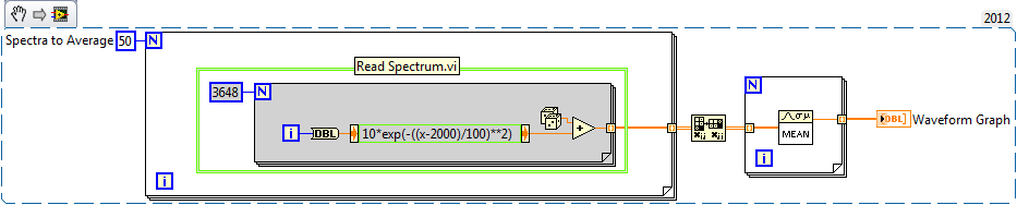
I wrote an example for you below. This is an excerpt from VI, so you can drag the .png in your diagram and it becomes code. Pretend that everything in the green box is your Subvi spectrum acquisition.
-Place the Subvi in a loop to run as many times as you like on average there
-Out of the loop For is a table 2D with individual spectra on the lines
-Transpose output, so individual spectra on the columns
-Enter the table another loop to take the average rank by rank (with an average of different Spectra togeter).
-Output is 1 d spectra average table
-
Covered wagon with an average of analog voltages DAQmx
I searched through screws, I can't seem to find something that will automatically average numbers of boxcar fed into it. I am trying to create a feature of my software that will allow the dynamic configuration of the car covered with an average of some inputs. I would like to avoid hard-coding tables which are filled/rotation etc etc.. Any help is appreciated
Thank you
If you use a Functional Global to store the values and call that VI of two different screws, you will access the same data. You could use two Global in the functional shift registers and use a selector to place / extract data from / to the appropriate shift register. Only VI call access one commune VI at the time, so one of the caller of the screw will be 'blocked' until the first caller is done. This does not usually work for data acquisition applications high speed.
You might consider using named queues instead of functioning overall. You might be interested in this thread on the forums of LAVA that deals with boxcar implimentations. You create a queue for each data stream and can perform functions such as "preview" queue to get all items without actually removing them from the queue. If you use a LabVIEW 8.6, there is a new feature called with loss of queues. You set an upper limit on the size of the queue and "lossy enqueue" allows to add items at the end of the queue. If the queue fills up, then the oldest data element will be lost.
-
generic calculations with changing the number of channels
Hello
I want to do some math basic with a flexible number of channels. The point is that I get an error if I specify strings that do not exist in my calculations. For example:
CCh("[1]/CNV",2)-CCh("[2]/CNV",2) + CCh("[3]/CNV",2)-...
I think that it should be possible to do this using a script, but you have no idea how to do it only with the calculator?
Thanks in advance
Jeremy
You can do this easily using the recoding for VBScript method described in the following KB:
http://digital.NI.com/public.nsf/allkb/B769AE10EDB656D28625692D00583166?OpenDocument
-
Problem with output 5VDC NI 9411 channel
Hello
I'm having a problem with output 5VDC NI 9411 channel. According to the specification of the module, it was stated that the module required external power from 5 to 30 VDC. Game of supply the module with the requirement of tension, I am still unable to get the output voltage of the output channels. Does this mean that the output voltage may be available depending on the program?
Thanks in advance,
Kind regards
Mike640
Hi Mike,.
Thanks for posting on the forum of National Instruments.
You should still be able to get an output voltage in properly feeding the NI 9411 and your external device.
If you don't have a power supply of 5V to power the external device directly, or if you want to simplify the cabling, you can connect an external power supply to the Vsup and COM terminals on the connector terminal block screw NI 9411 and connect the external device to one of the pins Vout + 5. If the external device is already powered, you have not need connect a power supply on the NI 9411 or plug the Vout of + 5 to the external device.
I hope this helps.
-
with an average of 5 minutes of data - is no way
I need average 5 minutes worth of data, save this average and then again on the next 5 minutes of data, with an average of this data block. I tried to use the average function pt-pt in LabVIEW, but who seems to take an average continuous market, I do not want. I probably read data once every 0.1 seconds, so I can not used stacked registers at offset, because it would be not very economical. I thought to build a table, but I don't know how to remove all the data at a time on average to it in an efficient manner, and more I'm stuck on the concept of re - create the table/clear the Board after five minutes of data has been collected, averaged and recorded.
Does anyone have a suggestion? I would really appreciate any advice or suggestions on how to go about it.
Keep a running total in a shift register. When your 5 minutes have expired, divide the sum by the number of samples taken, the sum to zero and start over.
-
Dealing with purge of one voice channel to another Podcast. Chaining aside?
I recorded a podcast with a new audio kit episode. 2 dynamic microphones in a blender, recorded on hearing CC via USB with a microphone on each channel.
Now I'm editing it I found that a speaker, Mark, is quite much stronger than the other, Ben, and Mark can be "heard" by Ben's mic.
CH 1 - Mark speaking loud and clear the voices.
CH 2 - voice gentler Ben. Crosstalk between Ch 1 is quite noticeable.
As a result, purge of Mark in Ch 2 creates an embarrassing mixture echo when he speaks, and Ben is not. If I solo Ch 1/Mark, her voice is nice and crisp with no echo. When Ben talks to himself, the mixture is also nice and crispy because it is not strong enough in the room to mic effect mark.
What is a good way to deal with this? I played a bit with chaining aside some dynamics processing (I'm totally new to side-chaining). It is 'ok', but it's a bit hit and Miss, in some cases when Mark and Ben call string active side Marc Ben DP, cut him too.
That explained everything well? Hard to explain something when I don't know the terminology to explain it is!
I guess every studio with 2 people or more on pickups in the same room must have this problem of "purge". How he usually treats? Next time I record, I think I'm going to try and move the microphones away from each other at first.
Post edited by: Ben Hutchings to add more details and correct a misleading title.
Well, chaining front side I think I might try a simple noise gate. Carefully put in place on the channel which is picking up 'the other guy' it might work for you.
However, if an "automatic" solution (door chain or noise side) does not work for you, and it could never be perfect - be prepared to go through and manually adjust levels manually. You will be surprised how quickly you can get with a little practice.
Long term, you're always better off trying to avoid this kind of problem at the time of registration. Simple things like choice of microphone and positioning can make a big difference, as can moving your speakers a little further out. Assuming the use of directional microphones, putting the microphones back to back to use dead spot in picking model... and mobile people a little father goes to use the "inverse square law' might well give you what you need without a lot of treatment.
-
What is after effects come with CS5 extended or should I purchase it separately?
What is after effects come with CS5 extended or should I purchase it separately?
They are completely separate products. Photoshop is just Photoshop.
Mylenium
-
waveform, with an average of results using labview to O-scope
Hello fellow engineers! I'm a first-yeargraduatestudent in CHEE at the University of Houston. Basically, I know nothing about labview. I am trying to program an application that looks like this - I collect a waveform of the signal of O-scope. This waveform does not change its characteristic shape. I need to find the wave form average of waveforms of N (100 for example). Thus, the slight changes (or noise) in the feature of form during the period mustbeaveraged out and I need to have a resultant waveform that represents the average waveform over a period. So, basically, I'm collecting the wave several times (for example 100) on a single period. The O-scope that I use now is Tektronix TDS 2024 B. It communicates with the computer via USB. The version of labview is 8.5. For now, I am able to communicate with the computer using our o-scope through labview. I already downloaded the driver of instruments of your Web site. It turns out that the program can give me only the average result I can get directly from o-scope manually. I need to have more say on average (100) using labview. I wrote a program that relies on the instrument driver that is downloaded on your website (for loop part is average, the waveform). The program that I modified and an instrument driver are attached. The program cannot be fully open, if the driver is not put in the right place in the labview (under lib inst.) When I run the program, the average waveform does not appear on the front panal and signal waveform file is not saved correctly. Is there someone can find where I did wrong and it develop for me? Because I barely know Labview, it will be even better if you can add an image or program that you have changed. I'm waiting for your creative ideas.
With the best regards,.
--
Weiye
-
with an average of streaming data
I take analog measurements on a module SCXI 1102C through a PXI for LV2009. I'm running the DaqMx Read 1 d Waveform to 100 samples per second in a while loop that runs every 45-50 MS, it means that I get about 5 data points per while the loop iteration. Even if the program is windows-based, it has a good amount of determinism built in. I now have to make a decision based on an average of 15 samples, preferably 25-50.
I can't slow down the while loop down because there are other channels in data that must trigger some things at the fastest rate possible in windows. I can live with the latency of 50 to 100 ms for the latter, but not the 500 ms I would get if I slowed the loop down to this new task.
Are the only two options that I came to use five registers with shift on the while loop, but I really don't like this idea. Or open the TDMS file while I write these data and read the seconde.25 block that I need a way to make a decision. Also seems to be a bad idea.
A third option, in my opinion, would be to place a Subvi who writes this string to five different functional space and constantly updates their creation of a buffer running. It seems not a bad idea, I just don't know how to implement it yet.
Any option obviously better that I'm missing?
There are two different methods that can be used. If the loop of writing runs more slowly that the loop of the acquisition, then the functional global is to keep a number of samples in it anyway. This allows more data work on when an average.
The other is to use a moving average. I have attached a VI that does this. It's a global functional on its own.
Rob
-
I use the outgoing/incoming analog DDK with the DAQ 6341 SMU map.
The examples, for example aoex5, show a single timer (method outTimerHelper::loadUI), but the example shows the DMA loaded with same size of vector data.
There is a comment in the outTimerHelper:
 call rogramUpdateCount, which implies that memory sizes different pad per channel can be used.
(the comment is: switching between the sizes of the various buffers is not used)
Nobody knows what should be the format the DMA buffer for data from multiple channels with different frequencies?
For example, we want a0 with a sinusoid at 1 kHz and a1 with a sine wave of 1.5 Khz. What looks like the DMA buffer?
With the same frequency for each channel, the data are interleaved, for example (ao0 #0, ao1 #0; ao0 ao1 #1, #1,...), but when the frequencies for each channel is different, what the stamp looks like?
Hello Kenstern,
Data are always intertwined since each card has only a single timing for each subsystem engine.
To AO, you must specify the number of samples that will be released to the AO. You also specify the number of channels. Because he didn't is that a single engine timing for AO, each AO will be channel will be updated at the same time to update clock tick. Data will be interlaced exactly as shown in the example because each channel AO needs output at each tick of the clock to update. The data itself can change depending on the frequency you want to copy.
kenstern wrote:
For example, we want a0 with a sinusoid at 1 kHz and a1 with a sine wave of 1.5 Khz. What looks like the DMA buffer?
With the same frequency for each channel, the data are interleaved, for example (ao0 #0, ao1 #0; ao0 ao1 #1, #1,...), but when the frequencies for each channel is different, what the stamp looks like?
In your example, you must come with an update rate that works for the two waveforms (sine waves of 1 and 1.5 KHz). To get a good representation of a sine wave, you need to update more than 10 x faster than your fastest frequency... I would recommend x 100 if possible.
Update frequency: 150 KHz
Channels: 2
Then create you stamps that include complete cycles of each wave you want to produce based on the frequency of update. These buffers must also be of the same size.
Buffer 1: Contains data for the sine wave of 1 KHz, 300 points 2 cycles of sine wave
Buffer 2: Contains data for the sine wave of 1.5 KHz, 300 points, 3 cycles of sine wave
You can Interleave them as before. When the data are performed through the ADC, they are out different sine waves, even if the AO channels are updated at the same speed.
-
With an average of readings of the oscilloscope
I have a virtual four-channel oscilloscope. I have spark and get values in a 2D array. I would like to the average of the five consequetive results. However, the program, I am changing is badly coded, I can't use shift registers. My only option is to store the values of the oscilloscope somewhere and after getting five of them by dividing by five.
I tried with tables, but I have no havw a lot of experience, so I couldn't do. What would be the best approach?
Thank you
Erden
Hi Erden,
a local variable is rarely the right approach
 (you know LabVIEW uses a DATA flow approach?)
Try this instead:

Two ways, with or without change of register...
-
If I replace the control with another why DAQmx create channel once complain a false claim?
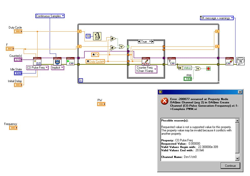
I tried to replace the frequency by another control in the example found here complete PWM:
http://www.NI.com/white-paper/2991/en
However, I get the following error message:

Possible reasons:
Requested value is not supported for this property value. The value of the property may be invalid because it is in conflict with another property.
Property: CO. Pulse.Freq
Required value: 0.000000
Valid values begin with: 22.300000e - 309
Valid values ending with: 20.0e6Channel name: Dev1/ctr0
Task name: _unnamedTask<10>
My wiring diagram looks like this:
If I cancel my change (i.e. I have remove the frequency control knob and turn it over to the control of the example, it works perfectly.) I get the waveform is displayed in the oscilloscope.
My goal is to simply use a frequency and duty cycle control knob. How can I achieve this?
There are two things to do.
What I think you did now changes the scale of the handle.
You will also need to change the values that are allowed to enter. You will do on the data entry tab in the dialog button properti.
Uncheck the 'use default', the Minimum value limits and Maximum identical to your balance.
Value "Response to value out of range" Coerce to both Minimum and Maximum.
I hope this helps.
Let me know if you have more problems. -
Hello everyone,
I have a question about signal average in labview. Please help me.
I have two entries of signals to my LabView code, one comes from a function generator (in saw teeth with a frequency of 10 Hz and amplitude of the 0.4V) and the other by a detector. For each voltage coming from the unit, there is a response of the detector so that I can have a graphic on my code that the vertical axis is the response of the detector and horizontal axes is the voltage of the generator (the graph is original linear signal from).
The frequency of the generator is of 10 Hz and I have 10 signals per second (as time passes, a lot of signals can be seen on the other). Now, how can I know LabView that update the chart every 5 seconds, what was on average 50 signals? In fact, I need to see only the final signal that is an average of 50 raw signals.
Your help will be really appreciated
Thank you
Soran
Hi Soran,
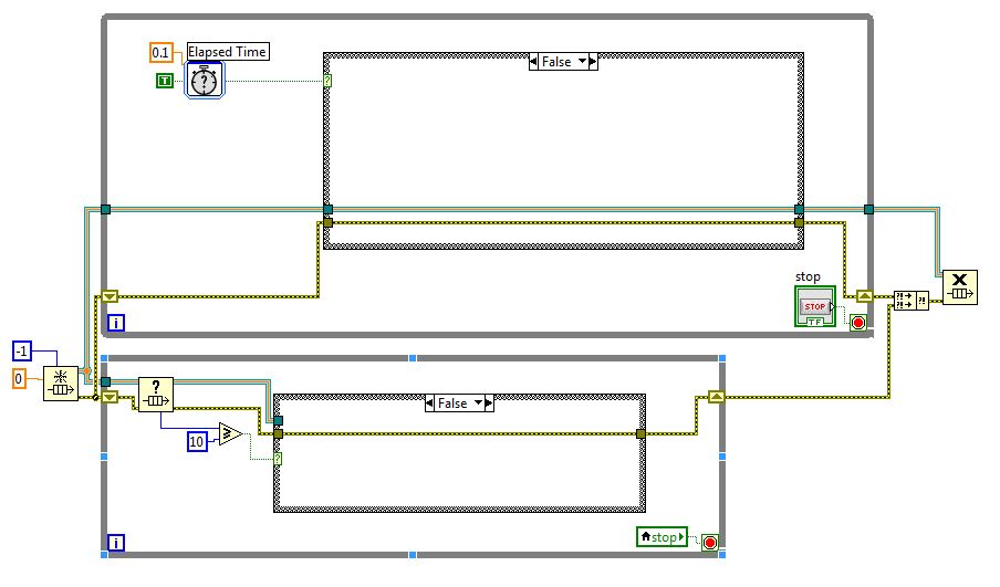
I think the problem is that when the time is up, you stop the program and draw the thing on the XY graph. Problem is that when you stop code, the graphic delete (of course there that shift registers not initialized that contains the value of your past last run results). The easiest way is to use queues via the architecture of producers consumers (http://www.ni.com/white-paper/3023/en/).
From the diagram below, you can see that I have 2 while loops. One is the producer where I store the values of the DAQ assistant in a queue while the lower loop is my consumer which I extracted the data stored in the queue. So for every 100 ms time will send the True value to the business structure that stores the value of the queue (you will need to play with the settings of the DAQ Assistant). If this is not the case, the producer while the loop runs the false cases indicated in the second screenshot. The consumer while loop, there is a queue Status.vi get that checks the State of the queues. As soon as there are 10 items in the queue, I find their (real case turns structure) which gives you an array of 10 elements. I have summarized the table of 10 elements and divide them by their size of table (10) and he draw a waveform graph. Otherwise, the consumer while loop runs the wrong case (meaning no evidence is found and allow the data to be buffered).
Just take screenshots above regarding your own reference. I'll leave the rest to you on how you want to adapt this concept in your code.
Hope that helps
Warm greetings,
Lennard.C
-
With an average using the "basic DC/eff' VI
I seem to end up using the "basic DC/eff" VI a little average my data to my DAQ system. However, I have a question about what's going on "under the hood".
Let's say, for simplicity I acquire data at 1 kHz into blocks of 1000 samples.
Thus, all the 1 second I push 1000 samples in the VI-DC/RMS database as a data type of waveform.
This means that the outputs 'DC' and 'Eff' will update at the rate of 1 second.
The question is, is "continuous" averaging? In the sense that if I was doing 'good' low-pass filtering (on average is just the same as the low-pass filtering) - say simple TREE with notches n - to the DSP, then the output of the filter would be updated at the same speed as data entry; That is to say. taps would be 'move along' the input data at the same rate as the input data passes through the filter. I'm guessing based on my above explanation that's not what's happening. Instead, the VI DC/RMS is on average an entire block of 1000 samples and then 'jump' 1000 samples along and doing the next block.
This is not necessarily a problem, but it is not not true low-pass filtering and I can image some scenarios where there might be artifacts because the moyenneur filter jump 1000 samples whenever it takes on average. I assumed that the only solution is to implement filtering in a loop of much higher speed and this could prove problematic in the higher frequencies of sampling.
Anyone got any ideas on that? I worry about anything?
Dave
Hi Dave,.
The 'average base DC - RMS' feature is designed to work only with continuous acquisitions, it will lift a warning is the signal is not continuous. When you open the function and examine the code in the function there is a Subvi with status information, which permits the function to continue the average of the previous data block.
For this reason, we provide a reset terminal if you need 'forget' the previous calculations.
Much of this is discussed in the detailed help on function, but still sometimes there hands dirty to know how the code works and review the code.
Concerning
JamesC
NIUK and Ireland

Maybe you are looking for
-
Tecra A4: suspend/shutdown/logout buttons missing
HelloI am running windows XP on a Tecra A4,sometimes and so far I have not found a rule, the buttons associated with the stop/suspension and logoff, on the start menu, are endangered, and the only way to close is the Task Manager. Any idea to solve t
-
C855 satellite - cannot change the FN key via Control Panel
HelloFirst of all sorry if my English is not perfect. I'm from the Italy. Bear with me. I have a satellite phone Satellite C855 PSCBYE.I formatted my laptop but there is no software Toshiba on this subject.So I downloaded HW installation and the Tosh
-
My time display has changed to military time and I can't reset it to normal
My recently changed time normal military time clock. I do not change it, and I can't find a way to reset to normal time.
-
Vista keeps close my sign in to LOTRO
I connect to the Lord of the Rings Online (LOTRO). The game begins to open. A message from Vista saying that the settings will change (for the game) and then it stops the game (does not allow further opening). So I have the same process all over aga
-
My dell 1545 is the "standby" and don't wake up mode
I have a del Inspiron 1545 and is in "standby mode" and is been like this for nearly three days the power lite turns on the fan comes in two seconds, but then it does nothing