Covered wagon with an average of analog voltages DAQmx
I searched through screws, I can't seem to find something that will automatically average numbers of boxcar fed into it. I am trying to create a feature of my software that will allow the dynamic configuration of the car covered with an average of some inputs. I would like to avoid hard-coding tables which are filled/rotation etc etc.. Any help is appreciated
Thank you
If you use a Functional Global to store the values and call that VI of two different screws, you will access the same data. You could use two Global in the functional shift registers and use a selector to place / extract data from / to the appropriate shift register. Only VI call access one commune VI at the time, so one of the caller of the screw will be 'blocked' until the first caller is done. This does not usually work for data acquisition applications high speed.
You might consider using named queues instead of functioning overall. You might be interested in this thread on the forums of LAVA that deals with boxcar implimentations. You create a queue for each data stream and can perform functions such as "preview" queue to get all items without actually removing them from the queue. If you use a LabVIEW 8.6, there is a new feature called with loss of queues. You set an upper limit on the size of the queue and "lossy enqueue" allows to add items at the end of the queue. If the queue fills up, then the oldest data element will be lost.
Tags: NI Software
Similar Questions
-
Generate an analog voltage with amplitude variations
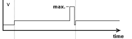
I want to generate a 0 - 5V analog voltage output that has a variable amplitude, as shown in the figure. The maximum voltage is 5V and low voltage a percentage of this, but I must not vary the amplitude during execution of VI.
With digital outputs, you are limited to two levels. Low and High. (1 and 0). Here are the outputs of the DIO lines as DC voltage levels. The two levels can be anything, but 0v is most commonly used for bass and 5v is used for the great. This is called (as well as some other features) TTL logic.
There are some cards that allow you to choose the digital voltage levels, but your all-in-one does not provide this functionality.
You could do something similar with digital, where you have only used the 0v and 5v levels.
You are absolutely right that software control timing is less precise than the timing control material, however, if you did a spot of digital output in this way and set it up to do the finished samples or continuous, it would use a material timing and would therefore be very accurate (in accordance with the specifications in the technical data of the device).
-
Problem with a precision of analog input on PCI-6111
Hello
I'm reading an analogue signal which varies from 0-11 V using a card of acquisition data PCI-6111. The signal comes from a Tube set (PMT) which is part of a microscope configuration, so it is very important that the resolution of the analog input signal be as wide as possible generate quality images. According to the data sheet for the PCI-6111, the analog input resolution is 12 bits, which should correspond to a sensitivity of ~2.686 mV for my voltage range.
To test this, I set up a task to analog input with a 0-11 V voltage range to read samples of an analog output, which I wrote a simple waveform. Since the 16-bit analog output resolution that I assumed that it would not limit the accuracy of this measurement. I have attached the VI I used for this measurement below. The analog input data are saved not truncated in a text file.
Analyzing these data, I found that the real input sensitivity is ~9.766 mV, corresponding to levels of voltage exactly 1126,4 and ~ 10 bits.
Is there a reason why the resolution of analog input is much lower that it is indicated on the card? What are some of the ways I could improve the sensitivity of this measure?
Best,
Keith
Sorry, when you mentioned the specs, I thought you already had them. If this did not come with your Board of Directors?
-
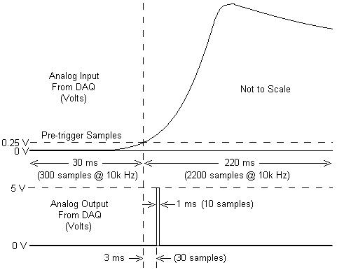
I am working with a combustion chamber and using a system of data acquisition (with the hardware OR SCB - 68) to read the pressure in the cylinder (such as analog voltage). I'm trying a pulse delayed, 1 millisecond to 5 volts of output once the pressure in the cylinder is high above 5 bar (which corresponds to an analogue voltage of 0.25 V). I would also like to record 30 ms samples before the trigger and 220 ms samples after the outbreak. The following image shows visually what I'm talking about.
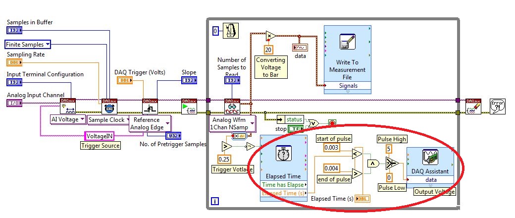
I created a LabVIEW VI (which is attached), but I keep running into 2 issues:
- When I run with samples finished after a period of time, I get error-200281which I don't quite understand.
- Using the Express VI 'Out of time' to keep time for the pulse I can not get a resolution of 1 millisecond, the pulse is not generated when I put the window between 0.003 and 0.004 seconds for high pulse (i.e. the resolution of 'Elapsed Time' seems to be too coarse).
I'm a beginner to LabVIEW sorry if my questions are trivial or my VI makes no sense, but I was stuck on this during more than a week. Any help would be greatly appreciated!
Thank you
Morgen
This isn't a good way to trigger a pulse.
Use a trigger DAQmx to send the pulse when your acquired signal exceeds 250 mV you specified.See this for DAQmx trigger:
-
is it ok to connect two outputs analog voltage in series?
Ok... I have a PS-210 FieldPoint... basically an analog voltage output 0 - 10V, 200mA per channel (with additional external power supply)... my question is... can I plug two channels in series? Love how I can put two AA batteries in the series... and then to double my blood pressure? and then check my two separate channels and the sum of the tensions would be assujettirait I have my load in?
Thank you!
No, you can't. The channels all share the common side of their outputs. If you've tried to hang them in the series, you have wind of short-circuit one output from the ground.
The reason for which you can do with batteries is that the tensions are floating. There is no common reference between the negative terminals of both batteries.
-
Hello
How acquire and store the values of voltage DAQmx?
I tried several code example, but they can't get the chart. I don't want to chart. I want to measure exactly the analog voltage values and record these values - as an excel chart, that contains the selected channels and voltage values.
What the example code that I can use?
My hardware is NI PCI-6251.
Thank you very much.
-
Get the duty cycle of DAQ to analog voltage input module
Hello.
I'm new to labview. I have an analog voltage input data acquisition module. I try to get the duty cycle of a square (generated from a function generator). What is the best way to go about this? When I use the vi to acquire an analog wave cyclical report, the values are incorrect.
Post your VI as well as real data of your signals so we can see what is happening.
Lynn
-
Trigger SW analog voltage CONT Acq & graphic
Hello
In the example Cont Acq & chart analog voltage SW Trigger.vi It seems to me that if specify you a channel that relaxation comes on, then it would be a hardware trigger is not a software trigger. Why do call it a software trigger work?
I PCI6071E I want to trigger by sending in a channel if a pulse (63). Wouldn't that considered triggering material? If that is an example for this available?
Also I'm not clear on what they mean by the parameter ' Amplitude/hysteresis window' in the trip parameters. Could someone explain this to me?
Thank you!
-
With an average of a spectral waveform and view / save
Hello world!
I am currently on a University project that consists on the use of Labview to obtain data and spectra of atmospheric plasmas using a spectrometer Ocean Optics HR4000.
After not not using Labview for almost a year, I managed to get most of my knowledge back and I managed to display the spectral waveform, that I expect to get. However, as this is a fairly simple design I get a lot of noise and I would on average it for a graphic display more smooth.
I looked into a lot of messages from the forum, but I couldn't really find what I was looking for.
I also had a problem when you try to save the data and Spectra: I can't find anything in the directory of my VI.
In the attachment you will find the current VI I'm trying.
Thanks in advance for your answers!
Jeremy
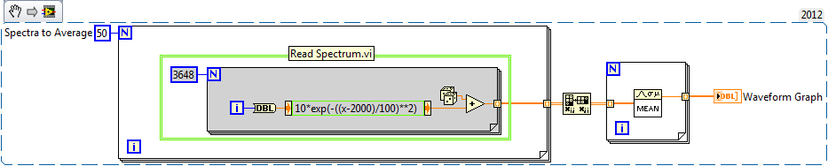
I wrote an example for you below. This is an excerpt from VI, so you can drag the .png in your diagram and it becomes code. Pretend that everything in the green box is your Subvi spectrum acquisition.
-Place the Subvi in a loop to run as many times as you like on average there
-Out of the loop For is a table 2D with individual spectra on the lines
-Transpose output, so individual spectra on the columns
-Enter the table another loop to take the average rank by rank (with an average of different Spectra togeter).
-Output is 1 d spectra average table
-
with an average of 5 minutes of data - is no way
I need average 5 minutes worth of data, save this average and then again on the next 5 minutes of data, with an average of this data block. I tried to use the average function pt-pt in LabVIEW, but who seems to take an average continuous market, I do not want. I probably read data once every 0.1 seconds, so I can not used stacked registers at offset, because it would be not very economical. I thought to build a table, but I don't know how to remove all the data at a time on average to it in an efficient manner, and more I'm stuck on the concept of re - create the table/clear the Board after five minutes of data has been collected, averaged and recorded.
Does anyone have a suggestion? I would really appreciate any advice or suggestions on how to go about it.
Keep a running total in a shift register. When your 5 minutes have expired, divide the sum by the number of samples taken, the sum to zero and start over.
-
is the AC adapter for example 463958-001 for compaq cq60 equipped with an output connector dual voltage? So I can't use the universal ac connectors?
Your laptop will accept universal power adaptors, you just want just to make sure it's a 65-W AC adapter.
The specifications of your laptop can be found here: http://goo.gl/b0r0r
-
Questions with more than 16 channels in daqmx
I've implemented a .VI (from the pieces of the help on the forum) that I use with the NI USB-6225 to collect and record anywhere voltages 1-30 or more 4-20mA sensors (pressure, linear voltage,... etc.). I tried to implement the .VI to make it user-friendly so that a person could name each channel, as well as to set the duration record and frequency (ie the number of samples). After the data were recorded, the .VI generates a time-stamped PDM file, a timestamped LVM file as well as a time-stamped LVM file for an average of all voltages on each channel.
The problem, I noticed that whenever I have more than 16 channels activated, the saved values for channels 17 and higher pressures are wrong. For example, the output voltages of 1 to 16 channels of a tension of 1.0 to 5.0 (which is expected) and 17-30 channels is negative or very small (0.100 volts). I know that the NI USB-6225 is working properly because I created a simple .VI which simply uses the DAQ Assistant ouptut 30 channels on a waveform graph and all channels of reading in the range I'm waiting (1.0 to 5.0 volts).
To me, it seems that there must be something in the DAQmx (as opposed to DAQ Assistant) I use my .VI who questions whenever I try to save more than 16 channels. I just don't understand enough of labview to understand what may be the cause of this problem and I was hoping someone could point me in the right direction
As you have not joined in the work programme, it is impossible to tell what you did differently. In this program, you do not specify the configuration of the inputs (simple nerve or diff).
p.s., The program is bad need of major cleanup. Keep the program to a single screen. Simplify.
-
NEITHER 9234 with quasi static analog voltage
Hello
I have a NI 9234 (4 channels + / IEPE 24-bit 5V) attached to a chassis cRIO module. This module is ideal for accelerometers and microphones where the tension is in constant evolution (ie; measures of variation rates).
I also have a module OR 9237 (4 channels 24-bit full-bridge module analog input) attached to the same cRIO. This module is ideal for measure variable voltages of strain gauges (quasi static and dynamic loads).
The attached graph shows the two channels, collected synchronously, but as you can see the (red trace) cell breaks down (as it should), but then drifts back to zero on its own, when in fact it should remain low just like the extensometer is beam. After all, the two sensors are physically secured.
Q1: Would that have something to do with AC/DC module 9234 internal coupling?
Q2: Is it really possible to collect "quasi static" ongoing tensions by using a NI 9234 module?
No explanation as to why this occurs, or if there is a way to remedy this would be appreciated.
Kind regards
Andreas
Coupling AC/DC must do a lot with your question. In mode AC voltages static will be fitered outside and the 9234 measure indeed only change voltages. In DC mode, the voltage goes directly to the AD converter and you can also detect static tensions.
A minute of Googling gave me the answer, this load cell electric piezo can measure dynamic changes, as any charge will escape the path the lowest resistance and the signal will go to zero after a certain time. I guess the other device you were using higher internal resistance (which is relatively low on the 9234), so it takes more time to what he flees, but he also took on the picture you attached your second try.
Here you can find more example under the title
"WHY ONLY DYNAMIC FORCE CAN BE MEASURED WITH SENSORS OF POWER PIEZOELECTRIC"
http://www.PCB.com/techsupport/tech_force
Andreas Jost
Technical sales engineer
National Instruments
-
Blocking of blue screen with the analog voltage (WinXP, PCI-6251)
Hello
I'm looking to solve a problem of blue screen with my measure blocking
application, which I am developing with C++. Blocking seems manifest
a little random after a variable amount (500-50 000) of voltage analog
measures. My application needs to make a huge amount of these digitally
trigger voltage measures after a certain period of time, and I'm using a
unique
task to do. The task is stopped and started after a single measure
is
which is done around 10 000 - 100 000 times per second. For this
because I do synchronized with the PCI-6251 map data acquisition and
one
Ztec oscilloscope card. It seems that the probability of blocking could be
associated with
the frequency of measurements of voltage that I perform.The
the app itself is multithreaded, but I'm blocking concurrent access
TO
the card with lock - all access to the card are behind a single mutexlock, so simultaneous access is blocked. In any case, all data acquisition
access
o the map is initially a single thread, which is dedicated to the acquisition of data
operations.I also did stress tests with Ztec scope map, which does not
result
in all the problems. I also disabled in order of acquisition of Ztec map data
TO
Make sure that it wasn't the card scope, the origin of the problems - the problem
persistent, so this seems to point towards the direction of the nidaq map.The deadlock appeared when I used the original supplied with drivers
the
card. I installed the latest drivers (removed the device from)
' Windows
Device Manager and your application Measurement & Automation, reinstalled), but the blue screen still appears.Blue screen gives me a few debug data, but it does not mention any
files .dll or something that would be of course point to a specific file (driver). I enclose at least partially matching code snippets.
Hello again! I've been in contact with a local support person, who suggested that I have use DAQmx_Val_FiniteSamps instead of DAQmx_Val_HWTimedSinglePoint. I don't have any other changes, but this (see below) and the problem disappeared, so this seems to be an acceptable solution, because I don't see at all why not do this way. (Thanks Henry!)
DAQmxErrChk (DAQmxCfgSampClkTiming (task_reader, NULL, 100000.0, DAQmx_Val_Rising, DAQmx_Val_HWTimedSinglePoint, 1));
DAQmxErrChk (DAQmxCfgSampClkTiming (task_reader, NULL, 100000.0, DAQmx_Val_Rising, DAQmx_Val_FiniteSamps, 2)); -
Helps with 7852R input analog voltage measurement
Hello
I'm trying to measure three signals of tension off a QPD, the three signals are connected to the IA the SCB - 68 and then I used the example of vi to acquire analog inputs with FPGA R in the finder of the example. However, I make a range of very large numbers. I don't know how to convert these volts or what are these numbers, units... etc.
Any help with this, please?
Thank you
Hi Biochemist_MU
Please take a look at the forum post FPGA of analog input and output scale. It deals with the scaling of the R-series cards.
Hope this helps and let us know if you have any other questions.
Maybe you are looking for
-
How can I get rid of the private browsing page when you open a new private window?
When I opened a private page of private browsing navigation appears and says this: Private browsing Firefox don't remember the history of this window. In a private browsing window, Firefox will retain all the history of the browser, search history, d
-
How can I remove Apps from my iPhone I want? Center for example, Stocks, booklet, etc. I'm beyond the age where all of a sudden, I to the great never, want to use it and I hate the mess.
-
Editor not found disk image app
Cannot open files.sparseimage sure, I created a few years ago with OSX... Last opened last year. Suggests the opening with diskimagemounter.app. However, the file does not open and I can not find diskimagemounter.app Who kidnapped ElCapitan, or befor
-
USB not installed correctly, print USB media, mass storage device USB Composite device
I am running XP and I get these 3 messages peripheral USB Composite USB and USB Mass Storage Device not installed correctly print media. What should I do? Thanks for any help.
-
HTML5 canvas, animated during a cursor
Hello everyone, my name is Etienne Deswattenne, I am a beginner flash of France so I apologize for my poor English, my question is this, how can we change the cursor to a symbol of the scene when the mouse is on another symbol? I have a 'this' proble