2 different Topologies of PXI - 2503
Hello
I use CVI 8.1, MAX 4.5 and switch Exec 2.01, Wndows XP2 to the following situation.
I had a previous (only 2 x 24) topology for a PXI-2503 switch, with its respective test program.
For my application, the Configuration of the previous switch is called LUN, consisting of DEV1_ivi.
For my next test for a different target program of the UUT, I had changed the topology PXI - 2503 DEV1_ivi to double 2 x 12 opening switch BC02 and separating the group 0/1 group 2/3.
This new configuration, called PSTESTER, works very well.
But when I got back to the old test program that calls the original called LUN configuration, the program execution caused many errors "could not connect..." ».
Review of the DEV1_ivi, shows that the original LUN is now set for a double 2 x 12.
The question is how to configure Switch Executive to keep the configurations of respective switch for more than one test program.
I hope I included enough information.
Scott Youngren
Jason
Thank you for an excellent response. I thought that it was a "logical" explanation I went to the MAX to see if I can rename or reconfigure.
However, I can't find exactly how to set up. I'll have to find a tutor to show me, step by step the mechanix of MAX.
Thank you
Scott Youngren
Tags: NI Products
Similar Questions
-
Problem reading the PXI-2503 channels above 23 in mode 1 wire 48 x 1 Mux on Linux
I can't get the above relay stations 23 in mode 1 wire 48 x 1
% nilsdev | grep 2503
OR PXI-2503: "Dev1".The topology is set on "2503/1-Wire 48 x 1 Mux ' via the following API, using the 'Dev1 '.
DAQmxSwitchSetTopologyAndReset (device, topology)
In theory this means there are 48 relay individual that can be read, however, fails the following:
SwitchName = "/ Dev1/ch47.
DAQmxSwitchGetSingleRelayPos (switchName, & pos)
The error returned is:
DAQmx error: relay name is not valid.
Relay name: ch47State code:-200202
who is
#define DAQmxErrorInvalidRelayName (-200202)
I can't get the relay station for foregoing relay 23 (/ Dev1/ch23)
Which is the expected behavior, or is there a hardware or driver problem?
When you use this switch in "1-wire" mode, we break essentially each (+) / (-) pair in their own channels. Since this topology uses switches bipolar, only throw which individual terminals cannot be activated independently, another switch is introduced in order to decide which side of the switch is consulted at this very moment, (+) or (-).
Instead of having 48 simple jet unipolar or bipolar, we have 24 bipolar single jet and two-way to decide what polarity we are referencing a single pole. You can still use this topology in mode 1 wire 48 x 1.
To switch manually using relay DAQmx controls, you need to specify the channel switch and polarity as Maggie mentioned. When you call ' DAQmxSwitchConnect/Dev1/ch47/Dev1/com0', the driver knows that he has to close the relay 24 ch in more 'HLSELECT' AND "1WIRE" route only positive (effectively ch.47).
The document NOR switches help contains a more detailed explanation of the topology if you access devices > NI PXI-2501/2503 >
1 wire 48 × 1 Multiplexer topology.
-
OR TB-2605 terminal block for the NI PXI-2503 relay card PIN GND interconnection?
I use the relay Board NI PXI-2503 and the NI TB-2605 terminal block to impliment some of interconnections, my question is on the Terminal it is a GROUND terminal on the GND PIN. What electric pins or card background basket or internal relay Terminal this 'point' interconnection to?
Hello gene01,
I don't directly know what this PIN connects to. Following the trace, that looks like it is connected to the mass of the chassis as the 2503 itself does not have a grounding pin. I have this will confirm for you, but is there a specific reason for your application need you to do this?
-
Hello
does anyone know the number of K-related relay relay channels? I can't find it in the documentation.
THX
Wolfgang
Finally I do the job to measure the relay by hand:
K0... 23 = CH0... 23
K24 = BC01
K25 = BC23
K26 = BC02
K27 = CJS
K28 = 1WIRE
K29S = HISELECT
K30 = AB0
K31 = AB1
;-)
-
How long does take to load a file of FPGA bit running? Can they be exchanged at runtime?
Hey this is great, then, what is the start of the actual application to the start time of application of the load to the load? It is milliseconds?, seconds? Thank you
Jon
-
How to control NI 2503 PXI using labview?
Hello
I am vishal.
I have a job where I have to monitor the temperature of the various components.
LabVIEW platform is used to make a software that takes the output of thermistor through NI PXI 2503 multiplexer and converts it into digital
using or pxi5152 digitizer.now I have to control the two instruments of this and take values of the digitizer.
but the problem is that I don't know who you screw to control these instruments, because I do this first time.
I just know that the NIDAQmax screws can be used, but do not know how to use it.
Please give me a little early to make this program.
Thank you.
You can find this useful: combined with the switch Modules OR PXI high-speed digitizers measures. Basically, OR-Switch is used to control the multiplexer.
-
Degraded signal: PXI-2501 1 wire 48 x 1 w / TB-2605
Dear friends,
I have a PXI-2501 configured in 1-wire 48 x 1 w / a TB-2605 terminal block. My goal is to move analog square waves generated with a PXI-6259 to a Bank of several LEDS. Last week I posted a question about the wiring of the TB-2605 and wired my block according to the jpg (attached below), I received. Unfortunately I'm having a degraded signal once routed through the switch... Very dark LEDs as opposed to very bright cases, I connect directly to the channel of the PXI-6259 AO. My first thought is that there is a bad connection GND somewhere in my wiring. However, before you disconnect the wires and hunt this grimlin with the voltmeter, I would like some consensus of the other members on the diagram below. I'm wired up properly?
Thank you
Zach
Hello Zach,
What features of the PXI-2501 make it suitable for your application? Have you considered using a different switch? The PXI-2503 has the same 48 x 1 1-wire topology and can be used with the TB-2605 terminal block. It's spec'd path resistance is < 1="" ohm="" and="" bandwidth="" is=""> 10 MHz. The PXI-2503 using electromechanical relays, so this module has a life expectancy over relay and a rate of slower cycle compared with the PXI-2501.
The PXI-2503 might work best for your application?
Chad Erickson
Switch Product Support Engineer
NOR - USA
-
Wiring question: PXI-2501 1 wire 48 x 1
Dear friends,
I need wiring help. I have a setup of the PXI-2501 for 1 wire 48 x 1 with a block of connection TB-2065. I have an analog signal entering the block I want to switch between 5 different LEDs. The incoming analog signal has two sons (positive & GND), and my Bank of LEDS has 6 wires (5 separate positive & a shared GND). I have reviewed the documentation section 'NI Switches Help' 'topology, NI PXI-2501/2503 1fil 48 × 1 Multiplexer', but he has not quite figured it. Can I connect my two ground wires and then connect the rest like this?
analog input
+ 1-> the Terminal 27
output LED Bank
+ 1-> terminal 67
+ 2-> 66 terminal
+ 3-> terminal 65
+ 4-> terminal 64
+ 5-> terminal 65
Also, should I be connecting GND wires on the block somewhere instead of themselves?
Any help would be greatly appreciated...
Thank you
Zach Barnett
Hello Zach,
Try to move the analog input + 61 terminal connection. You can a) connect your two ground wires or b) can connect the ground wires to the TB-2605 terminal block.
The image below shows the resulting configuration if you connect the wires to the Earth to the terminal block:

I hope this helps!
Chad Erickson
Switch Product Support Engineer
NOR - USA -
Maximum run times for 2536 PXI
The maximum manual user work time (page 3) is listed as Mrs. 16 it's a typo right? It should be right 16us?
Hi AbandoningCausality,
It seems that it is very likely typo. For reference, the 2536 uses the same material as the 2535 - it's just a different topology. Thus, the maximum work time must be the same 16us reported for the 2535.
I went ahead and filed a request for Corrective Action in order to update the data sheet. This request may be followed by the number 589816. Thank you for bringing that to my attention!
-
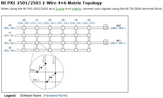
Resistance measurement using PXI2503
Hi, I am looking to understand how PXI-2503 measure resistance of 2-wire matrix 4 * 6.
and I tried several different configuration on my board but I couldn't receive the correct value of the resistance.
Software:
I use the example of LabView8.5 (niSwitch DMM Scanning.vi synchronous switching)
My scan list of entry (c0-> r0) under the switch
between 10000 and resolution 100 m under the DMM
Material:
I tried several set upward,
1. I put a resistor between C0 + AB0 + and r0 + AB0 -; and - c0, r0 - connect to GND, (this configuration gave me some graphics but no resistance)
2. I set the resistance between c0 +, r0 + and AB0 + (they connect) and c0,-r0, AB0 - (but it gives nothing.
my setup is bad? why I could not receive any resistance...
Thanks for any help
Hi Newer104,
The problem may be that the analog bus relay is not closed. Please refer to the following image and note that the ab0 relays must be closed to create a path between the rows/columns and the analog bus.
If I understand correctly, then I recommend placing the resistance between c0 + and c0 - and create the entry list of scan to the following address:
R0-> c0 & r0-> ab0;
Let me know if this solves your problem. Best regards!
Chad Erickson
Switch Product Support Engineer
NOR - USA
-
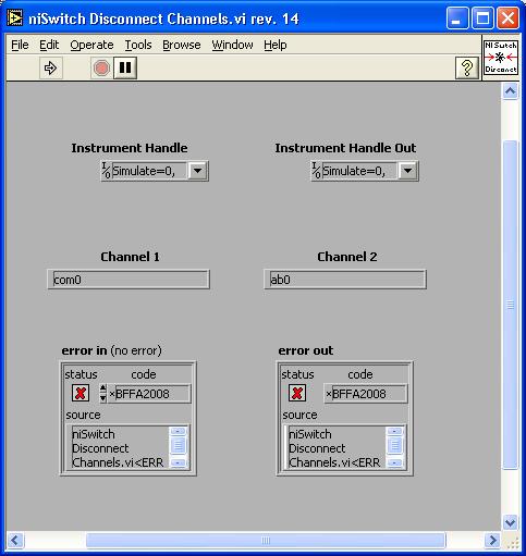
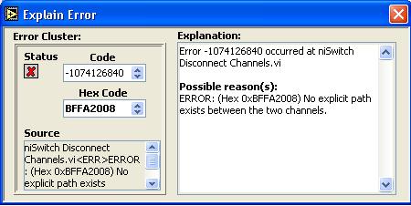
Hello
I work with the PXI-2503 card and work with someone of another code and I was wondering if anyone can guide me on this issue in case of problems. I don't know a lot about the physical interface, but I'm learning.
I have this error in my code.
When you use the OR-SWITCH drivers, you must make sure that there is an explicit path established between the two channels. This will not happen if the referenced channels are on different devices, check for this as well as check the exact name as it is implemented in a position and Automation Explorer.
-
WDS Airport Roaming vs vs Extended Network
Hello friends,
In a roaming network, all airports have the same wireless network name and wireless security settings. If I'm not mistaken in WDS also the same rule should be followed. Is also applicable to a network of Airport Extreme Extended (1 main base station connected to a broader base station)?
If this is the case then a user can move freely between these extremes of the airport with the same user name and password in any scenario 3. So what is the difference besides the AEs interconnected via ethernet and wireless in 3 different topology?
Thank you.
In a roaming network, all airports have the same wireless network name and wireless security settings. If I'm not mistaken in WDS also the same rule should be followed.
It is basically correct. Routers for Apple, there are three types of networks "scopes": 1) expanded that using wireless connections between fixed stations, 2) Roaming using connections between base stations, & 3) Wireless Distribution System (WDS) wired. WDS uses also all wireless connections.
The first two replaced WDS that was designed to be used only with the old base station 802.11 g. He has a major advantage. You can extend a network in a series as employed the use of a "main", "relay", and "distance" base stations. This feature is not embedded with the new models, elongated or Roaming.
Is also applicable to a network of Airport Extreme Extended (1 main base station connected to a broader base station)?
For the most part, Yes. The extended base station that's exactly right and the extension of the primary Wi - Fi network. So it would have the same network name and use the same type of security and password.
If this is the case then a user can move freely between these extremes of the airport with the same user name and password in any scenario 3. So what is the difference besides the AEs interconnected via ethernet and wireless in 3 different topology?
The main difference is overall performance of bandwidth of a Wi - Fi. Maintaining an extensive network using wireless connections only requires treatment of additional network traffic. This overload can reduce the bandwidth available to normal wireless traffic. This problem does not exist with a roaming network.
The other problem with a network extended wireless all is loss of bandwidth. Each added to the extended network, base station reduces overall bandwidth almost in half. Again, this is not a problem with the network of mobile type.
Finally, with a network extended wireless all base stations which extend to extend the hand to the same bandwidth it receives from the hand to this place. So the wireless clients connected to one of the extension of base stations will produce ever and when then are connected to the main.
-
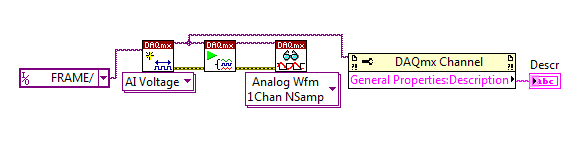
Properties: General Description of the channel
Hello
I am trying to identify my different input channels PXI I use and I would use the ' General Properties
 escription ' field to do so. The problem seems to be really simple, but I can't find how to write this field...
How can I change it? It always generates empty when I put a description in the constant channel VI or in the channel to create VI.
Thank you
Oscar
Hi Oscar,.
To write to a property in LabVIEW, you will need to click with the right button on the property node, and then select 'change all to write '. Using this property in write mode, a description for each channel can be set, which can then be extracted using the property even in playback mode.
See the screenshots attached for reference.
Kind regards
Tom - S
MEng (Hons) DRESSED
Technical sales engineer
National Instruments -
[HELP] NOR error of MAX and locking of the...
I have a NI SMU 1062 q and NI SMU 8135. Windows 7 Professional 64 bit installed.
I removed all the software OR using the control panel and then installed NI Developer Suite 2012. As part of the installation, the following has been installed:
NEITHER Developer Suite Core
Option deployment on FPGA (excluding the Compilation of Xilinx 10.1 Tools)
Automated Test option
I2C & SPI
NOR Serial + VISA
When I start OR it MAX errors with an exception. If I keep it then crashes. All menus are gray! He worked (with error), but now it crashes completely.
I have attached the dump file and log.
Also in the basket are:
PXI-6509 DIO card
PXI-7953R + 5734R DAQ + FPGA
Controller USB CB2-1-PIPE
PXI-2503 switch
PXI-4070 DMM
OR PXI-8430/4 RS - 232 card
It worked in the end.
The PXI chassis came pre-installed with a few cards that we had ordered. I think that NEITHER installed the drivers for these cards (probably more by 2012). Then, I removed all the software OR in the Panel and installed NI Developer Suite 2012. I think the drivers clashed. I did a restore complete system image to disk and re-installed NI Developer Suite 2012 and it was fine.
-
I'm having a problem with the help of EVS. I use LV 8.6 (impossible to pass to 2010 at this hour, must "make it work").
I used before shared variables with a GUI and PXI, but my setup is different now:
PXI (called target) that "speaks" to the different controllers via Modbus TCP/IP. Separate interface for PXI PC to provide a user interface (called my host).
I ran across messages spoken by calling the library method to deploy in the first level VI of the application. I want the PXI to deploy variables shared, because it will run constantly and the PC is optional. "Manually" transfer the shared variable library, in this case called the NetworkVars, for PXI so the PXI application can find? PXI will run independently once the program is fully developed.
I have used Labview for a long time but have never had to do a lot with networking and sharing.
Thanks for any help.
I ended up upgrading to Labview 2010 and now everything works as it should. I will mention that it was a complete horror show trying to upgrade... including duty reload WinXP on my development computer, because the files have become corrupt. Now, I have to charge a ton of programs, at a later date, because they are there but are not related. Fun stuff.
Thanks for all the help.

Maybe you are looking for
-
HP Pavilion P7 - 1254 PC: replacement of the electric cord and use
Moving to the Italy and take advantage of my desktop HP Pavilion P7 1254. Card said 10A 125V. Can I buy a spare with 120-240V power cord or I'm screwed?
-
Windows Mail termination errors
I use Windows Mail to connect to AOL Mail (using Windows Vista, the outgoing mail SMTP to . AOL.COM Port 587, Incoming Mail IMAP . AOL.COM port 143). I keep getting the following errors (on all differect records) and it makes it extremely difficult (
-
Hello Got a bitter ebay seller sent hordes of fraudulent emails - I read that it is possible to block this address but when I try to follow the advice I've seen on youtube - I go to than any other because when I sign in windows live mail is no GEAR i
-
RoboHelp 2015 responds very slowly
First of all, I'm sorry if I've got this post in the wrong category, but it seems that the General category of RoboHelp has been removed.I recently upgraded from RoboHelp 11 to RoboHelp 2015 on my Windows 2008 computer. I installed the available upda
-
How can I change the numbers in a numbered list
Work in Acrobat Pro ms, Windows 10I have a numbered list that I'm trying to change. I deleted one of the numbered list items and now need to change the remaining numbers so that they are all consecutive. While in PDF Edit I can change the text using