5154 PXI trigger on the external input
I use a PXI-5154 and want to change my previous program to trigger the external source. I'm feeding the external source from source to V 2.5 and it seems to trigger fine. However when data acquisition the vertical range of the oscilloscope will 5 V which is too high as to my request I acquire in the millivolts range. I tried to show the vertical range of the channel I acquisition, but although I put it as the active channel I get the following error:
Error 1074118616 has occurred to the property node (arg 1) in PD_measurements_v11_test.vi
Get a base attribute value channel failed because the channels interviewed have different values. Please specify a channel when you query a string based attribute.
I enclose you a printsceen of the relevant part of the code.
Kind regards
Karavellas
Dear Tunde
I managed to make the changes you suggested and the works of the example. I'll look in my code and see what the problem is. I'll get back to you if it has been fixed in my code or not.
Tags: NI Products
Similar Questions
-
Original title: external recording
While trying to record music on a software, connect the external input jack is
not to cut his computer system. Thus the external player unit is not recorded by
the continuous computer but the record of construction - micro. With the help of windows 7 on a dell computer
laptop.
Seems that you can set with precision in the application (whatever it is) where to get sound input or configuration in the audio to enable driver software disabled the internal MIC (manually each time, or automatic if the driver has this feature.)
Basically - you must look in the configuration of your audio device (third-party drivers) and/or the configuration of the 'software' you are trying to use to "save the music". -
Apex - with the external database audit trail
I'm currently installing a primitive audit trail that allows me to record data, create users, update, update user. I currently have 3/4 but I can not get the user name in the database like V ('APP_USER') is at the top and the database in Oracle 10 G elsewhere.
Suggestions or alternative ideas?
f1f7a787-7f56-4451-8300-5a9a0215226b
If v() and apex_application.g_user are not available in the trigger on the external database code.
But the external database package variables and procedures are available on the database running APEX.
What I would do, is to create a package with a package variable that will contain the user of the apex. (in the external database)
Then, in the application definition > session database > initialization code PL/SQL defined this package to the apex user variable.
Clear the package again variable in the cleanup code.
Using a package variable means that the value is aviable at the session of entire database but not outside the East.
Apex every page load or submit and load next page is a database session.
Now the package variable will be set when a user of the apex and the null value when there is a database user.
Using an nvl around the package with user variable as an alternative, will give you the user apex when the action was made by a user of the apex and the database user is not.
Nicolette
PS change your handle or at the signing of all least your post will result in a more friendly welcome message.
-
The original loop iteration after receiving the trigger of the PXI-6652 pulse
Hello world
I apologize if this has been answered somewhere else, but I'm having a hard time finding examples and tired after a long day of work.
in any case, I use a PXI chassis with a PXI-7854R FPGA Board and module synchronization PXI-6652. I have the FPGA biphasic pulses being generated at 8 analog channels. I want to be able to do is to send a trigger (say at 1 Hz) for the PXI-6652, which begins at the exit of the biphasic pulse on the FPGA. I'm running the FPGA through a host program as the variables on biphasic wave will change based on the current experience.
So, in short, I was wondering how to generate a trigger of the PXI-6652 pulse and then use this trigger in a host of VI to start an iteration of a loop. It seems simple enough, so any help would be appreciated.
Thank you, and I can post the code tomorrow if necessary.
To answer your second question, Yes, the driver NOR-SYNC 3.3 is available for download and use with LabVIEW 2011.
As far as use the PXI-6652 to start the acquisition on an FPGA VI, we have enough good examples provided with LabVIEW that will show you how to proceed. To actually generate a trigger with NO-Sync, there are several examples in the Finder for example of NOR (help > find examples) which send a trigger one of the PFI lines to be used with the other modules. You can search for OR Sync and they all appear here. You need this driver installed first before you see anything, however.
Also, if you look through the viewfinder of the example under Hardware Input and Output > R Series > FPGA Fundamentals > triggers and guard dog, you will find an example of triggering good enough it for use in your FPGA code.
This example uses NO-Sync to trigger a device of the M series, which is not relevant to what you are doing (he uses DAQmx), but there is a very good example of generation OR-Sync trigger here who I think can help.
-
PXI-6071e offset drift on the analog inputs
Hi, I have three cards PXI-6071E, sitting in a PXI-1042 chassis that is controlled by a computer with windows XP. The 6071Es are connected to the SCB-100 break out boxes that are wired to a pannel of BNC female Panel Mount on twisted pair.
I noticed that all of my analog inputs will drift around-10 V to + 10 V if they are not connected to what whether forcing them to a certain tension. This has always happened. We also see a bit of crosstalk between channels. For example if I open a panel of test in the measurement and automation Explorer I can watch the voltage read on the drift tickets through their full range, and alteration of the signals on nearby channels will appear on the channel, I am able.
Is this just standard behavior and to predict? Is there something more I could do to minimize this drift and crosstalk? I am trying to reduce noise in my system so I figure optimize my DAQ could not hurt.
Thank you
With nothing plugged into the catch to high impedance, drifting you see is quite normal. The front end of the circuitry builds up a charge, crosstalk is proabably due to the multiplexer input (did not check but I think that the 6071 has a) transferring the load to the other channels when they are analyzed.
Search the Forum of ghosting, you will find related discussions.
-AK2DM
-
input analog trigger on the door of the meter to measure the frequency of generation
Hello
I want to measure a frequency on the analog input, but it doesn't seem to work.
I'm trying to work with DAQmx with the use of the ansi c standard.
The first step, I've done was acquiring information on the analog input. With the use of a simulated device, it shows a sine wave on the entry.
My next step is to generate a trigger for the meter signal, but this doesn't seem to work.
I don't see how it is possible to connect the trigger on the entrance to the analog meter.
For the creation of the analog input and relaxation, I use the following code:
DAQmxErrChk (DAQmxCreateTask("",&taskHandle));
DAQmxErrChk (DAQmxCreateAIVoltageChan(taskHandle,"Dev1/ai0","",DAQmx_Val_Cfg_Default,-3.0,3.0,DAQmx_Val_Volts,NULL));
DAQmxErrChk (DAQmxCfgSampClkTiming(taskHandle,"",10000.0,DAQmx_Val_Rising,DAQmx_Val_FiniteSamps,1000));DAQmxErrChk (DAQmxCfgAnlgEdgeStartTrig (taskHandle, "Dev1/ai0 ', DAQmx_Val_RisingSlope, 0 '"));
For the creation of the meter, I use the following code:
DAQmxErrChk (DAQmxCreateCIFreqChan (taskHandle1, "Dev1/ctr1", "", 1 January 2000, DAQmx_Val_Hz, DAQmx_Val_Rising, DAQmx_Val_LowFreq1Ctr, 1, 4, ""
 );)
);)I hope someone could give me a hint.
I also tried the examples that come with DAQmx but well I know this are only examples to counter with the help of the digital inputs.
Thanks in advance.
Hello
You must use the exit event of comparison at the entrance of the meter. Change this property after the configuration string function.
DAQmxSetChanAttribute (taskHandle1, "", DAQmx_CI_Freq_Term, Dev1/AnalogComparisonEvent);
Kind regards
Bottom
-
How to read the analog inputs of one Board of R for (PXI-7851R) series
You can guide me please with the steps for reading of the analog inputs of a series a. card I use as the target fpga PXI-7851R.
Have you looked at the examples provided with LabVIEW? There are examples showing how to read the analog inputs.
-
Are people capable of reproducing the following, or is it just me?
Problem:
Impossible to activate the agent of property entry for an external input of type number in a user interaction as is not not but can define required entry of type string. This seems to affect interaction element user as well as the workflow if the number data type is used.
Version: 4.2.1 but think it goes further than
To reproduce for workflow entries:
create a workflow, add entry named TestingNumber of type number and another called TestingString of type string.
Switch to the Presentation tab and set the required before TestingNumber its default property (required entry is not for number)
Result: Unable to set the terms of ownership of number but cannot for string
To reproduce the element of user interaction
Drag a box to design workflow user interaction element aon add external called TestingNumber of type number of entry and another named TestingString of type string.
Switch to the Presentation tab and set the required before TestingNumber its default property (required entry is not for number)
Result: Unable to set the terms of ownership of number but cannot for string
It seems that it was possible before:
In the workflow to Remove Instant excess in library/vCenter/Virtual Machine management / cliché. In the element of user interaction "Want to delete snapshots" the presentation tab has a number called "numberOfSnapshotLeft" which has a set of properties of entry required. screen attached.
Meet others similar: last posting mentions a similar case of not being able to establish the required entry of number but cannot string.
Is this by design or a bug with my environment?
Properties listed for number Properties Sample referred to string Input parameter see the Input parameter see the Hide the parameter input Hide the parameter input Predefined responses Required entry Predefined list of items Predefined responses Default value Predefined list of items Maximum number of value Default value Minimum number of value Maximum string length Number format Minimum length of the string Data binding . Custom validation Data binding Custom validation Mulit It was available in earlier versions of the vCO and was withdrawn "by design". I don't remember what was the explanation. I worked around it by using other properties of validation such as min / max, or a custom validation.
You can open a support call if you want the official response.
Christophe.
-
Integrate the external trigger into camera (PCI-1424)
Hi all
I use a PCI 1424 acquisition card to take the image of a Kodak "camera".
Currently, I put the camera on a continuous mode - in which the camera give me frames one after one. I am able to 'snap' or 'capture' images of MAX with the help of the camera file. I can write a simple VI for 'break' a single image in LabVIEW.
Now, I want to go to the single camera viewing mode. In this mode, the unit will display a single image to a trigger signal (the rising edge of a singal TTL).
I wrote a short program for parallel port allows to send this signal triggered at the camera. The increase in power to the camera temporialy, I know that the camera captures an image.
However, the question is how can I nathalie caron this image?
What I do now, is to select 'snap' a picture to the MAX and allow a delay of 10 sec. After you click on the snap, I'll go to LabVIEW and send the trigger signal to the camera.
However, in MAX, I altenativley had a black and white image that is of the Court a false image.
does anyone know the reason?
and how do I integrate the VI trigger in the captuire VI image, so that I can finish the task of single capture inside a VI?
There is a sample VI "Grab.vi triggered" in which user can set waiting time and other properties for IMAQ1394, but I do not know how to PCI1424
Thank you very much.
Dear John,
I have attached this VI.
LabVIEW 7.1
Framegrabber: PCI 1424
Trigger the camera: after set us the camera in mode single shot (by rider material), I just need to send a signal of TTL and the camera will trigger in the front of this signal. So I schedule a pulse to the OID 0 pins at this TTL signal output.
-
With the help of the external RF signal generator
Hello.
I just want to ask how can I remove the frequency shift if I use an external RF signal generator (instead of the RF PXI-5652 signal generator module). I understand that in the case using the OR to generate RF signals, frequency shift is deleted by setting the same source of reference for the transmitter and the receiver clock (placing the clock source of reference to PXI_CLK of the façade of generation VI and VI of the acquisition).
Thank you very much.
Hi Betty,.
In this case, no changes are needed, such as modules OR still use background clock basket PXI as the ref. clock source If you are still having a frequency shift, you probably need to configure sig gen to lock a clock external REF. Usually, just make the connection of the signal is not enough - you must also indicate the sig gen to use the signal connected to the input clock ref. Terminal
If you use the sig gen as clock source master Réf, connecting the 10 MHz of the gen of GIS at the BNC 10 MHz IN on the back of the PXI chassis replaces the clock native from the newly connected with the PXI chassis backplane, and analyzers are still using the clock background basket PXI as the source clock Ref (no change to the SW settings).
Kind regards
Andy Hinde
RF systems engineer
National Instruments
-
Is it possible to route signals of relaxation between two chassis PXI-1002 with the PXI-8335?
Hello
as the subject says, I am interested in the delivery of a signal to trigger between two chassis PXI-1002. At present, these two chassis are connected by a MXI - 3 system using maps PXI-8335. The software is Labview 2010 sp1 and 380 NIScope drivers.
We want to keep (a PXI-5122 by chassis) scanners supply separated due to the requirements of our measure! The chassis are connected via cable to fiber optic. This explains why I can not just use the shutter release in Star, or connect via 'Trigger' or 'clk' cards (the inputs / outputs to the front of the cards).
I found a few examples, but they seem to all be designed for use with a chassis only, I'll call later to the examples that inspired me to this point. Each guide explaining the synchronization of several chassis systems seems to use another material or VI is not accesible to me. This makes me wonder if my hardware has the capacibilities I need.
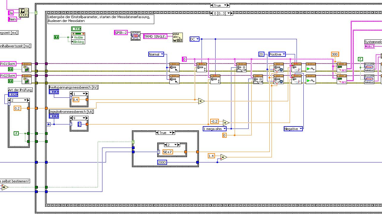
The first picture shows approximately where I started from (sorry I can't post VI, confidential...):
Only the middle part is interesting. Two sessions are initialized and manipulated parallel, trigger too. This has led to delays in the signals and should now be fixed. This apart from the VI works fine.
Goal is to trigger only on one channel but both devices! If possible, the device will trigger must be chooseable.
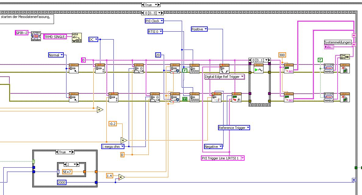
I started to rebuild the VI using the "EX Synchronization.vi 5xxx niScope' seeming spontaneity. The result is shown in the following image:
I tried different RTSI lines, but had no positive results. only the main channel has triggered.
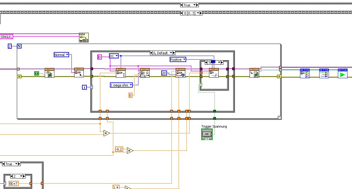
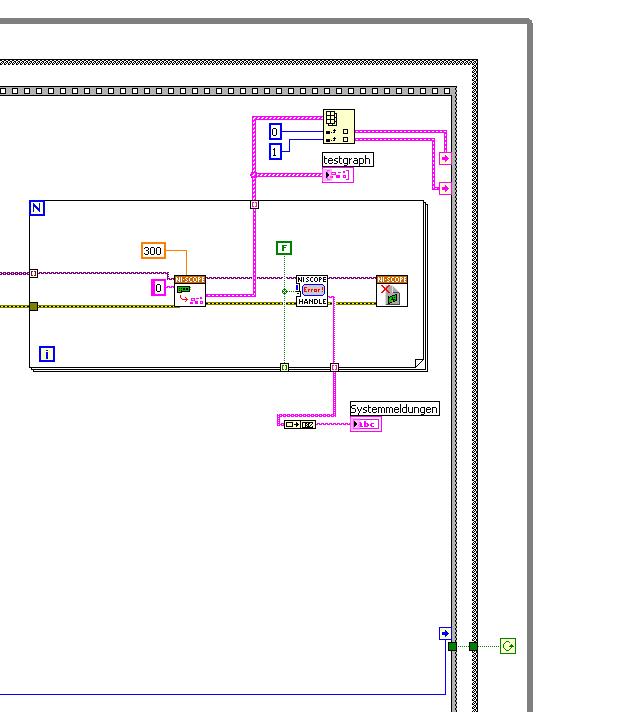
After this first approach, I looked in the "niScope EX .vi multi-Device configured Acquisition (TClk)" and other examples of TClk which seem to work for similar problems. The VI of reconstruction can be seen in the following images:
(Sorry, I had to use two photos..)
In this case, I didn't have no choice for trigger lines, it would automatically set the VI TClk. I tried to trigger on both devices, though. This second approach seemed promising to me, but it was an error:
"niTClk Synchronize.vi:1".
Index (starting at zero) of the session: 1
The error reported by the pilot of the instrument:
No registered trigger could be found between the
devices on the route.If you have a PXI chassis, the chassis correctly identify in
MAX and make sure that it has been configured correctly. If you use PCI
devices, make sure they are connected with a RTSI cable and that the cable RTSI
is saved to the MAX. Otherwise, make sure that there is an available trigger line
the trigger bus shared between devices.Source device: PXI1Slot4
Target unit: PXI2Slot4
Status code:-89125niTClk Synchronize.vi:1
Index (starting at zero) of the session: 1
The error reported by the pilot of the instrument:
No registered trigger could be found between the
devices on the route.If you have a PXI chassis, the chassis correctly identify in
MAX and make sure that it has been configured correctly. If you use PCI
devices, make sure they are connected with a RTSI cable and that the cable RTSI
is saved to the MAX. Otherwise, make sure that there is an available trigger line
the trigger bus shared between devices.Source device: PXI1Slot4
Target unit: PXI2Slot4
"Status code:-89125"
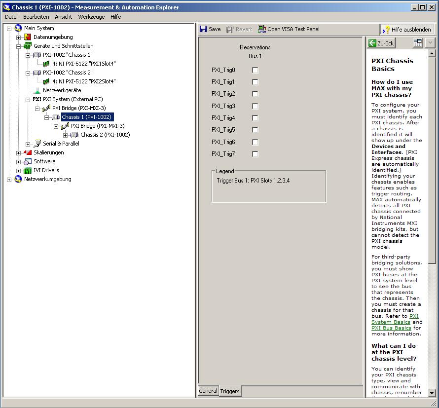
This error came back even after I've identified this drug as possible to the MAX, as shown in the screenshot:
In some of the textbooks, they showed how to get the MAX trigger lines, but as you can see, there is only booking options in my MAX. Whatever I do, I can't find options to define how to get my trigger signals...
In principle, it is possible to trigger instruments in different chassis, which is indicated in this Guide and others... the question that remains is can it be done with my set of components?
I understand that the use of multichassis compromised the integrity of the lines very adjusted as trigger in Star etc., so the configuration should be taken into account in some way, that my approach does not, I knew... But there must be a way to do this? And to start: to get just any signal from one device to the other trigger!
For any advice on this issue, I would be very thanfull!
Concerning
Max1744
Hi Max,.
Thanks for the detailed post and explanations of your application and requirements. You're right using TClk, because this is the optimal method to synchronize the 5122 digitizers. The original VI you worked with is unique for some of the legacy scanners and does not directly work with scanners based on the most recent CMS (for example the 5122). The good news is that you can synchronize these cards to separate chassis, but it will use the calendar 66xx and synchronization (T & S) cards in the chassis of the master and the slave, as indicated in the guide that you have accessed. These are needed because a common reference clock must be shared between them as well as a couple of tripping. MXI itself can not handle export triggers and clocks, so there is no way to do this without physically wiring between the chassis with cards T & S. Unfortunately, regardless of what specific method, you use for synchronization, it will take a material extra beyond what you currently have.
As one of your needs looks like it is necessary to retain wiring between the chassis directly, you may need to consider to synchronize using 1588 or GPS protocols. 1588 Protocol is a system for synchronization on the network while GPS course use antennas and locks for a common wireless signal. Although these synchronization methods may allow you to keep your chassis isolated, they will also require some manual configuration because you would be able to use the TClk synchronization and so the level of synchronization you can get between the cards may not be as good that can physically wire signals between the chassis using T & S cards.
Hope this helps,
-
I need to transfer a voltage using a PXI-5421 signal before a Council of PXI-2576 and then transfer it to an another Committee of the PXI-2576. For example I had set the signal of the ARB has then put 16 CH MUX 1(1st Switch), the value CH MUX 3 0 (switch 2) then read the MUX 3 voltage using a PXI-4071. I know that I can use the example of DMM Switch Handshaking.vi niSwitch for the rear. I'm just not sure how to transfer data to MUX 1, MUX 3?
Thank you
Denise Barajas
Hi Denise,
You must connect two switching modules to the outside. Signals may not actually be transferred through the PXI chassis backplane. Bottom of basket can only be used for communication by PCI bus and for the delivery of the trigger. You need to use external threads to physically send the signal of the first PXI-2576 to the second.
There are two ways to connect signals to the PXI-2576, you can use a block of endings that mounts to the front of the module PXI, or you can use a cable with a block of external connection. You can then connect the signal cables to the connectors to screws on the terminal/connector block. More information about the options of connection to the NI PXI-2576 connectivity products Page.
Hope this helps!
Chris G
-
Need to connect by Satellite U945-S4110 to the VGA-IN of the external monitor port
I need to configure my laptop Toshiba U945-S4110 to be connected to the VGA input of a display screen.
What do I need?Is this enough for this HDMI to VGA Converter active
http://www.Amazon.com/1080p-female-video-converter-adapter/DP/B008279OJ6/ref=sr_1_4?s=electronics&ie=UTF8&QID=1392112034&SR = 1-4 & keywords = hdmi + in + vga + adapter
then a VGA - VGA cable
> What do I need?
Well, the phone supports only the output HDMI port. This port sends the signal video and audio digital.
In the case where your external monitor supports only RGB (VGA) port, you will need to use some sort of adapter/converter, which would be able to convert the digital signal HDMI to VGA analog signal.
I put t know if the adapter might work, but you will not get sound because VGA does not support audio, only video signal.
-
Measurement error of the County of edge by using the external sample clock
Hello
I'm trying to measure the number of edges (rising) on a square wave at 5 kHz with a generator function on a device of the NI PCIe-6363. I configured a channel of County of front edge of counter at the entrance of the PFI8 device. I use an external sample clock that is provided by the output of the meter of a NI USB-6211 housing channel. If I acquire for 10secs then ideally I would expect to see a total of 50000 edges measured on the meter inlet channel. However, my reading is anywhere between 49900 and 50000.
When I use the internal clock of time base to measure the edges, the measure is accurate and almost always exactly 50000. I understand that when you use the external sample clock, the precision of the measurements is subject to noise level of the clock signal. However, I checked the clock signal is stable and not very noisy. Any reason why there is an error of measurement and how tolerance should I expect when using an external sample clock compared to when you use the internal time base clock?
Also, what is best clock Frequency (with respect to the frequency of the input signal) when using an external clock?
Thank you
Noblet
Hi all
Thanks for all your sugggestions. I was using an input signal with a function generator which had a range of 8V. It turns out that the reduction of the amplitude to 5V solves the problem. I was able to get accurate numbers with the 6211 external clock.
Thank you
Noblet
-
RelativeInitialX is valid for the externally triggered measures? NEITHER SMU 5122 64 MB per channel
For example when you use the following commands
niScope_ConfigureDigitial (with a positive delay)
NiScope_SetAttributeViInt32 (NISCOPE_ATTR_FETCH_RELATIVE_TO to NISCOPE_VAL_READ_POINTER)
followed by
niScope_FetchBinary16 (loop to retrieve the data most wfmInfo)
What will be the value of the wfmInfo.relativeInitialX before the external trigger? It matches? It is set to a number to indicate the outbreak did not appear until the trigger has been received and it then becomes accurate after receiving the trigger?
I would use it to make a set FecthForever to date, but synchronized to an external trigger waveforms up to about a minute.
It seems that the delay of release for the 5122 should be able to hande a minimum delay time of about 170 seconds (at the max rate of sampling more at lower rates), so the data I would need could all be borrowed buffers read-ahead externally triggered and properly after off-delay measurement.
Thanks in advance for any advice.
Greg
In the case that you are extracting data from before trigger (extraction of data before a relaxation was produced., relativeInitialX will have the same value as absoluteInitialX.)
Kind regards
Nathan
Maybe you are looking for
-
Everything that I try to use it requires java does not work on firefox. It just happened the other day, out of nowhere. It works on all other browsers I have except firefox. I can't even connect to my sync account because this action also requires ja
-
Problems with printing to a printer HP Laserjet 6 p to websites on the Beta 4. Any ideas?
When I print from a Web site, the information comes out blurred. Thoughts?
-
Re: Portege 500 Sync and Fingerprint Software on Vista
HI - have recently resolved the synchronization failure by removing the true Suite Access Manager (finger printing software). Vista invites you to reinstall the software when you restart, which I did download from the Toshiba... and we're back to the
-
need driver sd for pavilion hp low graded victory 8 to 64-bit 7pro
need driver sd for pavilion hp low graded victory 8 to 64-bit 7pro having been informed by HP suport, that there is no compatibility and none is available for a reader of sd card on my model # p7 - 1436 s that came with win 8 but was down ranked at p
-
I have 2 GB external usb external hard drive that appears in the XP and Win7 system tray, but not in my computer/workstation? When I go to the management of computer disk/storage/management - is not there in XP but it is for Win7. How to work various