Integrate the external trigger into camera (PCI-1424)
Hi all
I use a PCI 1424 acquisition card to take the image of a Kodak "camera".
Currently, I put the camera on a continuous mode - in which the camera give me frames one after one. I am able to 'snap' or 'capture' images of MAX with the help of the camera file. I can write a simple VI for 'break' a single image in LabVIEW.
Now, I want to go to the single camera viewing mode. In this mode, the unit will display a single image to a trigger signal (the rising edge of a singal TTL).
I wrote a short program for parallel port allows to send this signal triggered at the camera. The increase in power to the camera temporialy, I know that the camera captures an image.
However, the question is how can I nathalie caron this image?
What I do now, is to select 'snap' a picture to the MAX and allow a delay of 10 sec. After you click on the snap, I'll go to LabVIEW and send the trigger signal to the camera.
However, in MAX, I altenativley had a black and white image that is of the Court a false image.
does anyone know the reason?
and how do I integrate the VI trigger in the captuire VI image, so that I can finish the task of single capture inside a VI?
There is a sample VI "Grab.vi triggered" in which user can set waiting time and other properties for IMAQ1394, but I do not know how to PCI1424
Thank you very much.
Dear John,
I have attached this VI.
LabVIEW 7.1
Framegrabber: PCI 1424
Trigger the camera: after set us the camera in mode single shot (by rider material), I just need to send a signal of TTL and the camera will trigger in the front of this signal. So I schedule a pulse to the OID 0 pins at this TTL signal output.
Tags: NI Hardware
Similar Questions
-
Generation of digital signals through external trigger pulse on PCI 6251
Sir I want by NI 6251 because I read it has the ability to generate and acquire digital signals on port 0. I want to know that can I generate external clock wave triggering (providing impulses to a line on the acquisition of data)?
Hi Ali211,
Yes, you can use a source of sample for the digital input/output clock external clock. You can connect the external clock source to one of the lines PFI (PFI0-PFI15) and specify the source clock sample like this outer line of PFI.
There are some shipping DAQmx examples that you can start with. Find the examples by clicking Help > find examples in LabVIEW.
DAQmx continually reading digital channel with External Clock
DAQmx channel External digital writing Clock
Hope this helps.
Chris G
-
IMAQ Grab Acquire.vi error when you use an external trigger on a card NI PCIe-1433 (sync problem?)
According to my recent post on getting up and running with the NI PCIe-1433 camera link card, I ran into a bit of a snag.
When you use the internal trigger on the camera, everything works 100%. I can view all the data from the camera in MAX as well as in the labview project. However, whenever I have set the mode switch is where things start to fall apart.
What I have confirmed:
-Camera is switching between inside and outside triggering.
-NI PCIe-1433 camera link card is set up properly. While in external mode, I can trigger the camera by using a function generator and check the wire to the MAX. Everything works fine.
When the unit is in external mode, the function Acquire.vi enter IMAQ - my mistake VI. The error is:
Code :-1074397150
The possible reasons for a timeout.
Now, I have it set up so that a mistake here will not end the LabVIEW file. Sometimes, data of interest makes however (about every 10 seconds-ish). So what seems to be the case, it's that this external trigger signal is not in the lineup when the clamp is attempted. Is it possible to synchronize these? May reference the trigger signal external sort in my LabVIEW project so that the clamp is performed only when that trigger impulses?
So I solved my problem. He was in time. The external trigger that I used for the device was simply too slow. I was initially using a trigger from 2 Hz to be able to view the values changing on LabVIEW probes. But it was enough to get enough data to move above the camera cable to assemble a picture and kept it in time. Travel up to 9 kHz solved the problem. No adjustment to the camera settings or LabVIEW code was necessary.
-
Source of external trigger PCI-4472
Dear all,
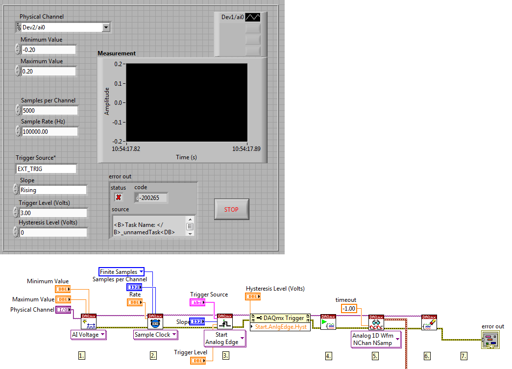
I have a PCI-4472 b I want to program to acquire a signal channel 0 whenever it recives a TTL signal throw the input external trigger.
I use a modified example but I don't know which is the name of the external trigger source. I always receive this type of error (for example if I connect to a string that contains "EXT_TRIG"):
Code: '-200265 '.
"DAQmx Start Task.vi:1 '.
Property: Start.AnlgEdge.Src
Value: EXT_TRIG" Task name: _unnamedTask
" The program I use is of this form:
First of all, this error means that I have no right external trigger source name entry?
If so, which one is the good name of the source of external trigger for NI4472B?
Thank you for the help
Hello
The error pops up because there is no channel named EXT TRIG. If you receive a trigger channel 0, I think that the best way is to specify the name of the channel in the "DAQmx Start Task. There is a terminal where you can specify the name of the channel and use that name to a string for the trigger input. I think this should solve the problem.
I referred to this knowledge base.
http://AE.natinst.com/public.nsf/webPreview/BEBB10D02D72798A8625736B0076B09A?OpenDocument
Also, looks like you have trigger 'start analog edge '. Since you want to get the TTL signal, why not try 'start digital dashboard' trigger?
Kind regards
-
initialization of the fgen on external trigger
Hello
For NI_Virtual bench with the BNC switch, we can trigger the function generator to start the square wave? I mean, I want to relax, so I have the beginning of the square wave
You cannot trigger the function generator to start in response to an external signal.
However, you can export a signal only pulses when the FGEN starts the external trigger BNC. You can do this with the entry point to 'Dig deeper the Signal to export'.
Kind regards
William Earle
OR R & D
-
Evanescent synchronization using the TTL trigger
Hi all
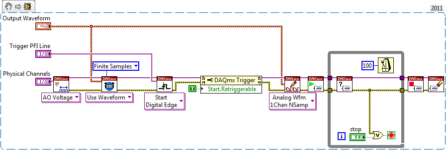
I work with the NI DAQ (PCIe 6363) set and uses a waveform as outputs analog to control a scanning unit.
Now I want this output to synchronize with the rising edge of an external TTL signal (the * fire * out of a camera).
To do this, I used [Cont Gen tension Wfm - Int Clk - analog Start] - model with minor changes (see attachment with a few comments included). In fact, it works, but only if the output signal is long finished when arrives the next TTL climbing aboard. What I want is a rising edge trigger that happens, say, 100 Hz, and a waveform near 10 ms-long that starts with this trigger. So far, I have to operate with a approx. 8 ms wavelength. It seems to me that the loop in Labview (see attachment) software takes the rest of the time. If I increase the wavelength to 9 ms or more, the loop is too slow and little miss the next rising edge trigger.
Unfortunately, I can't use [continuous sampling] that there is too much instability in the external trigger.
Is it possible to optimize this problem? For example, is it possible to tell la carte DAQ 'turn off this waveform whenever you receive the trigger"instead of"put on this waveform when you receive the trigger, then shut up? " Or is it possible to run two while loops in parallel that alternately hold the trigger signal and both use the same output channel? There is another, simpler solution?
Thanks for the pointers,
Peter
You must use the property start.retriggerable, something like this:
Best regards
-
Sync to external trigger in conjunction with a nearest pulse frequency device fixed...
I am writing an application running a scan frame. One axis of the scanner runs at a fixed frequency. I use a scanner high speed 5105 to get the data. The slow axis of the scanner is controlled by a servo with an analog input. I have will probably use an M-series card for analog control, but can also go with a 6713 (output only) or another Board. Fixed frequency Analyzer provides a clock line, I want to use to drive the 5105. In addition, the analog card must be synchronized in this. The entire system should be able to accept a trigger external devices, as it starts scanning at the edge of clock on next line.
I'm not quite sure about what would be the best way to do it. External triggering from other devices will be an indeterminate pulse width, so I can not just use it as a portal for the line clock. I am reluctant to do it in software (IE via the detection of changes on a digital line) because I want to be reliable started the next clock pulse. I have taken into account things like a counter/timer with a relaxing break, but which could lead to drift between the narcotics control and frequency scanner fixed. It seems just more complex that I think it should be, and it feels like I'm missing a simple way to do it.
Any suggestions?
Hi cshl,.
Good to know - the 5105 has a duty cycle of tolerance of 45-55% (mentioned on the page of the form), so that is why you cannot change clock speed from 3 to 12 MHz on-the-fly (though if you make small incremental updates over time, it would be theoretically possible).
With the additional information in mind, you might want to try the following on the 5105:
Use the external trigger as a trigger of departure (arm of acquisition).
Use the line as a signal reference clock (with a position of 0 samples for reference ~ 7500 are after initiation).
The problem with this is that you will have to re - trigger on each line - 5105 has a 2.4 rearm us time (also mentioned in the page on record). If this is unacceptable, another way that I can think of is to use a clock to external reference in PLL internal clocks of the bezel to. If you can provide a stable, a clock accuracy 50 ppm which is synchronized with your scanner within reach, would solve the problem of drift over time without having to re - trigger on each line (only acquire data continuously). This clock frequency must be between 1 MHz and 20 MHz in steps of 1 MHz.
We have no Council can take in an external variable clock up to 12 MHz (on-the-fly), but if you wanted to compromise a little bit the 6115 can enjoy up to 10 MHz, and has no obligation to cycle to 45-55% so it's maybe interesting look in.
As far as AO goes, I assumed that the clock line is declared after the quick scanner has completed his turnaround (ideally you do not update the zone of OCCUPATION during the lead time). If you have a signal Analyzer that you can use instead probably easier. If not, our peripheral series M and X series (but not the series AO 67xx) offer reference clock feature so if you go with the idea of reference mentioned above clock it may be easier to simply PLL the clocks together. These cards in a PXI chassis or are they PCI form factor?
I don't know what you mean by the sticking point about the need for two triggers. I think the idea is that we use the external trigger to arm the 5105 and clock line to trigger each record. However, if you do not need to generate a pulse double based on the clock of your line then you can use counters to do (our counters are redeclenchables with time to rearm in the ns range).
Best regards
John
-
RelativeInitialX is valid for the externally triggered measures? NEITHER SMU 5122 64 MB per channel
For example when you use the following commands
niScope_ConfigureDigitial (with a positive delay)
NiScope_SetAttributeViInt32 (NISCOPE_ATTR_FETCH_RELATIVE_TO to NISCOPE_VAL_READ_POINTER)
followed by
niScope_FetchBinary16 (loop to retrieve the data most wfmInfo)
What will be the value of the wfmInfo.relativeInitialX before the external trigger? It matches? It is set to a number to indicate the outbreak did not appear until the trigger has been received and it then becomes accurate after receiving the trigger?
I would use it to make a set FecthForever to date, but synchronized to an external trigger waveforms up to about a minute.
It seems that the delay of release for the 5122 should be able to hande a minimum delay time of about 170 seconds (at the max rate of sampling more at lower rates), so the data I would need could all be borrowed buffers read-ahead externally triggered and properly after off-delay measurement.
Thanks in advance for any advice.
Greg
In the case that you are extracting data from before trigger (extraction of data before a relaxation was produced., relativeInitialX will have the same value as absoluteInitialX.)
Kind regards
Nathan
-
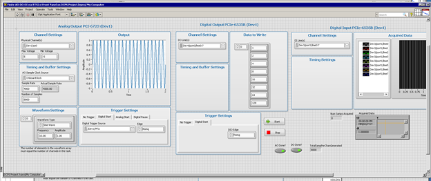
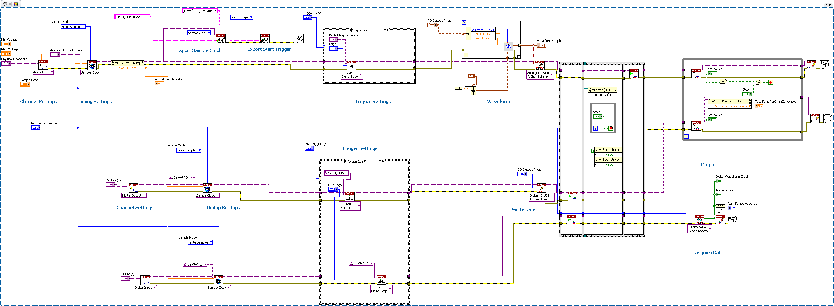
Several synchronization AO-DO-DI via DAQmx, external trigger devices
Having trouble getting the digital input to trigger analog output unit.
I have 2 AO cards (although I'm testing only with 1 device AO)
2 cards DIO - using one for output, one for input
All 4 cards are connected via a RTSI cable, and the cable is correctly condfigured in MAX, all 4 devices added to the cable.
I consider the AO the 'master' unit map In this test, I plead for a finite number of samples, and I'm outside triggering map AO.
As you can see, iI uses Signal export, export the AO and AO Start Trigger sample clock to DIO cards.
I'm using Labview 2012 on PC Windows 7.
The digital output is waiting for the AO trigger and appears off the coast of the AO sample clock synchronizing.
The digital input expires if I only fire at the time, so he does not expect relaxation.
any ideas? I tried all kinds of combinations.
Never mind! I solved the problem with digital input without waiting for the external trigger.
I just had to set the time-out waiting-1, so that he would never expire, and so he will wait for the trigger.
-
problems with several hr2000 + external trigger mode
I hope someone can me halp on this problem:
I need to acquire spectra with two hr2000 + and a nirques256 with labview external trigger mode.
The external trigger mode is done by another pc and also the train of pulpse generator.
If a trigger after I'm going to generate a 100 impulse every 20ms for each device through a dedicted Council.
If I only work with ghosts at times things works fine and the system is very stable, BUT if I work with two or three spectres by now I have a really strange (maybe for me) problem with the timeout.
This is due to an incorrect number of pulses:
If I work with two device then I need to produce pulses of 200 each 20ms but my spectrometers provide data every 40ms, but I need to equip every 20ms
If I work with threedevice and then I need to produce pulses of 300 each 20ms but my spectrometers to obtain data each 60ms but I need to equip every 20ms
Thus, in this way, I lose the synchronization of the three councils.
An options may be to use a dedicated pc for each device
I acquire the signal via usb and the problem is maybe duo to the bus
I think maybe the problem is duo to the vi block! Maybe I can use single istance at times when I call the procedure
Thank you
I just solved the problem: it was a problem with reentrancy
Default LabVIEW use not reentrant execution
-
AZ1VR Action Cam Mini with a Wi - Fi connection is the GPS integrated into the handpiece
I have the new AZ1VR Action Cam Mini with a Wi - Fi is the GPS integrated into the handpiece
cannellaj wrote:
I have the new AZ1VR Action Cam Mini with a Wi - Fi is the GPS integrated into the handpiece
Yes, get the GPS with the AZ1 to remote LVR2V wrist. You must also update the firmware in both devices. I have both and they work great.
-
5154 PXI trigger on the external input
I use a PXI-5154 and want to change my previous program to trigger the external source. I'm feeding the external source from source to V 2.5 and it seems to trigger fine. However when data acquisition the vertical range of the oscilloscope will 5 V which is too high as to my request I acquire in the millivolts range. I tried to show the vertical range of the channel I acquisition, but although I put it as the active channel I get the following error:
Error 1074118616 has occurred to the property node (arg 1) in PD_measurements_v11_test.vi
Get a base attribute value channel failed because the channels interviewed have different values. Please specify a channel when you query a string based attribute.
I enclose you a printsceen of the relevant part of the code.
Kind regards
Karavellas
Dear Tunde
I managed to make the changes you suggested and the works of the example. I'll look in my code and see what the problem is. I'll get back to you if it has been fixed in my code or not.
-
original title: read only the settings on my photos
I imported the photos from my camera to my computer and saved in a folder in my pictures. When I go into my photos and do turn and then try saving the picture, it says "you cannot rotate this image. The file may be used or open in another program or file or folder can be set to read only. "I have tried many and repeatedly edit the files and folders to uncheck Read-only, but it keeps changing its property back to read-only. I also know that the file is not open or in use anywhere on my computer. There must be something wrong with the parameters of only reading, but I have no idea how to do to figure it out, I tried several times to change.
Any help would be great!
Thank you!!
Okay, it looks like that your camera records the files in write protected files.
1. There should be settings on your cam to stop recording pictures like "non-indexed.
2. but right now, try this:Right click on image > click Properties > click on advanced > check / uncheck the ' Index
This file / folder...' option (should be the second option)
Click OK > click on apply.
and you'll see it disappear / appearYou can do this for all the photos (hold down the ctrl key while selecting to choose several files at once)
Eddie B. -
Load the XML file into Oracle external Table
I load the data from the XML file into an intermediate table Oracle using external Tables.Let's say below, it is my XML file
< header >
< A_CNT > 10 < / A_CNT >
< E_CNT > 10 < / E_CNT >
< AF_CNT > 10 < / AF_CNT >
< / header >
< student >
<>students-details
< Student_info >
< Single_Info >
< ID > 18 / < ID >
New York < City > < / City >
< country > United States < / country >
< Name_lst >
< Student_name >
Samuel < name > < / name >
Paul < Last_name > < / Last_name >
< DOB > 19871208 < / DOB >
Aware of < RecordStatus > < / RecordStatus >
< / Student_name >
< Student_name >
Samuel < name > < / name >
Paul < Last_name > < / Last_name >
< DOB > 19871208 < / DOB >< TerminationDt > 20050812 < / TerminationDt >
History of < RecordStatus > < / RecordStatus >
< / Student_name >
< / Name_lst >
< Personal_Info >
<>men < / Type >
< 27 > < / Age >
< / Personal_Info >
< / Single_Info >
< / Student_info >< student - register >
class < A >
< info >
< detail >
< ID student > 18 < / student >
EE < major > < / Major >
< course-Grades >
< course > VLSI < / course >
< degree > 3.0 < / Grade >
< / course-Grades >
< course-Grades >
< course > nanotechnology < / course >
< degree > 4.0 < / Grade >
< / course-Grades >
< / details >
< detail >
< ID student > 18 < / student >
THIS < major > < / Major >
< / details >
< / info >
class < A >
< Student_Enrol >
<>students-details
< student >I load this XML data file into a single table using an external Table. Could someone help me please with coding.
Thank you
Reva
Could you please help me how to insert my XML content into that.
Same as before, try a plain old INSERT:
insert into xml_pecos
values)
XmlType (bfilename ('XML_DIR', "test.xml"), nls_charset_id ('AL32UTF8'))
);
But you'll probably hit the same limitation as with the binary XMLType table.
In this case, you can use FTP to load the file as a resource in the XML DB repository.
If the XML schema has been registered with the hierarchy enabled then the file will be automatically inserted into the table.
Could you post the exact statement that you used to save the scheme?
In the meantime, you can also read this article, I did a few years ago, it covers the XML DB features that may be useful here, including details on how to load the file via FTP:
https://odieweblog.WordPress.com/2011/11/23/Oracle-XML-DB-a-practical-example/
And documentation of the course: http://docs.oracle.com/cd/E11882_01/appdev.112/e23094/xdb06stt.htm#ADXDB4672
-
I used to download pictures from a card reader, copy them, and then stick it on my external hard drive. Since El Capitan of download, it does not work - I can download and copy, but can not stick to the external hard drive. I can't set up the files on the external hard drive either. However, I can download what is already on the external hard drive without any problem.
How the external drive is formatted?
Maybe you are looking for
-
I can't do the nets of the messages to show everyone.
I read the article describing the threads of the emails but cannot get anything it either appears. Only the original message is indicated.
-
You can see movie dvd on windows 8.1
I have a laptop with windows 8.1 want and wanted to see a movie about it. I can't find a software that allows me to watch a movie. The laptop came with a DVD player, but I buy a DVD player. I can burn DVDs, but I can't seem to figure out how I can wa
-
I buy the software of our University webstor and download all the files of it. When I try to install the labview 2012 in my 64-bit Windows 7 systems: (1) when I click on autonrun.exe and it shows not install, but I click intall, there is no answer; (
-
CP6015: 6015 jams after it gets hot
He jams after it gets hot. I let it sit and it'll print maps of 50 or more. I can't find anything to support title. Is there something to fix or clean?
-
Windows will not be updated 360 controller driver
I had an old map gigabyte mother and recently upgraded to an asus Z170m-E d3 motherboard and everything working again except my 360 controller began. the pilot will be not updated for some reason, Ive tried to change the USB port, uninstall and re in