6229 USB meter
HI, I connect acquisition of data USB 6229 quadrature encoder, I connect CH A PFI 0/P1.0 or PIN 73 and PFI 0/p1.1 or PIN 74 and I'm setting them up as a counter or a desk reading in. The USB6229 of data acquisition is not read these signals as a counter. How I would read the counts of a quadrature encoder, using materials DAQ 6229.
Regads;
JH
The fact that it is the reading of thousands and millions usually means that there is noise on the signal that is picked up as the account when it really shouldn't be. To correct this, you must activate digital filtering:
See the example:
Use the digital meter Debounce filter
and page 7-32 to 7-33 of the M series user manual for details of what a digital filter is and the different settings available for the 6229.
Activation of the filter will get rid of the very high frequency on the digital line noise and must get rid of the extremely high values and instead to give a good account of 256 / rev.
Tags: NI Hardware
Similar Questions
-
USB cable for Bayer will not work.
I have connected to the computer and use the software cd that came with it and nothing worked
What software Bayer are you talking about? See your documentation for system requirements and software compatibility. some of their software is not compatible with win 7.
See also bayer support Web site.EDIT: If you mean contour usb meter bayer: -
How to start collecting data through digital triggering entry user GOLD
Hello
I have a vi with which I would like to collect data. It is configured to start to perceive when the start trigger is detected, which works perfectly, but I would also create a user can start the process of data collection by pressing a button instead of apply the trigger. I am at a loss on how to do it. I thought that the structure of the event would work well; However, the relaxation has no Boolean value I can associate it with. If that were the case, I could then perform a logical comparison between the trigger and the button to determine if the collection of data should begin.
So, how can I represent a trigger activated as a Boolean value? Or is there a better way to reach my goal?
I think I can make things clearer by expressing in linear programming that it is, I'm trying to achieve:
If (trigger == true: button == true) {}
begin to collect data
}
I have attached my vi where someone feels useful.
Hello
You're right, 6229 USB is certainly not compatible with NO-Sync. However, you should be able to do with the DAQmx driver functions.
If I understand correctly, you want to generate a graph of your analog input and have this file based on a triggered event entry. A line using PFI will not work for this particular function, but you can create a task digital input instead and pass the thread to a D e/s instead of a PFI line line. You can then use for/no-write the analog input file using a case structure depending on the State of the digital line.
I hope this helps! Let me know if you have any other questions.
-
Double counters in Signal Express with a USB-6229
I have a USB-6229, which I'm running via SignalExpress, and I am trying to simultaneously record two inputs of meter. However, it seems that he has trouble to add the second channel. When I add the first string via signals acquire > DAQmx Acquire > counter entry > Position > angular and select ctr0 channel, he (correctly) lists PFI8 and PFI10 as inputs of channels A and B. However, when I add the ctr1 channel to the same task (via the blue and the button "Add a channel"), he still lists the same PFI8 and PFI10 as input.
On the other hand, if I first add ctr1 then add ctr0 Secondly, it lists PFI3 and PFI11 as A and channel B for the two entries of meter.
How can I get the two counters operating independently?
Thank you
Josh
He realized that I can't run two meters of a single task in Signal Express (unlike, say, two analog inputs). Once I added it as two separate tasks, everything works fine.
Now I have problems of synchronization. Looking through these tips and documentation, it seems that I will not be able to fix this via SignalExpress, so I continue in LabView. I'm having some problems with it, but I'll post in a new thread here.
-
How long can I count edges on a USB-6229?
I have a USB-6229, and I want to count the edges using one of the built-in meters. My question is what is the maximum frequency that the meter can the edges of the County of my signal? (I will not mention what my signal frequency because I want to know how to determine the maximum value...)

Hello
Napo2 really seems to ask questions on the highest frequency that can be introduced to the counter to an external source. The best spec for this is the counter 'external clock frequency Base', found in the specifications of 622 x, which claims 20 MHz. The factor limiting here really is the bandwidth of the digital front end on the PFI lines. Internally, the meter is able to count the time base of 80 MHz directly, but a signal to this rate would be completely mitigated by the digital front end of the card if you tried to pass from an external source. The 20 MHz depends on having a square clean wave to come in the card, even if it is not very precise about the time of ascent or minimum pulse widths. You might be able to go a bit beyond 20 MHz, if you have a very clean signal (and conversely, might not be able to hit 20 MHz if signal is not a clean square wave).
This KB previously bound doesn't seem to not relate to the original question of Napo2, and it is also somewhat misleading in general:
The measurement of the period is determined by the frequency source that can be acquired. For Counter/Timer boards, the highest frequency, we can accurately measure will depend on the time base higher frequency for the individual Council.
It's true, in the sense that the higher frequency time base is a factor that plays in the precision of a measurement of the period. However, the KB seems to imply that the maximum that can be measured is the inverse of the maximum time base and does not give further guidance for the determination of the accuracy of the measurement period. A better reference (if you were interested in these things) would be the table in the Manual X series, but even once, this is not really related to the original question.
Best regards
-
Properties of the scanclock exported by Matlabs addClockConnection() on a 6229 OR USB (BNC)
With the Matlab DAQ Toolbox, it is possible to export a scanclock by addClockConnection() (see http://www.mathworks.de/de/help/daq/ref/daq.session.addclockconnection.html for an example of code base).
However, I found no information on properties signal exported on the NI USB 6229 (BNC), for instance frequency, amplitude, duty cycle, etc., or in the documentation, or on the web or in this forum.
I would be very happy if someone can point me to the documentation for the properties of scanclock.
Hello
All channels in a MATLAB session running at the same pace. So, if you create a session', s.Rate would be the rate of your acquisition or production. the 's.addClockConnection' method allows you to import or export a clock to analysis for synchronization purposes. The syntax below allows you to export the session of 'PFI0' on an external device clock. You can probably find documentation on the Web site, OR to the properties of the embedded clock signal, but it seems to be a pulse of 5 volts running to the session rate - which is typical to synchronize the devices together.
s.addClockConnection ('dev2\pfi0', 'external', 'ScanClock');
If you need duty cycle 50%, you must create your own clock using a channel of meter output as you did above. If you connect the clock to the GET, it can use it; and if you need your equipment OR to dribble the clock output of counter (instead of the clock on board), you would also import counter signal output in the session and be sure to set the rate of session to match the output frequency of the counter. Assuming that s.Channels (2) is your output channel of the meter, the code below imports terminal scan on the same clock as the meter output channel, so no extra wiring is necessary.
s.Rate = s.Channels (2). Frequency;
s.addClockConnection ('external', ['dev2\' s.Channels (2).]) (Terminal Server], "ScanClock");
This allows the device OR both your GET to run on the same clock. You can also have your session export a trigger to start with the syntax simillar to the above to make sure two devices on the same edge of clock.
s.addTriggerConnection ('dev2\pfi0', 'external', 'StartTrigger');
I hope this helps.
Kind regards
whemdan
The MathWorks
-
Temperature measurement and the CJC using thermocouples on a USB - 6229 BNC
Hello
I'm trying to get the measurements of temperature using type K thermocouples on the box nor usb-6229 BNC. SignalExpress software doesn't let me choose 'Built In' to the Source of the CJC. So, I must select 'Constant', which means that I then have to follow the evolution of the temperature during the day with a separate meter and adjust the value of CJC accordingly to maintain an accurate reading. Is there a way around that to avoid having to monitor the room temperature at the junction?
Thanks in advance
Mike
Hi Mike,.
It seems that you have managed to find a solution for you have this problem, which is great news.
However, for future use, if you had bought the 6229 with massive ending (rather than the interface BNC) then you might have interfaced unit with a block of connection SCB-68 (see link)
http://sine.NI.com/NIPs/CDs/view/p/lang/en/NID/1180
The SCB-68 has a CYC source built-in, so you might have used in conjunction with 6229 (mass layoffs).
A bit of in the way, but I thought you may be interested.
Best wishes to you all
-
How to connect USB 6259 so that I can generate trains of pulses of a meter
Hello
We just bought NI USB-6259 BNC. We used to use BNC-2110, which integrates the connectors BNC for trigger and the meter so that we can send trains of pulses through it to our electric Stimulator.
However, I find no terminal BNC for the output of the meter on the new device. Could someone teach me how do?
Thank you
Jay
Hi, Jay.
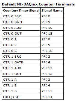
Big question. The screenshot below will give you the Signal of Counter/Timer associated with its respective PFI line:
This table is located in the NOR-DAQmx help (using terminals of NOR-DAQmx devices"OR USB - 6259 BNC).
To access these lines PFI one of the BNC (User 1 and User 2) user-defined, the line due to PFI line of the user desired. For example, if I wanted to access counter 0 Out of 1 BNC user, I would wire pin 1 USER on pin 12 of PFI. Manual specifications USB-6259 BNC does not give a good description of how to access the user 1 and user 2 BNC, so I refer to page 9 of the Manual of the BNC-2110. It's the same idea, just different pinout.
Let me know if you need more information. I hope that you are having an amazing day!
-
synchronize two usb 6289 with a meter
Hi people!
I'm trying to synchronize 2 boards of the series M USB-6289 using a counter.
I searched the forum and that you've already seen the tutorials:
'Synchronization of series M with LabVIEW and NOR-DAQmx - Developer Zone - National Instruments'
'Synchronization of data acquisition USB - device to several systems - Developer Zone - National Instruments'
"The time and the synchronization of the NOR-DAQmx - Developer Zone - National Instruments features."
However, I still have some doubts (where the post
 with respect to the following:)
-If I want to use the meter as trigger for both cards do I need to export to a PFI line and connect to the Member of the Board?
-I do the same thing with the clock signal (export to the other panel using a PFI line) or using the same frequency for two meters is enough? Or both?
-can I use the same value for the frequency in the meter and two clocks?
Hope someone can help out me.
If possible, underline some examples or detachment would be great.
Thanks in advance for the help!
See you soon!
Hello
All points depend on what you need to synchronize exactly.
As you have probably already read in the links you provided, you have the option to share a trigger, or a clock, or both.
Of course, the best solution is to share together.
Then, you can choose to directly share the sample of one blade to the other clock (if the two sampling rates are the same), or to move the reference clock, then, both cards will synchronize their sample (with PLL) clock on the same reference clock, as shown in the synchronization M with LabVIEW and NOR-DAQmx series.
Exactly how you want to use your meter?
You want to generate a single trigger pulse?
Then, for examples of synchronization, there are some zip files at the end of the links that you have read.
Kind regards
-
Hello
I have a power meter which provide the USB driver and a Labview program to get the data and NI USB-6221. The project I am currently working on the needs of:
1 acquire two signals (inputs of simple tension), pressure frequency KHz
2. acquire a flow signal, the output signal is 0 to 5V pulse, each pulse means 0.4 ml volume. So I use a voltage inflows to count impulses in certain period of time (in this case, 1 S) for water flow. ; KHz sampling frequency and the 1 Hz update rate
3. acquire a signal of engine speed. The output signal is pulse square wave whose frequency is related to the speed. I use a REIT port to measure the frequency. Sampling rate: Auto
4 give output voltage sine or square wave, I use AO do that.output rate: Auto
5 acquiring by VISA electricity meter data. Data update rate: every 50ms
Currently, all the 5 tasks work well separately. But when I put them together, some signals are beginning to hang, for example, pressure signals sometimes give nothing.
Another problem is the data record. I programmed the VI in such a way that whenever I press the button 'save start', he begins to record data and save them in a .cvs file. For some reason, I always get only the data in the first table. Coult someone help me? I download my code as follows
Hello
What I meant by open, write, close. For any type of file you are using.
Open the file, which produces a reference, then put the mention in a registry to offset.
Write data, using the function write (for this type of file) and the reference.
When you are finished, close the file reference.
Writing in the spreadsheet opens, written, close all at once. It is very good for this type of application.
***
The issue of the loop is more general. I would like to say first of all, I want to say that since each loop works on its own, it is own VI, and that this program has put all this into a single VI, which has a method to solve the problem is to disable all the loops and allow them one at a time to see if there is a culprit responsible for.
Using multiple loops executes the code at the same time, and some loops would be cycle faster than others, especially if some of them are loops just as they are.
Communication between the loops is a test to the address if necessary.
Running all these signals through different loops DAQ must also be examined. Don't know what questions are for read and write somewhat randomly in the channels.
-
USB-6229 is to give significant fluctuations in the measured values when no signal is applied.
To study the problem, I plugged a resistance of 100R between AI0 and AI8 (differential voltage mode)... problem persisted.
Measured 5V (PIN 96)... varies between 2.0V and 4.0V... with sporadic noise.
Input power was measured at constant temperature of 12 v to the input fuse.
Is there anything I can do for this...
Panorama,
You can visit the page warranty and repair for the replacement of related issues
Kind regards
Danny F
-
Interrupted the enclosure or usb-6229 during recording and performance data is now not viewable
Hello
I've been recording in Labview SignalExpress 2.5 using the usb-6229 BNC recorder. I was recording on 16 channels with a sampling frequency of 1 kHz over a period of at least 7 hours, while you can imagine a lot of data has been collected. Unfortunately, the power of the recorder was interrupted during recording (but not the PC running Signal Express) and although all the tdms files are present, they will not playback. When I drag the log on in the display area of data, I get the following error message:
' The selected journal is ready for posting. You must wait until the log has finished recording to view it".
If I right click on the journal before sliding above, I get a list of options that is "making visible journal." If I select this, nothing happens at all. If I then right click again, the 'Make visible log' option disappeared. Drag the log on after this step still does not work.
I recorded other newspapers of more than 7 hours that read perfectly well.
If the log files be constantly updated during recording, so that if there is a failure of Rubio, the data are not lost?
The most important thing first, but that is something so that I can play these logs back or are they gone for good? The .tdms file size match those of other file formats that play OK and have the same duration 7hr for registration.
Thanks in advance
Mike
-
PWM - output meter (PFI4) USB-6211
I managed to control a motor based on PWM signal output via USB-6211 AO continuous. Now, I'm trying to use the Terminal counter instead.
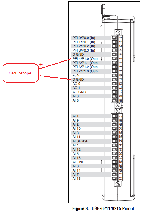
Can't seem to make it work. NA not get a signal when link the PFI4 terminal to an oscilloscope.
I don't know wheather my coding is wrong or does not have my wiring (i.e. of USB-6211 for motor continuous). I need to use the terminal of meter that I used the analog output to a different measure.
Please advice. Attached encodings.
Thank you very much.
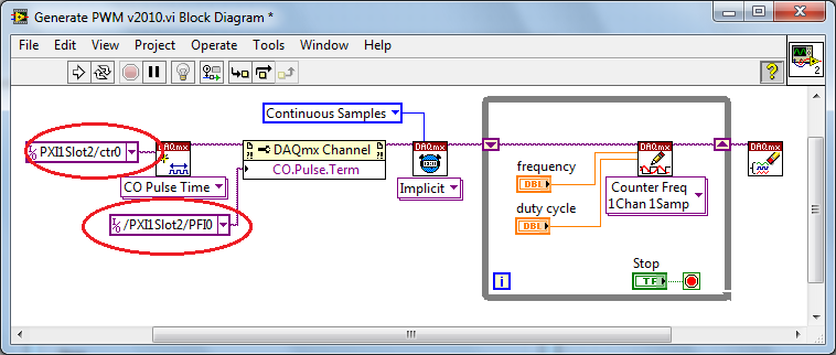
Front of conneting to DC motor, make sure first that the PWM is get generated correctly... use oscilloscope.
And have you changed the constant (physical terminals) for your device...?
Change to:
Dev1/ctr0 & Dev1/PFI4 and the scheme of connection must be:
-
Synchronization of a PCI-5114 with a USB-6229
Hello
I'm doing several measures with a couple of scanners OR: the first is a PCI-5114 who reads a signal using the maximum sampling frequency of the 5114. It works currently, and is triggered by a digital pulse at 1 Hz.
Secondly, I have 5 other channels, and I want to measure the maximum voltage on each (analog inputs), at the time the PCI-5114 saves the data. My thought was that I could have the USB-6229 reading data continuously, then 5114 triggers, once I read the files ~ 1000 previous of the 6229. I'm not sure it will work, because I can't be sure that the data the 6229 collects will be the same time as the data that the 5114 collects. Is there a smart way to ensure that is the case? (external clocks, exported triggers the 5114... I do not know what are the options)
For full disclosure, I have 8 digital outputs through the same USB-6229.
Furthermore, if there is a good way to measure the max of each of my 5 channels without having to download 1000's of data points, which would also work.
Any help or advice is much appreciated! Thank you!
Karl
Hi Karl,
The reference of 6229 media triggering (manual link), if you could start it off the same signal of 1 Hz you use to trigger your scope. You can specify the sampling frequency, number of samples and number of samples to relax pre - this should allow you to correlate your acquisition on the map of data acquisition to the time window even that your scope is acquiring data. The clocks would still be independent, but I don't think it matters too much because you are triggering the same external signal every second.
After that the DAQ trigger card you will need to re - start the task in software to re - arm (something like in This example), but the interval of 1 Hz should be more than enough to do this.
Best regards
-
OR USB-6229 unused outputs floating
Hello!
I have a DAQ NI USB-6229 map and I want to generate a current (I use shunt resistors) and inject it into a resistor network. While doing this I also want to measure 6 potential to a few nodes on the network. This procedure is then repeated four times, and for each new set of measures, I want to change the current node injection.
I managed to make a flat sequence version that works sort of "semi-automatic", that is. I manually move the connector for the injection of current corn,
now I would like to program to do this for me. The problem I face then is that I have to connect to all channels of analog output to my network and I can't make it floating. So I need to get the voltage on shunt temporarily "unused" zero resistance and make them floating. I was thinking of doing a while loop which regulates the voltage, but then how to leave the loop everything with it regulate the voltage?
Is there maybe a solution to this problem?
Thanks in advance!
/
EmanuelIt is much clearer. Thank you.
If all of your applied voltages, including tensions applied to generate the currents I1 and I2, are positive, you can then use diodes to rpovide isolation. You are already set up to measure the tension, it should be possible to offset decreases of voltage diode.
Another approach would be to exploit the tensions in potentiometric mode to make zero currents. Let me define some terms using your diagram: V1 = voltage applied to create the current I1. V1n = input to the network in the I1 circuit voltage when I1 current circulates. Of the law of Ohm I1 = (V1 - V1n) / Rshunt. Similarly V2 and V2n refer to tensions related to the current I2. To define the I2 = 0, V2 = V2n. Of course the tension to V2n will depend on the voltage and current elsewhere in the network.
To join the operation points you want will require an iterative process. Consider the case where I1 = 1 and all other currents are zero. The procedure might look like this:
1. apply the V1. Set all tensions to zero.
2. measure the V1, V2, V1n, V2n...
3. calculate all currents.
4 calculate all voltages to change the values you want, using the assumption that tensions n V [i] do not change.
5 connect the calculated in step 4.
6 repeat step 2 until the new tensions calculated in step 4 are close enough to the values of the previous iteration.
If the network is linear, but the values are not too extreme, it will probably work. If it is not the case, you may need to scan the network to see if its admittance matrix is singular, or the range of values is too broad.
A state machine would be a good program architecture to implement an algorithm like that.
Lynn
Maybe you are looking for
-
OSX Preview app 10.11.6 prints blank pages.
Preview app will not print any pdf open. Screen print preview is blank. By using the menu at the bottom left to save the pdf in one other app sends a blank document Reinstalled OSX - no change. New Macbook Pro (early 2015).
-
After surfing the help article titled 'profiles - where Firefox stores your bookmarks, passwords and other user data', I still couldn't locate my profile. My old computer was down and I was able to read the data from the old hard drive, it was in Win
-
Hi all Just looking for help with my new laptop e009ax. I'm unable to update Windows 8.1 even after the help of online support. Looking for other forums, it seems that there is a problem with the bluetooth driver / Ralink RT3290 wireless. I can do
-
XControl - behavior strange element parameters
Hello I develop an XControl and I came across a strange problem. If I create a property and go in properties XControl-> settings for and select property, I am able to set the Unique identifier, description, etc. But when I close the project and open
-
My hotmail account has been hacked, as was my facebook that I luckily managed to connect to another email. However, the hacker has changed my password on my hotmail and my scurity question has also been changed. The mobile phone number, I recorded wi