OR USB-6229 unused outputs floating
Hello!
I have a DAQ NI USB-6229 map and I want to generate a current (I use shunt resistors) and inject it into a resistor network. While doing this I also want to measure 6 potential to a few nodes on the network. This procedure is then repeated four times, and for each new set of measures, I want to change the current node injection.
I managed to make a flat sequence version that works sort of "semi-automatic", that is. I manually move the connector for the injection of current corn,
now I would like to program to do this for me. The problem I face then is that I have to connect to all channels of analog output to my network and I can't make it floating. So I need to get the voltage on shunt temporarily "unused" zero resistance and make them floating. I was thinking of doing a while loop which regulates the voltage, but then how to leave the loop everything with it regulate the voltage?
Is there maybe a solution to this problem?
Thanks in advance!
/
Emanuel
It is much clearer. Thank you.
If all of your applied voltages, including tensions applied to generate the currents I1 and I2, are positive, you can then use diodes to rpovide isolation. You are already set up to measure the tension, it should be possible to offset decreases of voltage diode.
Another approach would be to exploit the tensions in potentiometric mode to make zero currents. Let me define some terms using your diagram: V1 = voltage applied to create the current I1. V1n = input to the network in the I1 circuit voltage when I1 current circulates. Of the law of Ohm I1 = (V1 - V1n) / Rshunt. Similarly V2 and V2n refer to tensions related to the current I2. To define the I2 = 0, V2 = V2n. Of course the tension to V2n will depend on the voltage and current elsewhere in the network.
To join the operation points you want will require an iterative process. Consider the case where I1 = 1 and all other currents are zero. The procedure might look like this:
1. apply the V1. Set all tensions to zero.
2. measure the V1, V2, V1n, V2n...
3. calculate all currents.
4 calculate all voltages to change the values you want, using the assumption that tensions n V [i] do not change.
5 connect the calculated in step 4.
6 repeat step 2 until the new tensions calculated in step 4 are close enough to the values of the previous iteration.
If the network is linear, but the values are not too extreme, it will probably work. If it is not the case, you may need to scan the network to see if its admittance matrix is singular, or the range of values is too broad.
A state machine would be a good program architecture to implement an algorithm like that.
Lynn
Tags: NI Hardware
Similar Questions
-
Synchronization of a PCI-5114 with a USB-6229
Hello
I'm doing several measures with a couple of scanners OR: the first is a PCI-5114 who reads a signal using the maximum sampling frequency of the 5114. It works currently, and is triggered by a digital pulse at 1 Hz.
Secondly, I have 5 other channels, and I want to measure the maximum voltage on each (analog inputs), at the time the PCI-5114 saves the data. My thought was that I could have the USB-6229 reading data continuously, then 5114 triggers, once I read the files ~ 1000 previous of the 6229. I'm not sure it will work, because I can't be sure that the data the 6229 collects will be the same time as the data that the 5114 collects. Is there a smart way to ensure that is the case? (external clocks, exported triggers the 5114... I do not know what are the options)
For full disclosure, I have 8 digital outputs through the same USB-6229.
Furthermore, if there is a good way to measure the max of each of my 5 channels without having to download 1000's of data points, which would also work.
Any help or advice is much appreciated! Thank you!
Karl
Hi Karl,
The reference of 6229 media triggering (manual link), if you could start it off the same signal of 1 Hz you use to trigger your scope. You can specify the sampling frequency, number of samples and number of samples to relax pre - this should allow you to correlate your acquisition on the map of data acquisition to the time window even that your scope is acquiring data. The clocks would still be independent, but I don't think it matters too much because you are triggering the same external signal every second.
After that the DAQ trigger card you will need to re - start the task in software to re - arm (something like in This example), but the interval of 1 Hz should be more than enough to do this.
Best regards
-
With the help of several outings on NI USB-6229
Hello
I have a question about the use of several output (input) on NI USB-6229. I request of programming where I use a few digital, digital inputs, outputs some analog outputs and inputs. Initialization of all the ports that I have in a Subvi, which lies in a loop for I control settings on the other for loop by using notifications. Problem is that this outpust is really slow (or reading entries), I want to say in my main loop I setting button, but it takes at least 1 s to change my outings (even with reading entries)? So I am wonderig what I am doing wrong. Can plesae you tell me what is the best way how to control several different ports?
OK, so my whole program structure is like this:
In primary Vi, I have a loop that subvis in other control loops. One of the Subvi is Subvi whichchange parameters at initialization Subvi. The structure on the photo. Please help me because I really don't know where is the problem. I use two converters AD / DA more and some machines that I am targeted by using the RS232 but it NEITHER original is the slowest.
PS. If I turn on only parameter Subvi loop everythinf is much faster.
OK problem with loops slow fixed http://forums.ni.com/t5/LabVIEW/Slow-parallell-loops-with-DAQ/m-p/1698988#M601731.
-
Double counters in Signal Express with a USB-6229
I have a USB-6229, which I'm running via SignalExpress, and I am trying to simultaneously record two inputs of meter. However, it seems that he has trouble to add the second channel. When I add the first string via signals acquire > DAQmx Acquire > counter entry > Position > angular and select ctr0 channel, he (correctly) lists PFI8 and PFI10 as inputs of channels A and B. However, when I add the ctr1 channel to the same task (via the blue and the button "Add a channel"), he still lists the same PFI8 and PFI10 as input.
On the other hand, if I first add ctr1 then add ctr0 Secondly, it lists PFI3 and PFI11 as A and channel B for the two entries of meter.
How can I get the two counters operating independently?
Thank you
Josh
He realized that I can't run two meters of a single task in Signal Express (unlike, say, two analog inputs). Once I added it as two separate tasks, everything works fine.
Now I have problems of synchronization. Looking through these tips and documentation, it seems that I will not be able to fix this via SignalExpress, so I continue in LabView. I'm having some problems with it, but I'll post in a new thread here.
-
USB-6229 is to give significant fluctuations in the measured values when no signal is applied.
To study the problem, I plugged a resistance of 100R between AI0 and AI8 (differential voltage mode)... problem persisted.
Measured 5V (PIN 96)... varies between 2.0V and 4.0V... with sporadic noise.
Input power was measured at constant temperature of 12 v to the input fuse.
Is there anything I can do for this...
Panorama,
You can visit the page warranty and repair for the replacement of related issues
Kind regards
Danny F
-
Interrupted the enclosure or usb-6229 during recording and performance data is now not viewable
Hello
I've been recording in Labview SignalExpress 2.5 using the usb-6229 BNC recorder. I was recording on 16 channels with a sampling frequency of 1 kHz over a period of at least 7 hours, while you can imagine a lot of data has been collected. Unfortunately, the power of the recorder was interrupted during recording (but not the PC running Signal Express) and although all the tdms files are present, they will not playback. When I drag the log on in the display area of data, I get the following error message:
' The selected journal is ready for posting. You must wait until the log has finished recording to view it".
If I right click on the journal before sliding above, I get a list of options that is "making visible journal." If I select this, nothing happens at all. If I then right click again, the 'Make visible log' option disappeared. Drag the log on after this step still does not work.
I recorded other newspapers of more than 7 hours that read perfectly well.
If the log files be constantly updated during recording, so that if there is a failure of Rubio, the data are not lost?
The most important thing first, but that is something so that I can play these logs back or are they gone for good? The .tdms file size match those of other file formats that play OK and have the same duration 7hr for registration.
Thanks in advance
Mike
-
How long can I count edges on a USB-6229?
I have a USB-6229, and I want to count the edges using one of the built-in meters. My question is what is the maximum frequency that the meter can the edges of the County of my signal? (I will not mention what my signal frequency because I want to know how to determine the maximum value...)

Hello
Napo2 really seems to ask questions on the highest frequency that can be introduced to the counter to an external source. The best spec for this is the counter 'external clock frequency Base', found in the specifications of 622 x, which claims 20 MHz. The factor limiting here really is the bandwidth of the digital front end on the PFI lines. Internally, the meter is able to count the time base of 80 MHz directly, but a signal to this rate would be completely mitigated by the digital front end of the card if you tried to pass from an external source. The 20 MHz depends on having a square clean wave to come in the card, even if it is not very precise about the time of ascent or minimum pulse widths. You might be able to go a bit beyond 20 MHz, if you have a very clean signal (and conversely, might not be able to hit 20 MHz if signal is not a clean square wave).
This KB previously bound doesn't seem to not relate to the original question of Napo2, and it is also somewhat misleading in general:
The measurement of the period is determined by the frequency source that can be acquired. For Counter/Timer boards, the highest frequency, we can accurately measure will depend on the time base higher frequency for the individual Council.
It's true, in the sense that the higher frequency time base is a factor that plays in the precision of a measurement of the period. However, the KB seems to imply that the maximum that can be measured is the inverse of the maximum time base and does not give further guidance for the determination of the accuracy of the measurement period. A better reference (if you were interested in these things) would be the table in the Manual X series, but even once, this is not really related to the original question.
Best regards
-
I am trying to build a VI to control a single relay to open and close 5 valves in series pour.5 seconds. I have a USB-6229 Control Board to do so. I am new to labview and need help the code for the VI. Any suggestions would be helpful.
Try this...
-
Linux drivers for the acquisition of data USB-6229
I would use a USB-6229 with Linux and support driver selection guide said that this model is not supported. However, the 6218 and others are supported. Is it possible to use 3. 5B pilot defined for a USB-6229 with reduced functionality? Is it possible, with some basic Linux knowledge codification driver of change 3. 5 b drivers to work with a USB-6229?
Kind regards
Craig
Hi Craig,.
That is right.
Best,
-
It is current on the analog module USB NI 9263 output voltage limit (+/-10 v)?
It is current on the analog module USB NI 9263 output voltage limit (+/-10 v)? I try to run a current controlled resistance, but cannot get the required current. The servovalved has a parallel internal resistance of 80 ohms and requires 20 my full operation. Ohm's law: (.02 A) * ((80*80) /(80+80) ohms = 4.5 v) Yet, the required voltage, do not move the servo. Outside the material error (continue this by other means), what could be the problem?
Have you checked the Manual?
Page 12 1 says my.
For servo, you really need some kind of amplifier. See if the manufacturer provides the electronic driver for it.
-
Temperature measurement and the CJC using thermocouples on a USB - 6229 BNC
Hello
I'm trying to get the measurements of temperature using type K thermocouples on the box nor usb-6229 BNC. SignalExpress software doesn't let me choose 'Built In' to the Source of the CJC. So, I must select 'Constant', which means that I then have to follow the evolution of the temperature during the day with a separate meter and adjust the value of CJC accordingly to maintain an accurate reading. Is there a way around that to avoid having to monitor the room temperature at the junction?
Thanks in advance
Mike
Hi Mike,.
It seems that you have managed to find a solution for you have this problem, which is great news.
However, for future use, if you had bought the 6229 with massive ending (rather than the interface BNC) then you might have interfaced unit with a block of connection SCB-68 (see link)
http://sine.NI.com/NIPs/CDs/view/p/lang/en/NID/1180
The SCB-68 has a CYC source built-in, so you might have used in conjunction with 6229 (mass layoffs).
A bit of in the way, but I thought you may be interested.
Best wishes to you all
-
Pull-up external USB-6009. digital output (open collector) allows onboard external + 2.5 V output?
Pull-up external USB-6009. digital output (open collector) allows onboard external + 2.5 V output?
Hello
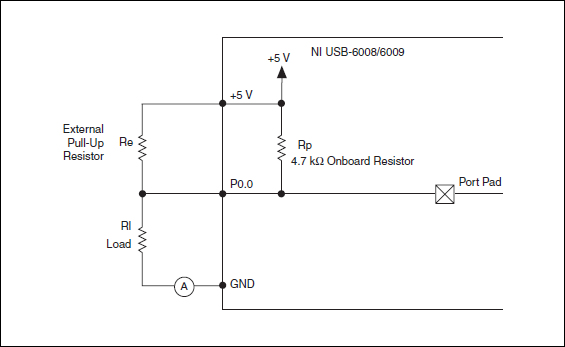
I want to config output digital USB-6009 to + 2.5 V above and 0 V digital output low. I know I can config USB-6009 digital output open collector with resistance to pull-up external, that can be applied with + 2.5 V power source.
My question is: can I use USB-6009 Board + 2.5 V output as the current source of resistance to pull-up? What resistance is a good number for the resistance to pull-up, if I can use this configuration?
Thank you much for the help.
Cathy
Hi Cathy,.
The digital USB 6008 front-end server looks like this:
So, there is actually an internal pullup to 5V 4.7 kOhm resistance when the device is configured to open collector.
If you want to display 0 to 2.5 V, I would look in a resistance of polarization of 4.7 kOhm between c and ground (according to the rest of your tour).
Best regards
-
NI USB-6501 digital output problem
Hello
I use DASYLab v.11 and I'm working on an interface with the NI USB-6501 where I'm putting a digital high on four ports.
With the module "NOR-DAQmx - digital input", I managed to read the digital inputs of the ' NI USB-6501 ".»
It's only the "NOR-DAQmx - digital output" I can't go to work.
Using 'NI MAX' of NOR I have easily can emmit my four LEDs in the way of my High/Low ports.
But not with DASYLab. When you use DASYLab tension on the ports remains unchanged.
Now, I have a switch module, generating 5/0, directly connected to the digital output module, which is assigned to my four output ports for my task.
I also tried with a module of relay between the two without success. I also tried to use 1.5 above instead of 5 without success.
I use the option 'Bus (0/5 supply) for the module "Digital output".
"NI Max", I configured the ports as "active drive.
Any suggestion of what I might be missing?
Thank you
Martin
Hmm, four ports, or four lines?
A port consists of eight lines. Each line can control an LED (ON / OFF ~ 0/5V).
If you have created a task to dig-out to control a port, 5V to this port sending sets all lines of this port to 'high '.
You need to 255 for each line one too high port (at the bit level: 128 + 64 + 32 + 16 + 8 + 4 + 2 + 1).<- eight="">
Or, you can create a dig out tasks to control four lines of a specific port.
Four lanes of the EEG DAQmx DigOut module.
Each of the channels of the modul will feed a single line of the task/device.
Four switches will then turn the lights, or turn off.
Make sure, that the 'bitposition' is the number of correct line (see picture).
-
USB 6008 digital output signal
I am VERY new to LabView and have been racking my brain trying to get digital output of my USB-6008. All I want is to be able to get a signal of + 5 V of my digital output when I click on a button. This signal opens a valve on a system I see so when it is pressed, it must stay open until I press the new button. It seems simple enough to me, but I'm not too familiar with LabView. Help, please!
Stripling07
You must first take the LabVIEW tutorials and then look at the links to get started with DAQmx .
The simplest program would be with the DAQ Assistant. Drop it on your schema, and then select digital output > digital line. Select the line when the wizard has completed, click OK. Wire a Boolean value in a table to build and the output of which is connected to the data entry. That's all. You can test the output of MAX (Measurement & Automation Explorer) with the test Panel. Do NOT test with your connected tap. Your valve may require more current that can provide the 6008.

-
USB-6289 digital output signals setting
I use a USB-6289. I am writing a CVI application that uses this device. I need to put the digital i/o pins as outputs. In the CVI app, I know I can create these tasks with the tools-> create/edit DAQmx tasks. He created this:
Int32 CreateDAQTaskInProject(TaskHandle *taskOut1)
{
Int32 DAQmxError = DAQmxSuccess;
TaskHandle taskOut;DAQmxErrChk (DAQmxCreateTask ("DAQTaskInProject", & taskOut));
DAQmxErrChk (DAQmxCreateDOChan (taskOut, "USB-6289/port0", "))
"DigitalOut", DAQmx_Val_ChanForAllLines));
DAQmxErrChk (DAQmxSetChanAttribute (taskOut, "DigitalOut", DAQmx_DO_InvertLines, 0));* taskOut1 = taskOut;
Error:
Return DAQmxError;
}So this it puts in place but not to write the data. My question is what is the command to write the data?
Also I was wondering if the code source of any example that shows how these commands are made? Is it possible to configure the bits individually? I only need to use 5 of these pins as outputs so t would be coll if I could write that the bits D0 - D4.
Are there documents written on these commands and how they are used?
Thanks in advance
A DAQmxWrite writes the data.
Go to help > examples > material input and output > DAQmx > digital generation.
If you specify the lines instead of a port, you can use as the number of bits you want.
First glance using the ICB.
Maybe you are looking for
-
I have the local and versions at distance of a page is open in two tabs. I change images (keeping the same name in the HTML code) and download the modified image. The tab that displays the remote page does a refresh to show the change. The tab showin
-
New WLan for Satellite L500-01u012 card
The wifi card is dead in my toshiba satellite earlier this week, its out of warranty and toshiba shop wants $200 to replace it with a 2.4 ghz standard card. I'm looking to upgrade to a card capable of 5 GHz in all cases.I found a card that looks good
-
How to keep the liveview on my PC using 2 EOS utility
I just installed EOS Utility 2 on my macbook air and am coupled with my T3i camera, when I go to Liveview via my pc, it keeps turn off after 15 seconds or more. Is it possible to keep this? I keep having to click on preview of the "depth of field" in
-
SG300-28MP power inline or stop?
I have a client with a SG300 28MP and they want to be able to stop or turn on wi - fi when ever. Since I'm AMX touch mounted panels in various places, I want to give them the opportunity, via touch screens to enable or disable, or even to choose pow
-
East-redirection of possible connection when the routing service is disabled?
Possible when connection redirection is the routing service is disabled in win7? I find that this is the case on the following resource monitor. It comes to my ISP. They can redirect my connection like that?