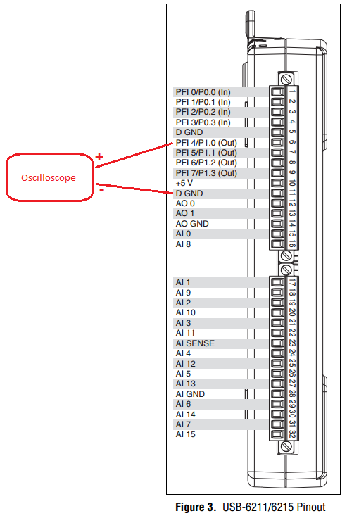
PWM - output meter (PFI4) USB-6211
I managed to control a motor based on PWM signal output via USB-6211 AO continuous. Now, I'm trying to use the Terminal counter instead.
Can't seem to make it work. NA not get a signal when link the PFI4 terminal to an oscilloscope.
I don't know wheather my coding is wrong or does not have my wiring (i.e. of USB-6211 for motor continuous). I need to use the terminal of meter that I used the analog output to a different measure.
Please advice. Attached encodings.
Thank you very much.
Front of conneting to DC motor, make sure first that the PWM is get generated correctly... use oscilloscope.
And have you changed the constant (physical terminals) for your device...?
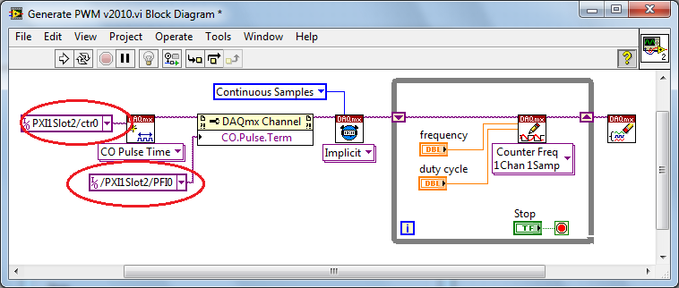
Change to:
Dev1/ctr0 & Dev1/PFI4 and the scheme of connection must be:
Tags: NI Software
Similar Questions
-
Strange analog output of USB-6211
I just got USB-6211 to replace USB-6001 to set the clock to external sampling on analog output for LED lighting control. The part of external clock example works fine, but the analog output voltage is strange. To do self-monitoring, I connected control pin LED to AO0 & AI0 of surveillance in the NI MAX test panel and LED control on the ground at AO - GND & GND HAVE since I have both USB-6001 and USB-6211, I conducted tests on two of them with the same setting of wire. When I generate sine wave - 5V to 5V to AO0 (from NI MAX test panel), USB-6001 can monitor the same signal AI0, but watch USB-6211 - 3, 4V to 3.4V voltage truncated. I did the test separately (wiring one device at a time), so there is no interference between the two devices. USB-6211 past self-calibration and self-monitoring. Also, I did reset devices. I don't know why they would behave differently with the same configuration, and I hope that someone could help with this question. Thank you.
Hi skuo1008,
The USB-6001 can support + / 5 output current my from terminals to analog output, while the USB-6211 box can provide only +/-2 my current output. It is likely that the load impedance is too low, causing the 6211 to hit its current compliance and thus cut the tension. If you try to exchange your load with a resistance of at least 5 v/.002A = 2500 Ohms, you should be able to see the full +/-5V sine wave. I suspect that your DUT has a words 3.4V/.002A = 1700 Ohms impedance. You could use a device with higher output current or use a more current source buffer circuit. If you do not need a bipolar output, you might also consider using digital lines to control the LEDs.
Kind regards
-
Ive got an acquisition of data USB-6211 (and LabView 2009) and Im trying to get the output (5v) device to run a relay on and outside. IM using a tutorial I found on Internet to make the diagram Labview (http://www.pages.drexel.edu/~pyo22/mem639/lab-usb6211DigitalInputOutput/lab-usbDigitalInputOutput082...) and the circuit is simple. I tried to run the DAQ Assistant to test if my output was working, and it is not. I'm not sure if my connections for data acquisition are correct or not. Any help would be useful.
Thank you.
Hello NT_Mech,
Indeed, it is possible that you do not drive enough current for the relay. You can check the specifications of your USB-6211 and see that the digital line will result in a maximum of 16mA. That being said, your relay control current that is needed, you may need to run the two outputs in parallel to offer twice more common provided. Recently, I drove a Soviet Socialist Republic of a Luminary Micro Prototype Board that did not provide enough current as well. In the case of the tat, I was driving the relay by running two lines in parallel.
You can always simplify the software side of things by opening the measurement and Automation Explorer (MAX) and right click on your device and select test panels. "" ' Start ' programs ' National Instruments ' Measurement & Automation then expand devices and Interfaces. Right-click and select Test panels. You can then configure a digital output for your USB-6211 and toggle On / Off and check out.
Best,
-
USB-6211 - digital output not supported?
Hi all
I can't use the USB6211 device port... I use daqmx with Delphi7 API functions.
First of all, I tried this:
DAQmxCreateTask('', @TaskDO);
DAQmxCreateDOChan (TaskDO, PChar('Dev1/port0'), ", DAQmx_Val_ChanForAllLines);
DAQmxWriteDigitalU8 (TaskDO, 1, 1, 1, DAQmx_Val_GroupByChannel, $FF, @written, nil);I had an error in the DAQmxWriteDigitalU8:-200012 (= digital output not supported). (???)
OK, I tried to disable autostart option based on DAQmxWriteDigitalU8 and insert a 'manual' start in the code:
DAQmxCreateTask('', @TaskDO);
DAQmxCreateDOChan (TaskDO, PChar('Dev1/port0'), ", DAQmx_Val_ChanForAllLines);
DAQmxStartTask (TaskDO);
DAQmxWriteDigitalU8 (TaskDO, 1, 0, 1, DAQmx_Val_GroupByChannel, $FF, @written, nil);
DAQmxStopTask (TaskDO);Now, I got the same error in DAQmxStartTask:-200012 (Digital Output not supported, once again). (?????)
I don't understand.. 'Digital output not supported "? USB-6211 has 4 lines! What is the problem?
I want to just turn on and off the lines from code...
-Cs George-
Well, finally I figured out...

Here is the solution:
DAQmxCreateTask('', @TaskDO);
DAQmxCreateDOChan (TaskDO, PChar('Dev1/port1'), ", DAQmx_Val_ChanForAllLines);
DAQmxWriteDigitalU8 (TaskDO, 1, @dummy, 1, DAQmx_Val_GroupByChannel, @bitmask, @written, nil);Digital output lines are on port1! Corrected parameter.
And the part of the interface of DAQmxWriteDigitalU8 had to be changed (in nidaqmx.pas).
I don't know why, but the AutoStart (dummy) parameter in the DAQmxWriteDigitalU8 function is ignored: function always starts task automatically, regardless of the value of autostart. But this isn't a problem for me.-Cs George-
-
Sampling frequency for the output of an acquisition of data USB-6211 card?
Hello-
I use a CGI CMOS FireWire camera to read an interference figure, then using a transformed of Fourier transform spectral interferometery (FTSI) phase recovery simple algorithm to detect the relative phase between the successive shots. My camera has a linear 28 kHz scan rate, and I programmed my phase retrieval algorithm take ms ~0.7 (of a trigger of camera at the exit of the phase). I use the live signal to control a piezoelectric stack, by sending a voltage single sample to the analog output of a data USB-6211 acquisition card.
Send this output voltage increases the time of my loop 4 m, I would really like to achieve a 1 kHz or better sampling rate. Is the problem with my DAQ card or with the processor in my computer? The DAQ cards of NOR can support these speeds?
Thank you
-Mike Chini
Hey Mike,
With USB, your loop rate will be around or under 1 kHz, even on the best of the systems. USB has a higher latency and less determism PCI and PCIe. You can get rates AO one much better sample on a PCI card, potentially a PCI-6221. We have a few HAVE points of reference for targets of RT for PCI, / AO in a loop, you should be able to get similar performance in Windows, but if you do a lot other treatments may suffer from your local loop rates.
Hope this helps,
Andrew S
-
Digital magnification of output using USB-6211
Hello
I'm trying to use the example of LV "Cont writing dig port - Int clk.vi" to generate a model.
But I get the error-200077 on the sample clock. The popup error message suggests
using "we demand", but it doesn't have the choice with the DAQmx.
Any clue? Thank you.
It is correct. USB-6211 case doesn't have a digital time - analog base only. That's why the (63xx) X series cards are supported only for this example.
-
OR USB-6211 is used to count climbing on board TTL
Hello
I'm new to NOR-DAQ cards, and so before buying whatever it is would like to know if it is possible to use a device, NI USB-6211
County and bin amounting to edges of a TTL signal.
What I want to do is to count how many rising edges of a TTL signal I get in a period of 1 ms; a 20 Mhz sampling frequency should be fine.
I would like to use Matlab to control and read the number of edges that are counted as well as in the meantime write and read digital IO ports from the USB-6211.
Is it maybe possible to leave the external TTL signal trigger a 6211 counters, an output then periodically (1 ms) and reset the value of the counter?
Is it possible and if yes, is it a good idea?
Thanks and regards,
Manual
Manual Hi
In order to generate this signal, I could use a second timer mode continuous pulse Train generation, right?
-> Right. You can choose between 2 options
(1) get the signal to another device, for example signal generator or something like that. If you cannot use such a device, you must select the second solution->
(2) generate the 1ms period square wave with the meter of the USB-6211 seconds
I don't know a smart way to generate the 1ms period signal without the software side. You need the software to configure the second counter, route the signal to the second counter for the first counter and so on.
Maybe you can use what is called "panel test" inside the Explorer Measurment & Automation to generate signal. The Measurment & Automation Explorer is a tool provided with the driver for the DAQ cards. The original purpose of this software utility is to configure your hardware, test and so on.
I don't know if it works, but I imagine that the following solution:
You use the test panel called inside the Measurment & Automation Explorer to generate the 1ms period signal (see attached screenshot and http://www.ni.com/white-paper/4638/en). You have no additional program to run the test Panel. Box USB-6211, you use a wire to connect the signal output of the meter of second at the entrance to the first counter. After that, you run Control Panel to test the generation of signals for the seconds counter. At the same time, you start your Matlab program and configure only the first counter. You will need to run the Testpanel all the time if you want to run your measurment.
Not very nice, but maybe the only solution.
Best regards, Stephan
-
Hello
I would like to know if someone could make a recommendation for me. I'm looking to use a material OR PWM output to control 2 motors. I used only for usb 6008 front and concluded that I need a different material for this, but think also that he does not need to be Compact RIO. I need something that does just what I need it to do. Just output PWM for control of 2 motors. The material to drive the motors is not a concern at this time, I'll build later. I just want to see what are the solutions the cheaper for something like this (although I know that this is not "cheap").
Any recommendations would be greatly appreciated.
Thank you
Hey nano,.
If there is feedback involved, your terms of latency will be an important factor in the choice of a hardware configuration. In the order of latency:
USB DATA ACQUISITION< pci="" daq="" (windows="" )="">< pci="" daq="" (rt)=""><>
For the acquisition of data-driven solutions, I suggest to look in the series ( PCIe-6320, USB 6341) X. These have 4 counters that support a wide range of including functionaity to generate PWM signals. If you don't require comments, these commissions have the power output meter in the buffer. If you need your comments, I recommend you to consider alternative Council PCIe latency is much lower than that of USB. RT and FPGA solutions give a latency low but can be quite expensive.
Best regards
-
Lack of charges, USB-6211 with linear gauge Mitutoyo (542 series)
I use a USB-6211 box with a race of 10mm Mitutoyo Linear Gage (542 series, model LGA-110). The Mitutoyo has output similar to an encoder without the time by rev signal quadrature. (B has a phase shift of 90 degrees of A). Signals A and B are airline pilots. I have a k 2 5V to A resistance and another 2K to 5V to B, gives me a minimum of 0.05v and a maximum of 4.75V.
The problem I encounter is that I seem to be missing certain counts that I can't always zero.
I found that if I caress the complete range of meter and the return to zero in 20 seconds, I get a value close to 180 meter microphone. If I press the complete range of meter and the return to zero quickly in a second, I get a value close to 800 micrometer.
If I caress the quick pledge on the compression and rebound more slowly, I find myself with a positive value. I caress the slow pledge on compression and quick on the rebound, I find myself with a negative value.
As I said before, it seems miss me certain counts. With a pulse of each mic of 4 meters, it means I get only 2500 pulses per 10mm. This means that 10mm per second is only 2500 pulses per second. It seems slow for me, so I don't know what would be the problem.
Does anyone have ideas for me to try?
With this type of signal you should not missing any counts. The time base on the box USB-6211 is 80 Mhz and therefore should have no problem to solve your two pulses per train. I have a couple of steps that I would like you to try troubleshooting.
1 to ensure that we plugged the inputs correctly to our DAQ hardware.
2 ensures that we use both the non-reversed or two signals reversed. Do NOT mix or 'type' of the signal.
3 allows you to wire signals A and B in two inputs analog and we will try to read signals to ensure that the sensor is actually be set correctly by the sensor. Be sure to taste pretty quickly--> 10 the frequency of the pulse train. If you race through 10 mm in 1 sec--> 2500 pulses per second--> 25 kHz sampling rate. Allows to check two things. First we have a good TTL signals, and that we get the right number of charges. If you reply to this thread plaese attach a screenshot of the present.
4. we will try different encoder types x 1, x 2, x 4 in the DAQ assistant. The x 2 and x 4 encoder allows the best sensitivity for small movements (which I'm not sure that it is the source of your proplem but it will be a good thing to check). Types of encoder are discussed in more detail in the following developer area: quadrature encoder measures: How To?
Let us know how it shapes to the top.
-
Problem setting up an encoder input and PWM output tasks on CompactDAQ
I use a chassis with a modules 9474 cDAQ-9174 and 9411. I do not think it is important, but they are the cRIO-XXXX modules NOR old provided with a test configuration that has been distributed to early adopters. I use DAQmx tasks in an application (C libraries) to read (angular position) quadrature encoder and drive a motor directly with PWM current (pulse output). For various other needs, my tasks Setup is as follows:
[DAQmx] MajorVersion = 9
MinorVersion = 2
[DAQmxChannel venture 9411 wheel entry/AngularPosition]
CI. AngEncoder.PulsesPerRev = 500
CI. AngEncoder.InitialAngle = 0
CI. Encoder.ZIndexVal = 0
CI. Encoder.ZIndexPhase = a Low high B
CI. Encoder.ZIndexEnable = 0
ChanType = input meter
CI. MeasType = Position: angular encoder
CI. AngEncoder.Units = ticks
PhysicalChanName = cDAQ1Mod2/ctr2
CI. Encoder.DecodingType = X 4
[DAQmxChannel venture 9474 PWM output/PulseOutput]
CO. LTD.. Pulse.IdleState = low
ChanType = output meter
CO. LTD.. OutputType = Pulse:
CO. LTD.. Pulse.HighTime = 5.0000000000000004E - 006
CO. LTD.. Pulse.LowTime = 5.0000000000000002E - 005
CO. LTD.. Pulse.Time.InitialDelay = 0
CO. LTD.. Pulse.Time.Units = seconds
PhysicalChanName = cDAQ1Mod1/ctr3
[DAQmxTask venture 9411 wheel entry]
Channels = venture 9411 wheel input/AngularPosition
SampQuant.SampMode = continuous samples
SampClk.ActiveEdge = Rising
SampQuant.SampPerChan = 100000
SampClk.Rate = 100000
SampTimingType = sample clock
SampClk.src=/cDAQ1/100kHzTimebase
[DAQmxTask venture 9474 PWM output]
Channels = venture 9474, output PWM/PulseOutput
SampQuant.SampMode = continuous samples
SampQuant.SampPerChan = 100000
SampTimingType = implied
RegenMode = allow regeneration
[DAQmxCDAQChassis cDAQ1
] ProductType = cDAQ-9174
DevSerialNum = 0x18B3EC0
[DAQmxCDAQModule cDAQ1Mod1]
ProductType = NOR 9474
DevSerialNum = 0xDEDF40
CompactDAQ.ChassisDevName = cDAQ1
CompactDAQ.SlotNum = 1
[DAQmxCDAQModule cDAQ1Mod2]
ProductType = NOR 9411
DevSerialNum = 0xDEDB24
CompactDAQ.ChassisDevName = cDAQ1
CompactDAQ.SlotNum = 2
Each task works fine on its own (i.e. without the other). The problem is that if I start the task of the encoder first and then the task PWM, the latter causes an error:
Error-89137 occurred to the DAQ Assistant
Possible reasons:
Specified route can not be satisfied, because it requires resources that are currently in use by another route.Source device: cDAQ1
Point source:
80MHzTimebase
Destination device: cDAQ1
Destination
Terminal: Ctr3SourceNeed for resources in use by Source
Feature: cDAQ1
Terminal of source: 100kHzTimebase
Destination
Feature: cDAQ1
Destination terminal: Ctr2SampleClockThe task name: _unnamedTask<61>
I don't know why this is, but if I start the PWM task first, and then the task of the encoder, it also works. I should also mention that initially I was using counter 0 encoder, which caused a shift in the 100kHzTimebase to Ctr0SampleClock, which, according to the ways of device 9411, is not supported. Yet it worked (in itself). I wonder if this is happening under the hood isn't quite what is shown.
What is exactly the conflict and what can do to avoid it? The reasons for having to use specific modes and the settings (for example, the 'continuous samples' with 100kHzTimebase clock) are rooted in various performance and requirements of optimization that were created in a previous version of our software, so I prefer not to take a completely different path, if some small changes would lead us to correct the problem.
I appreciate your help.
Kamen
Hi Kamen,
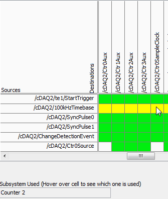
The time base of 100 kHz is not a direct route to the counter sample clocks, the device actually uses one of the other counters to complete the road (the routing table is a little misleading here because it shows 2 meter that one always doing road - in fact it will be any available counter):
So in your case, when you start the task of the encoder, it uses one of the other available counters to complete the configured road (100 kHz to ctr2 sample clock timebase). Of course, she chose meter 3.
Possible workarounds (looks like you have already found one yourself):
1 start the PWM before the task of the encoder task - if the task PWM starts first the counter is already booked and the task of the encoder would choose another available counter to complete its road.
2. explicitly reserve the PWM task before you begin the task of the encoder (if you need to start the task of the encoder first).
3. use cDAQ1/_freqout to generate the clock sample 100 kHz signal and use this instead of routing to the time base of 100 kHz to the counter sample clock.
Change autour counters should also work, but I'm not 100% sure how the unit selects which counter to use for routing (I don't expect change in the future, but if it's not explicitly spec'ed somewhere so I wouldn't take my chances)-if it were me, I would choose one of the other options above.
Best regards
-
How to set the output meter channel to generate a signal pulse using DAQ6008
Hello there I am generating a pulse signal of 100 Hz and a duty of 20% of the 6008 data acquisition cycle using visual studio 2013. I have code that needs to generate this but I'm not sure on how to set the channel output meter. When I run this NI MMAX and my vb error code indicates that the physical channel is not supported. I am a user of data acquisition were first and would appreciate any help offered.
If you look at the USB-6008/6009 User Guide and specifications, you will see that the counter in these devices cannot rely as edges of entry. It cannot generate a pulse.
Lynn
-
Hi, recently, I ordered the DAQ USB 6211, I wonder how do I connect a quadrature encoder to the DAQ meter, I would like to only use a single meter, pin 1-4, my encoder has two channels only, CH A and CH B.
Best regards;
JamalHi jm56789.
I think that the information you are looking for is located on Via MAX (Measurement and Automation Explorer) by creating a task of angular Position for your device.
The default screen that should come has the Configuration tab selected. In the middle of this component, there is a box that lists the "connections". In my case, it says channel should be on PFI0 and canel B on PFI1.
I hope this helps.
Michael G
-
How I ouptut a digital waveform, it has collated and compare it to the original with a usb-6211 box?
I want a digital waveform to a circuit of output, read the return signal and compare the original to the read signal. I use a usb-6211 housing is it possible and if so, how?
Use a comparator "equals sign", mark the post as a solution if you have the makings of what you wanted.
-
How to troubleshoot the work of e/s digital USB 6211
My e/s digital USB 6211 suddenly stopped giving digital output. Board of directors when connected, LED flashes and passes the self-test. But refuses to give any digital output. Can someone help me please?
Thank you for your time. Technician came and found this Terminal connector was loose. Problem is solved
-
Installation of the USB-6211 for DA
I try to use a USB-6211 housing in a very simple system of Visual Studio C++. The final goal is to continuousely output for both channels to 180 samples per second. At this point, I have the following Setup:
DAQmxErrChk (DAQmxCreateTask("",&taskHandle));
DAQmxErrChk (DAQmxCreateAOVoltageChan (taskHandle,
devcmd, //physical channel
' ', //name assigned.
-10.0, the production of //min value
10.0, output value of //max
DAQmx_Val_Volts, release //units
"" scale //custom name
));
DAQmxErrChk (DAQmxCfgSampClkTiming (taskHandle,
"", //source (default OnboardClock)
180.0, //rate in the samples per second
DAQmx_Val_Rising, //active edge
DAQmx_Val_FiniteSamps, finite number of samples (to change) //a
samples_to_write //samples to acquire
));
DAQmxErrChk (DAQmxStartTask (taskHandle));On the last drive, I get the message:
Non-bufferered of NI by the equipment operations are not supported for this device and the type of channel. I can't make any sense of it. Any suggestions?
One of your support staff helped on the phone. It appears as a somewhat obscure command
DAQmxSetWriteRegenMode (taskHandle, DAQmx_Val_DoNotAllowRegen)
It takes to get buffering to work properly. It is a command badly documented, and there is no real indication that this is necessary.
Maybe you are looking for
-
Apple Watch can play music through its built-in speaker?
I do a decent amount of race and the latter I ran with my phone and just play music on the built-in speaker. It's nice to not have to helmet bouncing around and it feels safer because you can hear the traffic and so on. When first announced, I was un
-
If anyone has the serial number of my iPhone, my device is compromised?
can my compromised iphone if anyone has the serial number of my devices?
-
I recently updated two of my Macs to El Capitan, and simply check the box under system preferences/sharing file sharing, I can share files between two Macs - wonderful back. However, I have an old Mac 10.5.8 Leopard who won't get upgrades and I can't
-
Portege M200 - WLan disappears and cannot be reconnected
Hey guys,. I have a toshiba portege M200 computer laptop with Windows XP Professional and SP2. If I turn the WLAN adapt the WLAN network appears once and I can connect and use it without problem. If I disable and enable the wireless network adapter o
-
HDMI Audio driver disappears after the RDP session
I have a desktop PC that I use as a HTPC. It is running xp pro sp3. I have a graphics card Radeon HD5570 I use to connect it to my TV via the HDMI interface. I recently had a car accident and had to rebuild the system disk (re - install windows, driv