5V USB-6229 unstable
USB-6229 is to give significant fluctuations in the measured values when no signal is applied.
To study the problem, I plugged a resistance of 100R between AI0 and AI8 (differential voltage mode)... problem persisted.
Measured 5V (PIN 96)... varies between 2.0V and 4.0V... with sporadic noise.
Input power was measured at constant temperature of 12 v to the input fuse.
Is there anything I can do for this...
Panorama,
You can visit the page warranty and repair for the replacement of related issues
Kind regards
Danny F
Tags: NI Hardware
Similar Questions
-
Double counters in Signal Express with a USB-6229
I have a USB-6229, which I'm running via SignalExpress, and I am trying to simultaneously record two inputs of meter. However, it seems that he has trouble to add the second channel. When I add the first string via signals acquire > DAQmx Acquire > counter entry > Position > angular and select ctr0 channel, he (correctly) lists PFI8 and PFI10 as inputs of channels A and B. However, when I add the ctr1 channel to the same task (via the blue and the button "Add a channel"), he still lists the same PFI8 and PFI10 as input.
On the other hand, if I first add ctr1 then add ctr0 Secondly, it lists PFI3 and PFI11 as A and channel B for the two entries of meter.
How can I get the two counters operating independently?
Thank you
Josh
He realized that I can't run two meters of a single task in Signal Express (unlike, say, two analog inputs). Once I added it as two separate tasks, everything works fine.
Now I have problems of synchronization. Looking through these tips and documentation, it seems that I will not be able to fix this via SignalExpress, so I continue in LabView. I'm having some problems with it, but I'll post in a new thread here.
-
Interrupted the enclosure or usb-6229 during recording and performance data is now not viewable
Hello
I've been recording in Labview SignalExpress 2.5 using the usb-6229 BNC recorder. I was recording on 16 channels with a sampling frequency of 1 kHz over a period of at least 7 hours, while you can imagine a lot of data has been collected. Unfortunately, the power of the recorder was interrupted during recording (but not the PC running Signal Express) and although all the tdms files are present, they will not playback. When I drag the log on in the display area of data, I get the following error message:
' The selected journal is ready for posting. You must wait until the log has finished recording to view it".
If I right click on the journal before sliding above, I get a list of options that is "making visible journal." If I select this, nothing happens at all. If I then right click again, the 'Make visible log' option disappeared. Drag the log on after this step still does not work.
I recorded other newspapers of more than 7 hours that read perfectly well.
If the log files be constantly updated during recording, so that if there is a failure of Rubio, the data are not lost?
The most important thing first, but that is something so that I can play these logs back or are they gone for good? The .tdms file size match those of other file formats that play OK and have the same duration 7hr for registration.
Thanks in advance
Mike
-
How long can I count edges on a USB-6229?
I have a USB-6229, and I want to count the edges using one of the built-in meters. My question is what is the maximum frequency that the meter can the edges of the County of my signal? (I will not mention what my signal frequency because I want to know how to determine the maximum value...)

Hello
Napo2 really seems to ask questions on the highest frequency that can be introduced to the counter to an external source. The best spec for this is the counter 'external clock frequency Base', found in the specifications of 622 x, which claims 20 MHz. The factor limiting here really is the bandwidth of the digital front end on the PFI lines. Internally, the meter is able to count the time base of 80 MHz directly, but a signal to this rate would be completely mitigated by the digital front end of the card if you tried to pass from an external source. The 20 MHz depends on having a square clean wave to come in the card, even if it is not very precise about the time of ascent or minimum pulse widths. You might be able to go a bit beyond 20 MHz, if you have a very clean signal (and conversely, might not be able to hit 20 MHz if signal is not a clean square wave).
This KB previously bound doesn't seem to not relate to the original question of Napo2, and it is also somewhat misleading in general:
The measurement of the period is determined by the frequency source that can be acquired. For Counter/Timer boards, the highest frequency, we can accurately measure will depend on the time base higher frequency for the individual Council.
It's true, in the sense that the higher frequency time base is a factor that plays in the precision of a measurement of the period. However, the KB seems to imply that the maximum that can be measured is the inverse of the maximum time base and does not give further guidance for the determination of the accuracy of the measurement period. A better reference (if you were interested in these things) would be the table in the Manual X series, but even once, this is not really related to the original question.
Best regards
-
Synchronization of a PCI-5114 with a USB-6229
Hello
I'm doing several measures with a couple of scanners OR: the first is a PCI-5114 who reads a signal using the maximum sampling frequency of the 5114. It works currently, and is triggered by a digital pulse at 1 Hz.
Secondly, I have 5 other channels, and I want to measure the maximum voltage on each (analog inputs), at the time the PCI-5114 saves the data. My thought was that I could have the USB-6229 reading data continuously, then 5114 triggers, once I read the files ~ 1000 previous of the 6229. I'm not sure it will work, because I can't be sure that the data the 6229 collects will be the same time as the data that the 5114 collects. Is there a smart way to ensure that is the case? (external clocks, exported triggers the 5114... I do not know what are the options)
For full disclosure, I have 8 digital outputs through the same USB-6229.
Furthermore, if there is a good way to measure the max of each of my 5 channels without having to download 1000's of data points, which would also work.
Any help or advice is much appreciated! Thank you!
Karl
Hi Karl,
The reference of 6229 media triggering (manual link), if you could start it off the same signal of 1 Hz you use to trigger your scope. You can specify the sampling frequency, number of samples and number of samples to relax pre - this should allow you to correlate your acquisition on the map of data acquisition to the time window even that your scope is acquiring data. The clocks would still be independent, but I don't think it matters too much because you are triggering the same external signal every second.
After that the DAQ trigger card you will need to re - start the task in software to re - arm (something like in This example), but the interval of 1 Hz should be more than enough to do this.
Best regards
-
OR USB-6229 unused outputs floating
Hello!
I have a DAQ NI USB-6229 map and I want to generate a current (I use shunt resistors) and inject it into a resistor network. While doing this I also want to measure 6 potential to a few nodes on the network. This procedure is then repeated four times, and for each new set of measures, I want to change the current node injection.
I managed to make a flat sequence version that works sort of "semi-automatic", that is. I manually move the connector for the injection of current corn,
now I would like to program to do this for me. The problem I face then is that I have to connect to all channels of analog output to my network and I can't make it floating. So I need to get the voltage on shunt temporarily "unused" zero resistance and make them floating. I was thinking of doing a while loop which regulates the voltage, but then how to leave the loop everything with it regulate the voltage?
Is there maybe a solution to this problem?
Thanks in advance!
/
EmanuelIt is much clearer. Thank you.
If all of your applied voltages, including tensions applied to generate the currents I1 and I2, are positive, you can then use diodes to rpovide isolation. You are already set up to measure the tension, it should be possible to offset decreases of voltage diode.
Another approach would be to exploit the tensions in potentiometric mode to make zero currents. Let me define some terms using your diagram: V1 = voltage applied to create the current I1. V1n = input to the network in the I1 circuit voltage when I1 current circulates. Of the law of Ohm I1 = (V1 - V1n) / Rshunt. Similarly V2 and V2n refer to tensions related to the current I2. To define the I2 = 0, V2 = V2n. Of course the tension to V2n will depend on the voltage and current elsewhere in the network.
To join the operation points you want will require an iterative process. Consider the case where I1 = 1 and all other currents are zero. The procedure might look like this:
1. apply the V1. Set all tensions to zero.
2. measure the V1, V2, V1n, V2n...
3. calculate all currents.
4 calculate all voltages to change the values you want, using the assumption that tensions n V [i] do not change.
5 connect the calculated in step 4.
6 repeat step 2 until the new tensions calculated in step 4 are close enough to the values of the previous iteration.
If the network is linear, but the values are not too extreme, it will probably work. If it is not the case, you may need to scan the network to see if its admittance matrix is singular, or the range of values is too broad.
A state machine would be a good program architecture to implement an algorithm like that.
Lynn
-
I am trying to build a VI to control a single relay to open and close 5 valves in series pour.5 seconds. I have a USB-6229 Control Board to do so. I am new to labview and need help the code for the VI. Any suggestions would be helpful.
Try this...
-
Linux drivers for the acquisition of data USB-6229
I would use a USB-6229 with Linux and support driver selection guide said that this model is not supported. However, the 6218 and others are supported. Is it possible to use 3. 5B pilot defined for a USB-6229 with reduced functionality? Is it possible, with some basic Linux knowledge codification driver of change 3. 5 b drivers to work with a USB-6229?
Kind regards
Craig
Hi Craig,.
That is right.
Best,
-
With the help of several outings on NI USB-6229
Hello
I have a question about the use of several output (input) on NI USB-6229. I request of programming where I use a few digital, digital inputs, outputs some analog outputs and inputs. Initialization of all the ports that I have in a Subvi, which lies in a loop for I control settings on the other for loop by using notifications. Problem is that this outpust is really slow (or reading entries), I want to say in my main loop I setting button, but it takes at least 1 s to change my outings (even with reading entries)? So I am wonderig what I am doing wrong. Can plesae you tell me what is the best way how to control several different ports?
OK, so my whole program structure is like this:
In primary Vi, I have a loop that subvis in other control loops. One of the Subvi is Subvi whichchange parameters at initialization Subvi. The structure on the photo. Please help me because I really don't know where is the problem. I use two converters AD / DA more and some machines that I am targeted by using the RS232 but it NEITHER original is the slowest.
PS. If I turn on only parameter Subvi loop everythinf is much faster.
OK problem with loops slow fixed http://forums.ni.com/t5/LabVIEW/Slow-parallell-loops-with-DAQ/m-p/1698988#M601731.
-
Temperature measurement and the CJC using thermocouples on a USB - 6229 BNC
Hello
I'm trying to get the measurements of temperature using type K thermocouples on the box nor usb-6229 BNC. SignalExpress software doesn't let me choose 'Built In' to the Source of the CJC. So, I must select 'Constant', which means that I then have to follow the evolution of the temperature during the day with a separate meter and adjust the value of CJC accordingly to maintain an accurate reading. Is there a way around that to avoid having to monitor the room temperature at the junction?
Thanks in advance
Mike
Hi Mike,.
It seems that you have managed to find a solution for you have this problem, which is great news.
However, for future use, if you had bought the 6229 with massive ending (rather than the interface BNC) then you might have interfaced unit with a block of connection SCB-68 (see link)
http://sine.NI.com/NIPs/CDs/view/p/lang/en/NID/1180
The SCB-68 has a CYC source built-in, so you might have used in conjunction with 6229 (mass layoffs).
A bit of in the way, but I thought you may be interested.
Best wishes to you all
-
Brooks connection using usb-6229
Thanks in advance.
I've updated your VI. I never used DAQmx Express screws, but I hope that it will work. Please note that channels playback mode HAVE changed to 1 sample (on request).
I can't check your Custom Scaling. If you do not see the expected flow, check that scales in the DAQmx express properties VI. If missing the definition of the scale, just
choice for signal input and output range of 0 to 5 volts, or anything that requires your MFC. -
HI, I connect acquisition of data USB 6229 quadrature encoder, I connect CH A PFI 0/P1.0 or PIN 73 and PFI 0/p1.1 or PIN 74 and I'm setting them up as a counter or a desk reading in. The USB6229 of data acquisition is not read these signals as a counter. How I would read the counts of a quadrature encoder, using materials DAQ 6229.
Regads;
JH
The fact that it is the reading of thousands and millions usually means that there is noise on the signal that is picked up as the account when it really shouldn't be. To correct this, you must activate digital filtering:
See the example:
Use the digital meter Debounce filter
and page 7-32 to 7-33 of the M series user manual for details of what a digital filter is and the different settings available for the 6229.
Activation of the filter will get rid of the very high frequency on the digital line noise and must get rid of the extremely high values and instead to give a good account of 256 / rev.
-
Properties of the scanclock exported by Matlabs addClockConnection() on a 6229 OR USB (BNC)
With the Matlab DAQ Toolbox, it is possible to export a scanclock by addClockConnection() (see http://www.mathworks.de/de/help/daq/ref/daq.session.addclockconnection.html for an example of code base).
However, I found no information on properties signal exported on the NI USB 6229 (BNC), for instance frequency, amplitude, duty cycle, etc., or in the documentation, or on the web or in this forum.
I would be very happy if someone can point me to the documentation for the properties of scanclock.
Hello
All channels in a MATLAB session running at the same pace. So, if you create a session', s.Rate would be the rate of your acquisition or production. the 's.addClockConnection' method allows you to import or export a clock to analysis for synchronization purposes. The syntax below allows you to export the session of 'PFI0' on an external device clock. You can probably find documentation on the Web site, OR to the properties of the embedded clock signal, but it seems to be a pulse of 5 volts running to the session rate - which is typical to synchronize the devices together.
s.addClockConnection ('dev2\pfi0', 'external', 'ScanClock');
If you need duty cycle 50%, you must create your own clock using a channel of meter output as you did above. If you connect the clock to the GET, it can use it; and if you need your equipment OR to dribble the clock output of counter (instead of the clock on board), you would also import counter signal output in the session and be sure to set the rate of session to match the output frequency of the counter. Assuming that s.Channels (2) is your output channel of the meter, the code below imports terminal scan on the same clock as the meter output channel, so no extra wiring is necessary.
s.Rate = s.Channels (2). Frequency;
s.addClockConnection ('external', ['dev2\' s.Channels (2).]) (Terminal Server], "ScanClock");
This allows the device OR both your GET to run on the same clock. You can also have your session export a trigger to start with the syntax simillar to the above to make sure two devices on the same edge of clock.
s.addTriggerConnection ('dev2\pfi0', 'external', 'StartTrigger');
I hope this helps.
Kind regards
whemdan
The MathWorks
-
How update tasks by programming every time OR USB peripheral is connected?
Hello. Do I know how the NI Max task can be updated the programtically each time than another USB device of NOR is fixed, without any user to do something?
I created some taks for NI USB-6221, however, when the case NI USB-6229 is attached, 2 Dev appears instead of 1 Dev.
Can we create a program which automatically update the NI Max task before the effective operation of the new device?
Please notify.
Thanks in advance.
Clement
Hi, if I understand you correctly, if you use the code I showed then no matter what the number of Dev. It is only important if you have more than one device connected to the PC of the same model. If you have only 1 device connected at a time then the code I'm running allows you to retrieve the number of Dev for the device and your task code can then use it. I do not think it is necessary to change the assignments of Dev in MAX.
-
Using a counter with FiniteSamps and one with ContSamps
I am using 2 counters on the NI USB-6229 (or USB-6259), case where a counter is implemented for FiniteSamps and another for ContSamps. I have the following MeasurementStudio code:
ErrChk DAQmxCreateCOPulseChanTicks(hCnt0, "Dev1/ctr0", "", "20MHzTimebase", DAQmx_Val_Low, 0, 400, 400);
ErrChk DAQmxCfgImplicitTiming(hCnt0, DAQmx_Val_FiniteSamps, 100);ErrChk DAQmxStartTask (hCnt0);
ErrChk DAQmxCreateCOPulseChanTicks(hCnt1, "Dev1/ctr1", "", "20MHzTimebase", DAQmx_Val_Low, 0, 400, 400);
ErrChk DAQmxCfgImplicitTiming(hCnt1, DAQmx_Val_ContSamps, 2);
ErrChk DAQmxStartTask (hCnt1);
When I run it, I get an error-50103 "the resource specified is reserved". If I change the FiniteSamps to ContSamps on the first counter, everything works fine.
If I use only one counter with FiniteSamps, everything works very well.
Is this a bug in DAQmx or the use of double counter on M Series devices is limited to ContSamps?
VIC
Hey Vic,
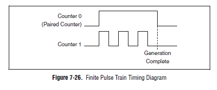
It is actually planned on a device of the M series. Here's a time diagram of the M Series user manual which might make this a little clearer:
The device uses actually one counter for the other door so the result is a generation of finite pulse. If you can provide the door from another source, you can configure a generation of continuous pulses on two counters and their door (DAQmx calls it a "relaxing break") of this external signal.
You can also look at the use of the digital I/o correlated to generate impulses over multiple (up to 32 lines on your 6229 and 6259). You could use one of the counters to generate a time base for digital lines and build the waveform as a result.
One thing to note is that our new X series cards can generate a generation of impulses finished on a "single" counter (it was actually a paired internal counter that allows this). There are four accessible counters by the user on the X series devices, which means you could generate four pulse trains finished.
Best regards
John
Maybe you are looking for
-
Fell and custom light up the screen Black w / a hack
IT does not work there is a hack and looks as if there's any pressure at this place it will not turn on doing anythin Ive tried everything and idk what to do please help me!
-
NETGEAR AC1900 R7000 several Xbox those open NAT Type
Hi all What is the best solution for those multiple Xbox on the same network. I have two Xbox. My question - get an open NAT Type on both those of Xbox. Both systems have a NAT open but not for multiplayer games. More specifically, black ops 3. I hav
-
Could not load file or Assembly runtime being more recent than currently loaded run time
I've recently upgraded to TestStand 2010 and Visual Studio 2010 TestStand 4.2.1 and Visual Studio 2008. I now get the following error in the analysis of the sequence for all calls to my .net dll. "Step"My_StepType"not loadable module. Could not load
-
Sony PC Companion Z3 issue on Windows 8.1
When I connect my Z3 with Windows 8.1 PC via USB, the phone will ask you wheather I want to install the software on my PC. I say 'Yes', but nothing installed on my PC or do nothing. Then I discovered the Sony Xperia care download and installed on my
-
We have a new laser jet 400 MFP all-in-one at our reception and have been very happy with it, except for a problem that we have at all times. When we receive a fax it will recognize it and receiver say page 1, and then he began to compose the 102 an