Acceptable external sample of NI 5772 clock
Hello support forum,
Is it possible to use the module to adapt OR 5772 with an external sample clock that does not have a constant frequency (it is always in the range of 400 to 800 MHz, well), and is always turned on?
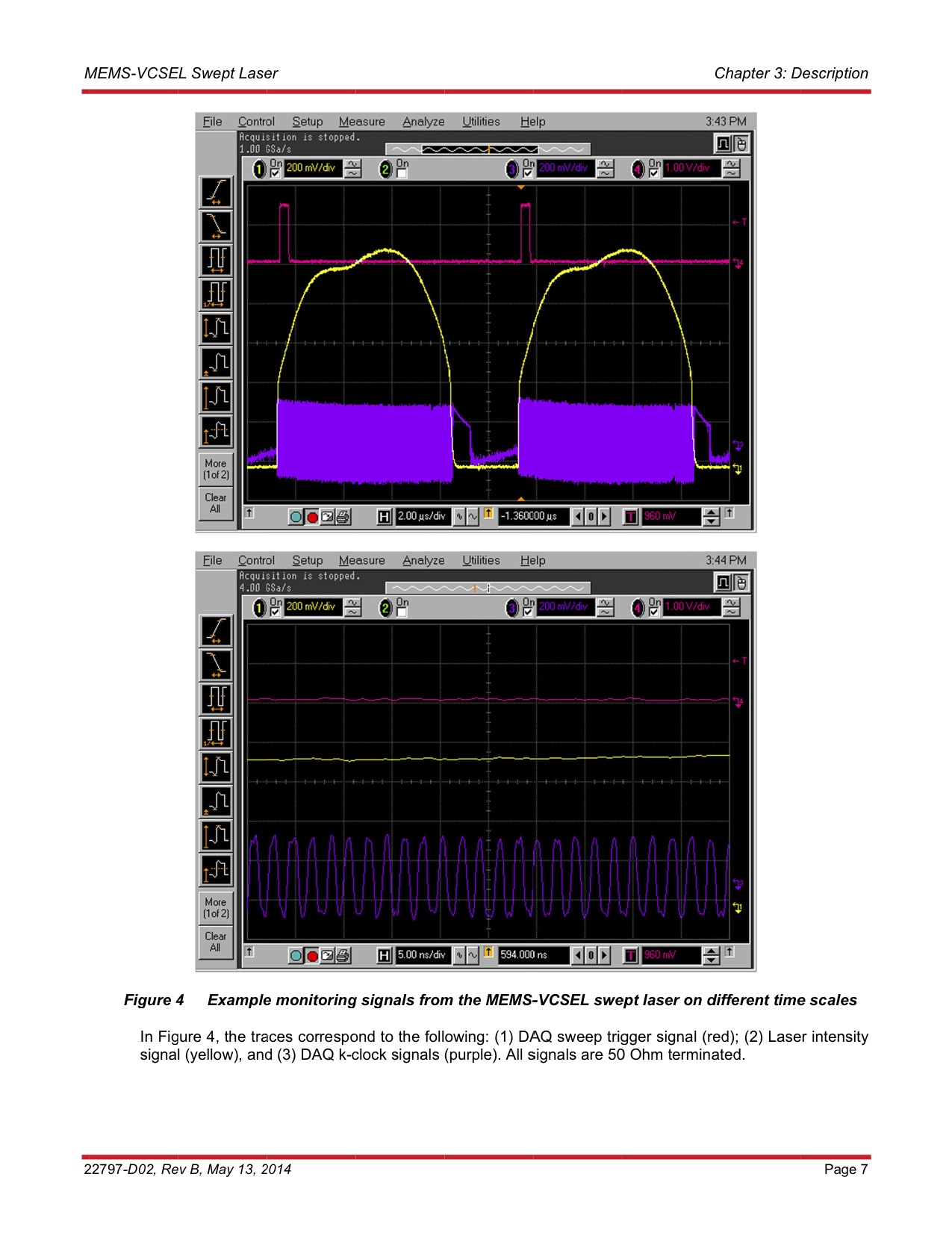
An illustration of the clock signal may be more useful. Here is a link to a PDF file containing a description of the instrument that generates the clock signal. The plot of the clock signal is shown on page 7, it's the purple wave form (referred to as "(3) DAQ k-clock signals" in the text below the numbers).
http://www.Thorlabs.com/thorcat/22700/SL1310V1-10048-manual.PDF
I have attached a screenshot on page 7 in this post where the PDF is inconvienent.
Page 7 contains two numbers. The top figure illustrates what I mean when I say that the clock is not always 'on '.
The clock signal is supposed to be close to 500 MHz, but it is not necessarily always this frequency. The frequency depends on the device. The device is a source laser scanned. Each "sweep" may cause a slightly different frequency, even within a single shot.
I can provide many more details on my application if necessary.
Thank you for your help.
The CLIP that we ship with the 5772 requires a persistent clock that maintains a relatively stable frequency. If you need to use a 5772 with a variable frequency clock that is not persistent, then you need a CLIP custom. According to the specifications of your application, this may or may not be possible. You will need open a service request for more information.
Tags: NI Software
Similar Questions
-
Measurement error of the County of edge by using the external sample clock
Hello
I'm trying to measure the number of edges (rising) on a square wave at 5 kHz with a generator function on a device of the NI PCIe-6363. I configured a channel of County of front edge of counter at the entrance of the PFI8 device. I use an external sample clock that is provided by the output of the meter of a NI USB-6211 housing channel. If I acquire for 10secs then ideally I would expect to see a total of 50000 edges measured on the meter inlet channel. However, my reading is anywhere between 49900 and 50000.
When I use the internal clock of time base to measure the edges, the measure is accurate and almost always exactly 50000. I understand that when you use the external sample clock, the precision of the measurements is subject to noise level of the clock signal. However, I checked the clock signal is stable and not very noisy. Any reason why there is an error of measurement and how tolerance should I expect when using an external sample clock compared to when you use the internal time base clock?
Also, what is best clock Frequency (with respect to the frequency of the input signal) when using an external clock?
Thank you
Noblet
Hi all
Thanks for all your sugggestions. I was using an input signal with a function generator which had a range of 8V. It turns out that the reduction of the amplitude to 5V solves the problem. I was able to get accurate numbers with the 6211 external clock.
Thank you
Noblet
-
External sample clock change takes a lot of time on the SMU-5186
Hello
I use the external Lv - niScope EX Clocking.vi example to define SMU-5186 using an external sample clock. However, it takes a long time, 5-6 minutes, before I can get the first block of data acquisition.
Then I run the example 'niScope EX Acquisition.vi Configured' to switch to dashboard clock. There are also 5 to 6 minutes on the first acquisition.
I think maybe the SMU-5186 made some calibration when I change the source of the clock.
Anyway is to ignore the calibration? Or make it faster?
Thank you very much
Yiming
Yiming,
Delays in acquisition are caused by calibration routines that must be performed on the engine to sample (ADC) every time that changes sampling rate. This ensures our justified precision specifications.
I don't know if you've noticed also calibration of Power-Up, which will take 5-10 minutes to complete when the unit is turned on. This is mentioned in our specifications at page 18:
http://www.NI.com/PDF/manuals/373257b.PDF#page=18
I hope this helps.
Nathan
-
An external sample clock between sharing arrangements
I need to acquire samples of 2 separated Renault M series (PCI-6254). My master device receives a sample of 8 on PFI0 KHz clock. Is it possible at the root of this clock of the master to the slave via a RTSI cable device?
I looked through the forum and the sample programs, but have only seen examples in which the master clock on board the aircraft happened to the slave.
It is possibe to synchornize device slave the master clock to external sampling of the device?
Thank you
ANT1
ANT1,
Fortunately, most of the time something that can be done in DAQmx in LabVIEW can be done in ANSI C using the appropriate function calls. I have listed the following steps of the program example LabVIEW and retouched to remove anything that it is not suitable for the DAQmx configuration. I'm sure it should work for you.
Steps to follow:
1 create a channel of analog input voltage for the master and the slave.
2 set the synchronization parameters. For the master, select the source of the external sample clock. Set the source AI/SampleClock of the master for the slave device. (Note: sample of the master clock is automatically routed through the cable RTSI.)
3. for the slave, set the Source of the trigger to the AI/StartTrigger of the master device. This will ensure that both devices start sampling at the same time. (Note: the trigger is automatically redirected via the RTSI cable.)
4. call the start task to start the acquisition. (Note: start slave task before the master task.)
6. read all waveform data.
7. call the clear task to stop the acquisition and clear the task.So, essentially, the value of the task of the slave to the top in the same way as you would for the synchronization of clocks on board, but configure the task to master as you would for an external clock. This will automatically share the external clock and trigger on the line of the RTSI.
-
NI6602 pulse width measurement: do I have to use an external sample clock?
Hello
In the example .NET 4 "MeasPulseWidthBuf_SmplClk_Cont", it is said in the comments that:
An external sample clock should be used.
Hi mola.
This specific example measures of sample-clocked pulse width. This type of measure is supported only on new hardware such as the X series cards and will not run on the 6602.
Your application that you have linked uses Implicit timing, which means that the signal is using the sample clock. In other words, at the end of each pulse duration which can be measured, the sample is deterministic locked in. So you end up with a table in the buffer of each pulse width which is seen by the meter.
Best regards
-
Synchronization of analog and digital output with the external sample clock
Hello
First of all sorry for my English, I will try to explain what I want to do.
I want my PCIe-6321 to send two custom signals (modification sawtooths) on a mirror controller. I would also like to generate output with my card at the beginning of each tooth of saw. Everything must be synchronized with an external k-clock signal of 100 kHz. The idea is that whenever the PCI receives a trigger to external clock, it sends two analog output voltages and when he received 1024 clock ticks it will also send a pic of triggering TTL. What I do is first prepare the map and after that in a loop sending and modifing the output values of the two signals and at the same time send a digital signal Boolean in each arch, so when's done it 1024 iterations of the loop I send an event to the digital port. Attached you can see.
The problem is that I don't know how to synchronize both. Can I use the sample clock just to the analog output? I can use sample for the two outputs clock, or do I need to use the output of the meter? If don't know how to use it here.
If I do nothing else bad/wrong, I would be grateful for feedback.
Thanks in advance,
PabloI don't know how but I find the solution. I'm generating more than a positive value (as I was triggered maybe very fast the oscilloscope has been absent there). If I put the sample clock of digital output to use the sampling/ao/Dev1 clock that it doesn't, but if I put to use the same source as the OD (terminal where my external clock is connected), but the trigger to start the DO to be Dev1/ao/StartTrigger this works. I don't really know why, but it does.
Thank you for your patience and your help. I put here the final code.
-
PXI-5122 external sample clock
Hi csk,.
I was wondering if you could clarify how
you want to take samples. Am I right in taking 30 000
sets of 150 samples each, or do you mean that you take 150 sets of
30 000 samples each (since 30 000 periods of 60 MHz clock corresponds to)
less than 90% of a 1.8 kHz signal)? In both cases, the current method you
are using only will acquire a single record each time by
the loop, and so you will be limited by how fast you can retrigger in
software.For your application, it looks like you want
need to perform a multi-record acquisition, which will allow you
specify what condition to trigger off of and how many samples of
acquire whenever the trigger occurs. In this way, each 'transition' of the sawtooth wave is considered to be a single record, and you buy several different corresponding records whenever a rising edge trigger occurs. I think you can accomplish
exactly what you need with only a slight modification to the niScope
example of expedition "niScope EX Multi Record go get more available»
Memory.VI"(se trouvant àles Start» Programmes» National Instruments» NI-SCOPE)"
("Examples). With this VI, you can specify that each record you want to
have a record length min to 30 000 samples (or 150 samples, if it
the case) and you want to acquire 150 records (or 30 000 if this)
that is the case). The only big change that you need to do is to
change the trigger VI set up to be a digital dashboard rather trigger
only an analog trigger. With that and a few other changes (i.e.:-)
setting the external clock), you should be able to accomplish what
You need. Please let me know if I have explained well and if my
assumptions are correct. Thanks and good luck! -
Looking for USB DAQ for AO using the external sample clock
Hi all
I'm looking for a cheap solution for the acquisition of data to select the AO using an external digital signal as sample clock, and I just realized that the USB-6001 is not a good candidate. Please someone remind the cheapest USB version for this task? There no need for high sampling rate. Thank you.
Define cheap and low sampling rate. You've already been told on the 6211.
-
with pulse width measurement external sample clock
Hi all
I use a NI 6220 (programming with ANSI C) Board and I would like to make a "unique pulse width measurement' by using a signal from the outer door and an external signal source.
The program and the card with the help of the "DAQmxCreateCIPulseWidthChan" command works only partially as expected. Namely, the outer door has worked, but the map uses the internal time of 80 MHz base signal instead of the external source connected to the source by default PIN (PFI, 8).
I tried send an another PIN PFI on the default source pin using the command 'DAQmxConnectTerms', but this did not help either.
Obviously, I'm missing something...
Best, Uli
Hi Uli,
I posted in your thread here.
Best regards
-
Sample USB - 6343 Counter clock
I use a USB-6343 CTR0 to measure the angular position. I expect to ~ 1 million encoder pulses (or account) per second. What USB-6343 clock signal would be preferable to use the counter sample clock?
Dar Hi,.
At what resolution do you need measure the angle?
One of my colleagues has compared the maximum sampling frequency on the counters of series X USB to be approximately 8 MHz for a single channel, continuous operation for 10 minutes. However, if the signal that you intend only generates pulses at 1 MHz, 8 MHz rate seems unnecessary because you will receive the same reading several times.
Concerning the two methods you mentioned, either would not be possible:
(1) you could count the external signal and sample at regular intervals. For example, if 10 kHz sampling you'd expect to see ~ 100 strokes per sample if clock signal is 1 MHz.
(2) you can also use the meter to count a time base internally (for example 100 MHz) and the sample out of your external signal. Thus, during a period of your external signal, you expect to see 100 graduations of the time base.
It seems that what you're trying to do is to measure the frequency of your encoder at regular intervals. To do this, I suggest you actually a variant 3. X series cards support a measure of frequency clocked for example (see the X Series user manual). The card has two occurrences of the external signal as well as occurrences of the internal time base known and uses it to determine the frequency. The one caveat is that the signal you are measuring the encoder must be at least two times faster than the sample clock signal. I suggest to use Freq Out or another counter to generate the sample clock.
Best regards
-
DaqMX wait the next sample causing slow down Clock.vi
Hello
I have a question about the proper use of DaqMX wait for next sample clock.
I read channels analog voltage on a map or pcie-6259.
I would like to read as soon as possible make your comments between each of these points of single data points.
I wish I had an error generated if I miss a data point.
From reading the forums, I've gathered that the best way to do it is using the Timed Single Point material.
A simplified program that I use to test this is attached.
If I remove the DaqMX wait for next sample Clock.vi, my program seems to work.
I added a counter to check the total time is as expected.
For example, the program seems to work at the speed appropriate for 120.
However, without that vi, it seems that the program does not generate a warning if I missed a sample.
So I thought that the next sample clock waiting vi could be used to determine if a single data point has been missed using the output "is late."
However, when I add inside as shown in the joint, the program seems to slow down considerably.
At high rates as 120000, I get the error:-209802
14kHz is the approximate maximum rate before you start to make mistakes.
My question is: is this the right way to check a missed sample? I don't understand why the wait next sample Clock.vi is originally a slow down. Without this vi, the program does just what I want except that I do not have strict error control.
My confusion may be based on a lack of understanding of real-time systems. I don't think I do 'real time' as I run on an ordinary pc, so maybe I use some features that I wouldn't.
Thank you
Mike
Mike,
You should be able to read to return delays errors and warnings by setting the DAQmx real-time-> ReportMissedSamp property. I think that if you enable this, you will see errors or warnings (according to the DAQmx real-time-> ConvertLateErrorsToWarnings) in the case where you use read-only. I'm a little surprised that you have measured your application works at 120 kHz without waiting for next sample clock (WFNSC), although I'm not surprised that it would be significantly faster. I think if you call read-only, you'll read the last sample available regardless of whether you would of missed samples or not. When you call WFNSC, DAQmx will always wait for the next, if you are late or not sample clock. In this case, you will wait an additional sample clock that is not the case in read-only. Once again, I expect that, in both cases, your loop would not go to 120 kHz.
Features real-time DAQmx (hardware Timed Single Point - HWTSP) are a set of features that are optimized for a one-time operation, but also a mechanism to provide feedback as to if a request is following the acquisition. There is nothing inherently wrong with using this feature on a non real-time OS. However, planner of a non real-time OS is not going to be deterministic. This means that your app 'real time' may be interrupted for a period not confined while the BONE died in the service of other applications or everything he needs to do. DAQmx will always tell you if your application is to follow, but can do nothing to guarantee that this will happen. Thus, your request * must * tolerant bet of this type of interruption.
There are a few things to consider. If it is important that you perform the action at a given rate, then you should consider using a real-time operating system, or even with an FPGA based approach. If it is not essential to your system, you might consider using is HWTSP, where you do not declare lack samples (DAQmx simply give you the most recent example), or you could avoid HW timing all together and just use HAVE request to acquire a sample at a time. What is appropriate depends on the requirements of your application.
Hope that helps,
Dan
-
I use the PCI-6723 card and I am trying to produce a model of waveform using the analog output channel. The wave consists of 5 different voltage levels. The main problem is that the first 4 voltage levels are supposed to have 926 microseconds time intervals and the time interval the last voltage level is supposed to be 1,296 milliseconds. In addition, the waveform must be triggered on the trailing edge of a sample clock of 200 Hz with a 0.1% Duty Cycle. Is it still possible? If so, any help would be greatly appreciated. Thanks in advance!
Here is what I currently have, but it does not fulfill my purpose.
 int32   written;
    float64 data[5] = {-0.23, 0.38, 1.12, 1.78, 0.10};  //volts
    //long  time[5] = {  926,  926,  926,  926, 1296};  //microseconds

    // DAQmx Configure Clock
    DAQmxErrChk (DAQmxCreateTask("",&taskHandleFRQ));
    DAQmxErrChk (DAQmxCreateCOPulseChanFreq(taskHandleFRQ,"Dev3/ctr0","",DAQmx_Val_Hz,DAQmx_Val_Low,0,200,0.001));
    DAQmxErrChk (DAQmxCfgImplicitTiming(taskHandleFRQ,DAQmx_Val_ContSamps,1));

    // DAQmx Start Code
    DAQmxErrChk (DAQmxStartTask(taskHandleFRQ));

    // DAQmx Configure Code
    DAQmxErrChk (DAQmxCreateTask("",&taskHandle));
    DAQmxErrChk (DAQmxCreateAOVoltageChan(taskHandle,"Dev3/ao0","",-10.0,10.0,DAQmx_Val_Volts,NULL));
    DAQmxErrChk (DAQmxCfgSampClkTiming(taskHandle,"/Dev3/Ctr0Out",1000.0,DAQmx_Val_Falling,DAQmx_Val_ContSamps,5));

    // DAQmx Write Code
    DAQmxErrChk (DAQmxWriteAnalogF64(taskHandle,5,0,10.0,DAQmx_Val_GroupByChannel,data,&written,NULL));

    // DAQmx Start Code
    DAQmxErrChk (DAQmxStartTask(taskHandle));
Bingo. This code seems to work much better. Looks like I had to reduce my number of samples per 1 to fit the waveform desired in 5 milliseconds of the sample clock delay.
However, if someone knows a better way to achieve these results, I am open to all ideas.
void CDevDlg::OnRdr1e1() { float64 data[4000]; float64 volt[5] = {-0.23, 0.38, 1.12, 1.78, 0.10}; //volts int x=0,d; for(int v=0; v<4; v++) { for(d=0; d<741; d++) { data[x++] = volt[v]; } } for(d=0; d<1036; d++) { data[x++] = volt[4]; } // DAQmx Configure Clock DAQmxErrChk (DAQmxCreateTask("",&taskHandleFRQ)); DAQmxErrChk (DAQmxCreateCOPulseChanFreq(taskHandleFRQ,"Dev3/ctr0","",DAQmx_Val_Hz,DAQmx_Val_Low,0,200,0.001)); DAQmxErrChk (DAQmxCfgImplicitTiming(taskHandleFRQ,DAQmx_Val_ContSamps,800000)); // DAQmx Start Code DAQmxErrChk (DAQmxStartTask(taskHandleFRQ)); // DAQmx Configure Code DAQmxErrChk (DAQmxCreateTask("",&taskHandle)); DAQmxErrChk (DAQmxCreateAOVoltageChan(taskHandle,"Dev3/ao0","",-0.5,2.0,DAQmx_Val_Volts,NULL)); DAQmxErrChk (DAQmxCfgSampClkTiming(taskHandle,"",800000,DAQmx_Val_Rising,DAQmx_Val_ContSamps,4000)); DAQmxErrChk (DAQmxCfgDigEdgeStartTrig(taskHandle,"/Dev3/Ctr0Out",DAQmx_Val_Falling)); // DAQmx Write Code DAQmxErrChk (DAQmxWriteAnalogF64(taskHandle,4000,1,10.0,DAQmx_Val_GroupByChannel,data,NULL,NULL)); } -
672PCI 6723 error when you try to generate a signal with the sample of 20 kHz clock
I have a piece of code that worked successfully on the PCI-6224 map, but when I tried to implement the same code on the card PCI-6723 I ran into problems.
Here is the code I use:
ManchConversion6723();//produces SendIt array of series of 1s/0s

// DAQmx Configure Clock
DAQmxErrChk (DAQmxCreateTask("",&taskHandleFRQ));
DAQmxErrChk (DAQmxCreateCOPulseChanFreq(taskHandleFRQ,"Dev3/ctr0","",DAQmx_Val_Hz,DAQmx_Val_Low,0,20000,0.5));
DAQmxErrChk (DAQmxCfgImplicitTiming(taskHandleFRQ,DAQmx_Val_ContSamps,72));

// DAQmx Configure Digital Output
DAQmxErrChk (DAQmxCreateTask("",&taskHandle));MessageBox("D");//vj
DAQmxErrChk (DAQmxCreateDOChan(taskHandle,"Dev3/port0/line0","",DAQmx_Val_ChanPerLine));MessageBox("E");//vj
DAQmxErrChk (DAQmxCfgSampClkTiming(taskHandle,"/Dev3/Ctr0InternalOutput",20000,DAQmx_Val_Rising,DAQmx_Val_ContSamps,72));

// DAQmx Write Code
DAQmxErrChk (DAQmxWriteDigitalLines(taskHandle,72,0,10.0,DAQmx_Val_GroupByChannel,SendIt6723,NULL,NULL));

// DAQmx Start Code
DAQmxErrChk (DAQmxStartTask(taskHandleFRQ));
DAQmxErrChk (DAQmxStartTask(taskHandle));
When I get on the DAQmxCfgSampClkTiming line, I get an error stating:
DAQmx error: measurements: request the value is not supported for this property value.
Property
 AQmx_SampTimingType
You asked: DAQmx_Val_SampClk
You can select: DAQmx_Val_OnDemand
Task name: _unnamedTask<0>
State code:-200077
I think that the problem comes from the variable of the source of the function. I'm just tring to send the data to the frequency of 20 kHz.
Any help would be greatly appreciated. Thanks in advance!
Too bad. The impression that the PCI-6723 does not contain correlated DIO channels. In other words, examples of clock cannot be linked to the DIO channels allowing the generation of digital waveforms. According to the AO Series user manual, this applies to the NI 6731/6733 only. The mistake was trying to tell me that only a single issue or receive channel has been authorized.
For this reason, I'll stick right with my card PCI-6224.
Sorry for the confusion.
-
sample clock adjust external trigger
I am trying to use a source of external trigger non - TTL (square wave ~ 8 kHz from 0 to 1.4 V instead of 0 to 5 V) as the clock for an analogue waveform output voltage. Is there a way I can manually change the threshold used for the clock source so that I can get this working?
I'm trying to avoid having to solve this problem at the hardware level, which in my opinion, is to build a comparator circuit to generate a trigger signal TTL of my 0-1, 4 a signal trigger V square.
If not, is there a way I can generate a TTL signal that is synched to my trigger signal 0 to1.4 V ~ 8 kHz wave square using these maps NOR: PCI-6115 or PCIe-6323?
Thank you!
Cecinix, you are right. The sample of the signals clock are specified to be TTL signals, which means that the minimum thresholds of high voltage on the PCI-6115 and PCIe-6323 are respectively 2.2 V and 2,0 V. Digital/PFI input thresholds are listed in the data sheets of the devices, so that they are material defined. Unfortunately, given that all the digital inputs on the card you mention expect tensions TTL, it's something that you have to fix in the material. A comparator circuit could operate as a network of transistors of pull-up.
What generates the square wave? Would it not viable for generating a signal of TTL clock on your NI DAQ card and export this signal to the rest of your system? In general, a digital system is quite tolerant of extra tension a bit, so it's maybe easier than adding voltage conversion circuits.
Kind regards
William R.
Technical sales engineer
-
Problem with DAQmx Schedule VI (sample clock)
Hello to you all,.
I'm new to this forum, please bare with me. I have some experience with LV, but I am relatively new to data acquisition projects. I use LV2009.
I want to make sure that I use the hardware timing (instead of software distribution) in my project so I followed some of the threads here as sugested to use DAQmx Schedule VI. The problem is that no matter how I set the system I get the same error-200300 invalid calendar
type.The project is simple. I encode with 1000 pulses per
Rev and it is mounted on a shaft of a turbine water goes thru. I'm watching the frequency
and so the rotation of the shaft which tells me that the amount of water flows through the turbine. In the end, there will be 2 channels
by every encoder and ~ 3 encoders (turbines) total and calibrated the main meter that will give me constant impulses and all encoders will be compared to this master frequency.I'll use PCI6602 DAQ, but
now, for the development, I use USB6221. Let's say that the
frequency is between 500 Hz and 10 kHz. What I am doing wrong? Or maybe better to ask - what would be the right approach for this project?Thank you
Marty
Hi Marty,
It seems that your question is already answered here, but Jason is correct that the 6221 neither the 6602 support a clock sampling for frequency measurements.
As Jason mentioned, your best bet is also likely set the mode of synchronization for "implied". This means that the frequency value is sampled at the end of each period of your input signal. In addition, a solution that is clocked by the software (On-Demand) might be acceptable.
X Series DAQ devices allow an external sample clock to use for frequency measures (described in the Manual of X series). Frequency of sample-clocked measures are useful in very specific
circumstances, but it does not seem that you need this feature based on what you've described so far.(621 x) bus-powered M series can also be configured to use an external sample as the X series clock but do you not have the same features described in the manual of the X series.
I hope this helps!
-John
Maybe you are looking for
-
spell bound work 4.0 with the latest version of Fire Fox?
has anyone used spellbound 4.0 with new version of Fire Fox? I keep firefox 3.6 because it allows me to use the spellchecker charmed. I find that this spell works well for me. and when I try to upgrade to a newer version of firefox the spellbound pro
-
Satellite M60 Hardware Upgrade question
Hi all I have a PC laptop Toshiba M60 just after some information to be upgraded for online games (if its worth it) plug as follows: -. [Information on PC]Model name Satellite M60Part number PSM60A-02F00DSerial numberVersion of the OS Microsoft Windo
-
HI I want to change my iTunes account to store Saudi Arabia and I want to reset my balance
-
Satellite Pro L100 does not work after BIOS update
Okay, the computer is a Toshiba Satellite Pro L100 PSLA4. Problem occurred during an update of the BIOS on the official website of Toshiba. I downloaded the zip file, it extracts and activated the .exe file at the Interior. The window opened by the .
-
Impossible to compile examples of NOR-DAQmx Base 3.4 installation of Red Hat
By typing 'make' in/usr/local/natinst/nidaqmxbase/examples/I gives the following error: $ make gcc-I /... / include - O2 - lnidaqmxbase o acquireNScans/usr/bin/ld: /usr/local/lib/libnidaqmxbase.so incompatible to jump when you're looking for a lnidaq